1
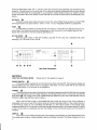
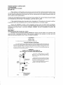
WARNING The following information is for your own safety and well being. (required by Underwriters Laboratories, Inc. UL 1270, Sec. 65) READ INSTRUCTIONS AC CORD PROTECTION All safety and operating instructions should be read before this unit is operated. The AC cord should be routed so that it is not likely to be walked on or pinched by items placed upon or against it. Please pay extra attention to cords at the plug, convenience out let and the point where they exit from the unit. RETAIN INSTRUCTIONS Retain this notice and the owners manual for future reference. HEED WARNINGS All warnings and cautions on the unit and in the owners manual should be adhered to. FOLLOW INSTRUCTIONS CLEANING The unit can be cleaned using a soft cloth dampened with a solution of liquid detergent and water. Under no circumstances should a lye solution or an abrasive cleaner such as scouring powder be used on any part of the unit. All operating and use instructions should be followed. WATER OR MOISTURE This unit should not be exposed to water or moisture. For example, near a bathtub, in a wet basement or near a swimming pool. VENTILATION This unit should be situated so that its location or position does not interfere with its proper ventilation. Be sure that at least 112" of space is provided above or below all ventilation holes. NON USE PERIOD The power cord should be unplugged from the AC outlet when the unit will not be used for an extended period of time. OBJECT OR LIQUID ENTRY Care should be taken so that objects do not fall and liquids are not spilled into the unit through ventilation holes. DAMAGE REQUIRING SERVICE The unit should be serviced by a qualified service agency when: HEAT A) This unit should be placed away from other heat producing products and adequate ventilation should be provided. B) AC ONLY This unit should be connected to an AC outlet only. With the precautions described tn the owners manual. GROUNDING Precautions should be taken for proper grounding as described in the owners manual. 1 C) D) E} The power supply cord or the plug has been damaged; or Objects have fallen, or liquid has been spilled into the unit; or The unit has been exposed to rain; or The unit does not appear to operate normally or exhibits a marked change in performance; or The unit has been dropped, or the enclosure damaged. SERVICING You should not attempt to service the unit beyond that described in the owners manual. All other servicing should be referred to a qualified service agency. ADCOM GFT-555 OWNERS MANUAL WELCOME We ask that you thoroughly read this owners manual before turning your Adcom GFT-555 tuner on. Your Adcom GFT-555 digital tuner represents excellent value in advanced tuner design. The superior performance of theGFT-555 is the result of a thorough rethinking of high performance concepts in tuner design. We have written this manual to anticipate the kinds of questions and problems that you might encounter while enjoying the full benefits of your ADCOM GFT-555 tuner. SECTION 1 WHAT TO DO WHEN YOU OPEN THE BOX Before each GFT-555 left the factory, it was carefully inspected for physical imperfections as a routine part of ADCOM's systematic quality control. This, along with full electrical and mechanical testing, should insure a product flawless in both appearance and performance. After you have unpacked the tuner; inspect it for physical damage. Save the shipping carton and all packing materials, as they are essential to reduce to a minimum the possibility of transportation damage, should the product ever need to be shipped again. In the unlikely event that damage has occurred, notify your dealer immediately and request the name of the carrier so that a written claim to cover shipping damage can be initiated. THE RIGHT TO ANY CLAIM AGAINST A PUBLIC CARRIER CAN BE FORFEITED IF THE CARRIER IS NOT NOTIFIED PROMPTLY AND IF THE SHIPPING CARTON AND PACKING MATERIALS ARE NOT AVAILABLE FOR INSPECTION. SAVE ALL PACKING MATERIALS UNTIL THE CLAIM HAS BEEN SETTLED. SECTION 2 WHERE TO PUT IT (AND WHERE NOT TO) Adequate ventilation will assure trouble free operation of your tuner. The unit may be mounted either as a free standing unit or in a standard 19" rack using the accessory rack mount adaptors, model # RM-3 (available through your ADCOM dealer). The tuner should not be totally enclosed with other heat producing components. SECTION 3 WHERE (AND HOW) ALL THE WIRES GO (Please refer to the diagram on page 3) The ultimate performance of the GFT·555, like any other fine tuner, relies on the quality and set up of the FM antenna and the quality of the broadcast signal. Please read this section carefully, the time invested will be directly returned in improved sound quality. Remember, whenever rear panel connections are being made, the GFT·555 and all associated components should be switched OFF. AM ANTENNA 0,0, and 0 The G FT·555 comes with a movable ferrite loop for AM reception O. Simply swinging this loop out away from the back panel of the GFT·555 will provide reasonable AM reception. Should you find that you are not receiving adequate AM reception, you may make your own AM antenna This is accomplished by taking one end of a single insulated wire and connecting it to the terminal on the rear panel of the GFT-555 marked AM 0. This wire may then be run to a high pOint in your home or hung out of a nearby window. Running another insulated wire from the GND (ground) terminal Oon the rear panel of the GFT·555 to a good ground may also improve AM reception. f)and 8 FM ANTENNA Your G FT-555 is provided with a folded dipole wire antenna Before the tuner is plugged in, connect this antenna to the terminals marked 300 ohms 8 on the back panel. The GFT-555 may also be used with antenna systems designed for 75 ohm co-axial (round) cable. This type of connection is common to many cable systems being used. When a 75 ohm system is being used, the cable should be terminated by an "F"-type connector. This "F" connector is then connected to the terminal labeled 75 ohms f) on the rear panel of the GFT·555. The basic folded dipole antenna included with the GFT-555 allows for the reception of FM stations 2 which are reasonably close. The "T" portion of the wire should be fully extended and oriented for best reception. The antenna will not function well if it is rolled up or casually dropped behind the tuner: Should you find that the dipole is not adequate for your reception needs, please contact your dealer to obtain further information about the variety of antennas that will provide the performance characteristics you require. OUTPUTS 0 Using the quality stereo cable provided, connect the Left and Right channel jacks on the GFT-555 to the appropriate input jacks marked "Tuner" or "Aux" on your integrated amplifier or preamplifier. FUSE fI The GFT-555 is protected by an AC line fuse. This fuse is a 1 Amp AGC type. Replace this fuse only with a fuse of the same type and rating. Replacement of this fuse with one of a higher value will not protect the tuner and will void the warranty (See Section 5). AC LINE CORD 0 With the power switch in the OFF position, plug the AC line cord into a standard wall outlet providing 110-120 volts AG, 50-60 Hz. AOCOM r.s ~Ik :. At! 3'~"""il < ,;~s- ~ U3A '02,: ',; Rear Panel Connections SECTION 4 HOW THE CONTROLS WORK POWER SWITCH (Please refer to the diagram on page 4) 0 The power switch supplies AC current to the tuner when switched ON. The frequency display will be illuminated when the power switch is activated. If this does not occur, either the AC line fuse has opened (See Section 5) or the tuner is not plugged in. TUNING «!) These 2 buttons let you select the direction of tuning by depressing either the left button for a lower frequency, or the right button for a higher frequency. The Tuning buttons work in conjunction with the FM Scan button \D. The Tuning buttons will operate differently depending upon the mode selected with the FM Scan button. (See FM Scan section below.) When the FM Scan button is illuminated (the auto mode) and either of the Tuning buttons is depressed, the tuner will scan (FM 8tations only) for the next receivable station in the chosen direction. If the FM Scan button is not illuminated, the GFT-555 is in the manual mode. In the manual mode, depressing either of the Tuning buttons will step through the frequencies in the chosen direction. If either of the Tuning buttons is depressed and held, the display will be incremented quickly until the button is released. DISPLAY m This multi-function readout displays the tuned frequency and whether you have selected AM or FM. The display also contains a signal strength meter and a Stereo indicator: The Stereo indicator will only 3 illuminate if the station being received is being broadcast in stereo and the Mute/Mono switch is disengaged (the out position). The signal strength meter on the left side of the display indicates the relative FM signal strength being received by the GFT-555. The higher the number of steps reached on the 5 step ladder of LEOs, the better the signal. You should orient your antenna so that the signal strength indicator reaches the highest level on your favorite FM stations. FMSCAN ® This button is used to select either the FM Scan mode or the Manual mode. This control is used in conjunction with the Tuning buttons~. When the FM Scan mode has been selected, an LED in the c~nterof the button will be illuminated. In the FM Scan mode, preSSing eitherof the Tuning buttons Will cause the tuner to scan in the chosen direction for the next available station. When the tuner gets to a station that is acceptable the scan function will stop. NOTE: The FM Scan function will only work for FM stations; AM Stations must be selected manually. The tuner is in the Manual mode when the FM Scan button is not illuminated. In this mode the Tuning buttons simply increment the display one step at a time in the chosen direction. When the tuner is in the manual mode, depressing and holding either of the Tuning buttons will cause the display to be incremented quickly in the chosen direction until the button is released. - ADCOM 000000000 Front Panel Controls MEMORY 6) The GFT-555 has the ability to store 8 AM and 8 FM stations in memory. To store a station in memory follow the procedure below: 1) Select either the AM or FM band. 2) Tune to the desired station. 3) Press the "enter" button. The LED in the switch button will be illuminated to show that the tuner is ready to accept a station into memory. 4) Press the desired memory location button (1 through 8). Once a station is stored, it will be maintained in memory even if the AC power is disconnected. FM/AM ~ This switch is used to select either the AM or FM band. Your selection is indicated on the Display. MUTE/MONO (L1 This switch is used to defeat the muting circuit of the GFT-555. During normal operation, the GFT-555 utilizes a muting circuit to reduce interstation noise which occurs as you tune from station to station on the FM band. The muting circuit, which is normally engaged, will not allow very weak stations to be received. Should you desire to receive a weak station, simply depress the Mute/Mono switch to defeat the muting circuit. This will allow weak stations to be received in the Mono mode, which provides the added benefit of eliminating much of the background noise common in weak stereo FM signals. HI BLEND ~ The Hi Blend switch reduces the noise received by weak FM stereo signals. FM stereo has a unique 4 property in that the majority of noise is out of phase information. This switch reduces the amount of high frequency separation between the left and right channels, and in doing so, reduces the noise without sacrificing fidelity. SECTION 5 THE CARE AND FEEDING OF YOUR GFT·555 Great care has been taken by ADCOM to assure that your tuner is as flawless in appearance as it is electronically. The front panel is heavy gauge, high-grade anodized aluminum, bead-blasted for durability and beauty. If the front panel should become fingerprinted or smeared, it can be cleaned with a damp, soft cloth. UNDER NO CIRCUMSTANCES SHOULD A STRONG OR ABRASIVE CLEANER SUCH AS SCOURING POWDER OR OVEN CLEANER BE USED ON ANY PART OF THE TUNER. FUSE 8 The tuner is protected by a line fuse on the rear panel. If the power is switched ON and the display on the front panel does not illuminate after a few seconds, shut off the tuner, unplug the AC line cord from the power outlet, and check the AC line fuse. If the fuse has opened, replace it ONLY with a fuse of equal value after carefully checking to determine the cause of the failure. If the fuse blows immediately after being replaced, a component failure must be suspected and no further attempts to replace the fuse should be made. REPLACEMENT WITH AN INCORRECT FUSE OR ONE OF A HIGHER RATING WILL NOT PROTECT THE TUNER AND WILL VOID THE WARRANTY. SECTION 6 IF YOU HAVE A PROBLEM OR QUESTION The following check list wi! assist in the correction of most problems you may encounter with your tuner. Before looking through this list check all of your connections. If the connections have been properly made, check the AC line fuse to be sure that it is not open (See Section 5 above). SYMPTOM POSSIBLE CAUSE AN 0 SOLUTION No Audio Output -AC line cord not plugged in. Poor connection between preamplifier and tuner. Make sure all plugs are pushed in all the way. FM Scan Won't Stop -Antenna not properly connected. Check your connections. FM Stereo indicator won't light -Mute/Mono switch depressed. -Station is broadcasting in Mono. -Distant station is too weak to be received in stereo. excessive Noise or Buzzing sound with program -Weak signal being received. Adjust FM antenna or install an outside FM antenna -On the AM band, fluorescent lights or electrical appliances causing interference. Try a homemade AM antenna as described in Section 3. Signal Strength Meter unstable -Antenna not oriented correctly. Try a different position for optimum signal strength. Note: This problem is occasionally accompanied by a pulsing sound. If no improvement can be made by reorienting the antenna, deactivate the muting circuit by depreSSing the Mute/Mono switch. ADCOM has a technical service department to answer all questions pertinent to the installation and operation of your unit. Please feel free to write or call us in the event of difficulty, and we shall endeavor to offer prompt advice. If your problem can not be resolved through our combined efforts, we may wish to refer you to an authorized repair agency, or we may prefer to authorize return of the unit to the factory. To aid 'US in directing you to a convenient service station, it would be helpful if you indicate which major city is accessible to your home. Please address inquiries to: 5 ADCOM TECHNICAL SERVICE DEPT.. 11 ELKINS ROAD EAST BRUNSWICK, NJ 08816 (201) 390·1130 When calling or writing about your tuner, be sure to include the model and serial number of your unit, as well as the date of purchase and the dealer from whom the unit was purchased. In the event that the unit must be returned to us for service, you will be instructed as to the proper procedure when you call or write for return authorization. UNDER NO CIRCUMSTANCES SHOUl,.D YOUR UNIT BE SHI PPED TO THE FACTORY WITHOUT PRIOR AUTHORIZATION, OR WITHOUT THE ORIGINAL CARTON AND FILLERS. If the original shipping carton has been lost or discarded, or if the carton is not in good condition, a duplicate carton may be obtained from our service department for a nominal charge. Always ship PREPAID via UPS or other recognized surface carrier. DO NOT SHIP VIA PARCEL POST, since the packing will n.ot withstand rough mail handling. We are forced to refuse most Parcel Post shipments since they arrive in such poor condition. FREIGHT COLLECT SHIPMENTS CANNOT BE ACCEPTED. SECTION 7 ADCOM PROTECTION PLAN (U.SA. ONLy) ADCOM offers the enclosed LIMITED WARRANTY. Please read the details on the warranty card carefully to fully understand the extent of the protection offered by the warranty, its limits, and what responsibilities are required of you in order to obtain its benefits. , - - ----········-----CAUTION--- POWER LINES An outdoor antenna should be located away from power lines. OUTDOOR ANTENNA GROUNDING If an outside antenna is connected to the tuner, be sure the antenna system is grounded so as to provide some protection against voltage surges and built up static charges. Section 81 0 of the National Electrical Code, ANSIINFPA No. 70-1978, provides information with respect to proper grounding of the mast and supporting structure, grounding of the lead-in wire to an antenna discharge unit, size of grounding conductors, location of antenna·discharge unit, connection to grounding electrodes, and requirements for the grounding electrode. FIGURE 65.1 EXAMPLE OF ANTENNA GROllNDING AS PE R NATIONAL ELECTRICAL CODE INSTRUCTIONS (a) Use No. 10 AWG copper or No.8 AWG aluminum or No. 17 AWG copper· clad steel or bronze wire, or larger as ground wires for both mast and lead·in. (b) Secure lead-in wire from antenna to antenna discharge unit and mast ground wire to house with stand·off insulators, spaced from 4 feet (1.22 meters) to 6 feet (1.83 meters) apart. (c) Mount antenna discharge unit as closely as possible to where lead·in enters house. MAST GROUND WIRE'" 881682 SUITABLE GROUNDING ELECTRODE DRIVEN 8 INTO THE EARTH (2.44 METERS) 6 MN10001820