1
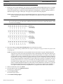
TM-2000 Trunk Master MTM-2000 Mini-Trunk Master SWP-2000 Switch Over Panel ICP-2000 Interconnect Panel User Manual TM-2000 ICP-2000 F.01U.193.264 Rev. 12 MTM-2000 SWP-2000 AUGUST/2012 ii TM-2000 & MTM-2000 User Manual PROPRIETARY NOTICE The product information and design disclosed herein were originated by and are the property of Bosch Security Systems, Inc. Bosch reserves all patent, proprietary design, manufacturing, reproduction, use and sales rights thereto, and to any article disclosed therein, except to the extent rights are expressly granted to others. COPYRIGHT NOTICE Copyright 2012 by Bosch Security Systems, Inc. All rights reserved. Reproduction, in whole or in part, without prior written permission from Bosch is prohibited. *All other trademarks are property of their respective owners. WARRANTY AND SERVICE INFORMATION For warranty and service information, refer to the appropriate web site below: THE LIGHTNING FLASH AND ARROWHEAD WITHIN THE TRIANGLE IS A WARNING SIGN ALERTING YOU OF “DANGEROUS VOLTAGE” INSIDE THE PRODUCT. CAUTION: TO REDUCE THE RISK OF ELECTRIC SHOCK, DO NOT REMOVE COVER. NO USERSERVICABLE PARTS INSIDE. REFER SERVICING TO QUALIFIED SERVICE PERSONNEL. THE EXCLAMATION POINT WITHIN THE TRIANGLE IS A WARNING SIGN ALERTING YOU OF IMPORTANT INSTRUCTIONS ACCOMPANYING THE PRODUCT. SEE MARKING ON BOTTOM/BACK OF PRODUCT. RTS ............................................... www.rtsintercoms.com/warranty WARNING: APPARATUS SHALL NOT BE EXPOSED TO DRIPPING OR SPLASHING AND NO OBJECTS FILLED WITH LIQUIDS, SUCH AS VASES, SHALL BE PLACED ON THE APPARATUS. RTSTW......................................................www.rtstw.com/warranty WARNING: THE MAIN POWER PLUG MUST REMAIN READILY OPERABLE. AudioCom................................. www.telexaudiocom.com/warranty RadioCom .................................. www.telexradiocom.com/warranty Headsets ................................ www.intercomheadsets.com/warranty CUSTOMER SUPPORT CAUTION: TO REDUCE THE RISK OF ELECTRIC SHOCK, GROUNDING OF THE CENTER PIN OF THIS PLUG MUST BE MAINTAINED. WARNING: TO REDUCE THE RISK OF FIRE OR ELECTRIC SHOCK, DO NOT EXPOSE THIS APPRATUS TO RAIN OR MOISTURE. WARNING: TO PREVENT INJURY, THIS APPARATUS MUST BE SECURELY ATTACHED TO THE FLOOR/WALL/RACK IN ACCORDANCE WITH THE INSTALLATION INSTRUCTIONS. Technical questions should be directed to: Customer Service Department Bosch Security Systems, Inc. 12000 Portland Avenue South Burnsville, MN 55337 USA Telephone: 877-863-4169 Fax: 800-323-0498 [email protected] This product is AC only. TECHNICAL QUESTIONS EMEA Bosch Security Systems Technical Support EMEA http://www.rtsintercoms.com/contact_main.php DISCLAIMER The manufacturer of the equipment described herein makes no expressed or implied warranty with respect to anything contained in this manual and shall not be held liable for any implied warranties of fitness for a particular application or for any indirect, special, or consequential damages. The information contained herein is subject to change without prior notice and shall not be construed as an expressed or implied commitment on the part of the manufacturer. Bosch Security Systems, Inc. User Manual F.01U.193.264 Rev. 12 TM-2000 & MTM-2000 User Manual iii Important Safety Instructions 1. Read these instructions. 2. Keep these instructions. 3. Heed all warnings. 4. Follow all instructions. 5. Do not use this apparatus near water. 6. Clean only with dry cloth. 7. Do not block any ventilation openings. Install in accordance with the manufacturer’s instructions. 8. Do not install near any heat sources such as radiators, heat registers, stoves, or other apparatus (including amplifiers) that produce heat. 9. Do not defeat the safety purpose of the polarized or grounding-type plug. A polarized plug has two blades with one wider than the other. A grounding type plug has two blades and a third grounding prong. The wide blade or the third prong are provided for your safety. If the provided plug does not fit into your outlet, consult an electrician for replacement of the obsolete outlet. 10. Protect the power cord from being walked on or pinched particularly at plugs, convenience receptacles, and the point where they exit from the apparatus. 11. Only use attachments/accessories specified by the manufacturer. 12. Use only with the cart, stand, tripod, bracket, or table specified by the manufacturer, or sold with the apparatus. When a cart is used, use caution when moving the cart/apparatus combination to avoid injury from tip-over. 13. Unplug this apparatus during lightning storms or when unused for long periods of time. 14. Refer all servicing to qualified service personnel. Servicing is required when the apparatus has been damaged in any way, such as power-supply cord or plug is damaged, liquid has been spilled or objects have fallen into the apparatus, the apparatus has been exposed to rain or moisture, does not operate normally, or has been dropped. Bosch Security Systems, Inc. User Manual F.01U.193.264 Rev. 12 iv Bosch Security Systems, Inc. TM-2000 & MTM-2000 User Manual User Manual F.01U.193.264 Rev. 12 Table of Contents DESCRIPTION AND SPECIFICATION ................................................................................... 3 Introduction ..............................................................................................................................................3 TM-2000/MTM-2000 ..............................................................................................................................3 Front Panel Features ............................................................................................................................................ 4 Rear Panel Features ............................................................................................................................................. 5 ICP-2000 Description ..............................................................................................................................6 ICP-2000 Reference View .......................................................................................................................6 SWP-2000 Description ............................................................................................................................7 SWP-2000 Reference View .....................................................................................................................7 Understanding Trunking ..........................................................................................................................9 Specifications .........................................................................................................................................10 TM-2000 ............................................................................................................................................................ 10 MTM-2000 ........................................................................................................................................................ 10 SWP-2000 .......................................................................................................................................................... 10 ICP-2000 ............................................................................................................................................................ 10 Environment ...................................................................................................................................................... 10 INSTALLATION ........................................................................................................................ 11 Installing Software .................................................................................................................................11 Rack Mounting .......................................................................................................................................11 Trunking Connections and Setup ...........................................................................................................12 Software Organization ...........................................................................................................................15 Hardware Requirements .........................................................................................................................15 Serial Ports ......................................................................................................................................................... 15 Ethernet Adapters .............................................................................................................................................. 15 TM-2000/MTM-2000 Software Installation Configuration Options .....................................................16 Checking IRQ Assignments ...................................................................................................................17 TM-2000 Trunk Master Software Installation .......................................................................................17 Updating the TM-2000/MTM-2000 Software .......................................................................................20 Recommended Cables ....................................................................................................................................... 26 USEFUL LINUX TRICKS ......................................................................................................... 27 Bosch Security Systems, Inc. User Manual F.01U.193.264 Rev. 12 2 Bosch Security Systems, Inc. TM-2000 & MTM-2000 User Manual User Manual F.01U.193.264 Rev. 12 CHAPTER 1 Description and Specification Introduction This manual describes the installation and operation of the TM-2000/MTM-2000 (Trunk Master and Mini-Trunk Master), SWP-2000 (Switch-Over Panel), and ICP-2000 (Interconnect Panel). TM-2000/MTM-2000 The RTS Trunking System manages intercommunications between separate intercom systems using intercom ports reserved and interconnected between the intercom systems. Keypanels or other data devices communicate with various destinations in other intercom systems via the reserved intercom ports. (This is different from bus expansion, where the bus system of two (2) or more frames are interconnected to form one (1) larger system.) The RTS Trunking System consists of an RTS Model TM-2000/MTM-2000 and one (1) or more ICP-2000s, depending on the number of intercom systems to be trunked. A backup TM-2000/MTM-2000 may also be added to prevent downtime in the event of a failure of the main master control unit. When both main and backup control units are used, an SWP-2000 is required. Bosch Security Systems, Inc. User Manual F.01U.193.264 Rev. 12 4 Description and Specification TM-2000 & MTM-2000 User Manual Front Panel Features FIGURE 1. TM-2000 front panel features. (Drawing not to scale) Bosch Security Systems, Inc. User Manual F.01U.193.264 Rev. 12 TM-2000 & MTM-2000 User Manual 1. 2. 3. 4. 5. Description and Specification 5 Status indicators for power, hard drive. Front security panel. Cooling fans (2). Front Fan Filter - slide Right to take out, slide Left to replace. Power switch (front). NOTE: Press and hold the power switch for five (5) seconds to turn off power. 6. 7. 8. System reset switch. Floppy Drive (used only for factory service). CD-ROM drive. Rear Panel Features FIGURE 2. TM-2000 rear panel features (Drawing not to scale) 1. Power supply fan 2. Power switch (rear) 3. AC power connector 4. Keyboard and Mouse connectors1 5. USB Connectors 6. Serial (COM1) port connector. See note below 7. Parallel port connectors. See note below. 8. RJ-45 Ethernet connector (not used at this time) 9. Line Out 10. Mic In 11. Line In 12. Monitor VGA 13. Serial (COM2) port connector. See note below. 14. Card slots: containing (a) RS-485 communication card(s) using MDR connector. See note below. (b) Networking connector using RJ-45 connector. See note below. NOTE: The exact location of cards and connector designations can vary from unit to unit. The diagram provided is for general feature locations only. Follow the designated labels found on your particular unit(s). 1. Used only for factory service. Bosch Security Systems, Inc. User Manual F.01U.193.264 Rev. 12 6 Description and Specification TM-2000 & MTM-2000 User Manual ICP-2000 Description The ICP-2000 is a 1RU (Rack Unit) breakout panel that converts the MDR connection provided from the TM-2000/MTM-2000 communication card(s) into 9-pin D-Sub connections. Each RS-485 communication card on the TM-2000/MTM-2000 has eight (8) ports provided on the MDR connector. The ICP-2000 breaks these eight (8) ports into individual 9-pin D-sub connections. There are two (2) MDR connectors on the ICP-2000. These two (2) connectors allow both a primary and redundant TM-2000/MTM-2000 to be connected. The connectors are wired in parallel, so it does not matter which connector the primary TM-2000/MTM-2000 and (if present) the redundant TM-2000/MTM2000 are plugged into. The ICP-2000’s connectors are labelled from left to right J1, J2, J3,....J8. These correspond from low number to high number or ports associated with the cable plugged into the ICP-2000. For example, if the cable plugged into the ICP-2000 has ports 1-8 on it, then J1 would be port 1, J2, port 2, up to J8 being port 8. If the cable plugged into an ICP-2000 has ports 9-16 on it, then J1 would be port 9, J2 port 10, up to J8 being port 16. IMPORTANT: It is important to note that in systems using VDP panels, port 1 is reserved for connection to the VDP controller and should not be connected to an ADAM or ADAM-CS. ICP-2000 Reference View ICP-2000 J1 J2 J3 J4 J5 J6 J7 J8 1 2 FIGURE 3. ICP-2000 Reference View 1. 9-pin female D-sub connector - Each connector is dedicated to an RS-485 communications port carried on the MDR cable from the TM-2000/MTM-2000. 2. MDR connectors - These are wired in parallel, so it does not matter which connector is used with a TM-2000/MTM-2000 even in redundant systems. The MDR cables are included with the TM-2000/MTM-2000 or with an add-on RS-485 port card for the TM-2000/MTM-2000. Bosch Security Systems, Inc. User Manual F.01U.193.264 Rev. 12 TM-2000 & MTM-2000 User Manual Description and Specification 7 SWP-2000 Description The SWP-2000 is a 1RU switch-over panel that provides common connections for TrunkEdit and TrunkSupervisor software packages (via serial connections to a Windows-based PC), status monitoring of both TM-2000/MTM-2000 units and control of both TM-2000/MTM-2000 units when used in a redundant configuration. SWP-2000 Reference View TM B TM A Activity Active TM Standby TM Other TM Activity Active TM Standby TM Other TM Power Go Active Go Active 1 3 2 100-240VAC 6 FIGURE 4. 7 5 4 TM B INPUT OUTPUT TRK SPVR SWP-2000 TRK EDIT 8 TRK SPVR 9 TM A INPUT TRK EDIT PP 10 11 TRK SPVR 12 TRK EDIT PP 13 14 SWP-2000 Reference View 1. Power LED - 2. TM/MTM A Status LEDs - Indicates the SWP-2000 has power. Indicates activity on the TM-2000/MTM-2000 associated with the TM/MTM A inputs. Active TM/MTM LEDs indicate activity on the TM-2000/MTM-2000 (either A or B) is active. Standby TM/MTM LEDs indicate which TM-2000/MTM-2000 (either A or B) is in standby. Other TM/MTM LEDs indicate; green, if TM/MTM B is talking; red, if not talking; and off if the system is not configured for a backup TM-2000/MTM-2000. Indications for: activity, active TM/MTM, Standby TM/MTM, other TM/MTM. 3. TM/MTM A Go Active Control Switch - Forces the TM-2000/MTM-2000 associated with the TM A inputs to become active Trunk Master. 4. TM/MTM B Status LEDs - Indicates activity on the TM-2000/MTM-2000 associated with the TM/MTM B inputs. Active TM/MTM LEDs indicate activity on the TM-2000/MTM-2000 (either A or B) is active. Standby TM/MTM LEDs indicate which TM-2000/MTM-2000 (either A or B) is in standby. Other TM/MTM LEDs indicate; green, if TM/MTM B is talking; red, if not talking; and off if the system is not configured for a backup TM-2000/MTM-2000. Indications for: activity, active TM/MTM, Standby TM/MTM, other TM/MTM. 5. TM/MTM B Go Active Control Switch - 6. AC Power - Bosch Security Systems, Inc. Forces the TM-2000/MTM-2000 associated with the TM B inputs to become active Trunk Master. User Manual F.01U.193.264 Rev. 12 8 Description and Specification TM-2000 & MTM-2000 User Manual 7. Trunk Supervisor Connector - Provides connection to the COM port of the external PC running Trunk Supervisor software. 8. TrunkEdit Connector - Provides connection to the COM port of the extra PC running TrunkEdit software. 9. Trunk Master A TrunkSupervisor Connector - Connects to COM port 2 of the TM-2000/MTM-2000 assigned to be Trunk Master A. 10. Trunk Master A TrunkEdit Connector - Connects to COM port 1 of the TM-2000/MTM-2000 assigned to be Trunk Master A. 11. Trunk Master A Parallel Port - Connects to parallel printer port of the TM-2000/MTM-2000 assigned to be Trunk Master A. Provides control from the SWP-2000 to the TM-2000/MTM-2000 and LED status monitoring of the TM-2000/MTM-2000 on the SWP-2000. 12. Trunk Master B TrunkSupervisor Connector - Connects to COM port 2 of the TM-2000/MTM-2000 assigned to be Trunk Master B. 13. Trunk Master B TrunkEdit Connector - Connects to COM port 1 of the TM-2000/MTM-2000 assigned to be Trunk Master B. 14. Trunk Master B Parallel Port - Connects to parallel printer port of the TM-2000/MTM-2000 assigned to be Trunk Master B. Provides control from the SWP-2000 to the TM-2000/MTM-2000 and LED status monitoring of the TM-2000/MTM-2000 on the SWP-2000. Bosch Security Systems, Inc. User Manual F.01U.193.264 Rev. 12 TM-2000 & MTM-2000 User Manual Description and Specification 9 Understanding Trunking In a trunking system, the audio lines (not data) of one (1) or more intercom ports are interconnected between two (2) separate intercom systems. The system administrator in each intercom system then places restrictions on these ports to prohibit them from being assigned to any keys. This reserves the ports for exclusive use as trunking lines. A special RS-485 data link is also connected from each intercom system to the Trunk Master for exchange of system control signals. The main difference between the TM-2000 and the MTM-2000 is the number of intercom systems it can communicate with. The TM-2000 supports up to 31 ports (see the note below), whereas the MTM-2000 can support up to 16 ports. Once the interconnections are completed, the Trunk Master is programmed, using TrunkEdit, to recognize the individual intercom systems. After the Trunk Master has been programmed, system administrators or keypanel users in each intercom system may request lists of people, party lines, etc. from other intercom systems for the purpose of key assignment just as they would in their own intercom system. After keys are assigned, keypanel operators can activate, talk or listen to them as they would in their own intercom system. There is no apparent difference to keypanel operators, but what occurs in the system electronics is slightly different. When a keypanel operator activates a key to talk to a destination located in another intercom system, the intercom system’s master controller does not close any cross-points, but rather, it sends this information to the Trunk Master via the data connection. The Trunk Master then checks for an available trunk line. If one (1) is available, it notifies the master controllers in the affected intercom systems to establish the communication path using the trunk line that it specifies. If no trunk lines are available, the trunking system notifies the master controller in the caller’s intercom system, which then sends a busy signal to the calling keypanel. If more than two (2) intercom systems are interconnected, additional trunk lines must be reserved and interconnected between the systems. However, it is not always necessary that two (2) intercom systems be directly interconnected as long as there is a path not more than one (1) system away to connect the two (2) systems. The trunking system can be programmed to permit cascaded trunking in which a pathway is established through an intermediate intercom system to connect two (2) endpoints. NOTE: The system and its software only support a single level of cascade. For example, System A wants to talk to System C, but it does not have a direct connection to System A and to System C. System A can talk to System C by going through (cascading) System B. However, it would be impossible for System A to talk to System D if it had to go through both System B and System C to do so, because that would require two (2) levels of cascade. Bosch Security Systems, Inc. User Manual F.01U.193.264 Rev. 12 10 Description and Specification TM-2000 & MTM-2000 User Manual Specifications TM-2000 NOTE: When powering the TM-2000 unit down, press and hold the power switch for five (5) seconds to turn power off. Height ....................................................................................................................................................................... 7” (177.8mm) Width ...................................................................................................................................................................... 19.0” (483mm) Depth ................................................................................................................................................................. 17.7” (449.58mm) Weight ...............................................................................................................................................................35.6lbs (16.15kg)2 Power................................................................................................................................................ 115/230VAC, 50/60Hz, 2.6A MTM-2000 Height ...................................................................................................................................................................... 3.47” (88 mm) Width ..................................................................................................................................................................... 16.8” (424 mm) Depth ..................................................................................................................................................................... 17.9” (457 mm) Weight ............................................................................................................................................................ 23.15 lbs (10.50 kg) Power................................................................................................................................................... 100/240VAC, 50/60Hz, 5A SWP-2000 Height ....................................................................................................................................................................... 1.75” (44mm) Width ...................................................................................................................................................................... 19.0” (483mm) Depth ........................................................................................................................................................................ 5.3” (133mm) Weight ...................................................................................................................................................................... 5.2lbs (2.4kg) Power................................................................................................................................................ 100/240VAC, 47/63Hz, 0.4A ICP-2000 Height ....................................................................................................................................................................... 1.75” (44mm) Width ...................................................................................................................................................................... 19.0” (483mm) Depth ....................................................................................................................................................................... 1.0” (25.4mm) Weight ...................................................................................................................................................................... 5.2lbs (2.4kg) Environment Operating Temperature......................................................................................................................0°C to 50°C (32°F to 122°F) Storage Temperature.......................................................................................................................-20°C to 75°C (-4°F to 167°F) Humidity................................................................................................................................................0 to 95%, non-condensing 2. The weight is based upon a unit with no PCI cards installed. Bosch Security Systems, Inc. User Manual F.01U.193.264 Rev. 12 CHAPTER 2 Installation Installing Software There are two (2) software packages that can be used with an external PC connected to the TM-2000/MTM-2000. The TrunkEdit software package is included with the TM-2000/MTM-2000 system. This package provides the user with the ability to program (configure) and monitor the TM-2000/MTM-2000. The other software package, called TrunkSupervisor, is available as a separate add-on at an additional cost. TrunkSupervisor is an advanced monitoring package for trunked systems. Both models need the following minimum system requirements: • • • • • NOTE: Windows 95 with Internet Explorer 4.01 SR2 or higher 64MB Memory 20MB Free Hard Disk space (not including swap file) TrunkEdit: One (1) serial (COM) port TrunkSupervisor: One (1) serial (COM) port, or two (2) serial (COM) ports if an AutoTIMS unit is to be monitored. A minimum of two (2) serial ports are required to run both software packages at the same time on the same computer. Three (3) serial ports are required if an AutoTIMS unit is to be monitored by TrunkSupervisor. TrunkEdit works with a PC attached to COM port 1 of the TM-2000/MTM-2000 or via the TRK EDIT port of the SWP-2000. TrunkSupervisor works with a PC attached to COM port 2 of the TM-2000/MTM-2000 or via the TRK SPVR port of the SWP-2000. See Figure 1 on page 4 for an example of how COM port 1 and 2 are labeled on the TM-2000/MTM-2000. Rack Mounting IMPORTANT: Install the TM-2000(s)/MTM-2000(s), ICP-2000(s), and SWP-2000 (if used) in the equipment rack. The units do not have special ventilation requirements. If a redundant system is being configured, it is recommended the SWP-2000 be installed between the two (2) TM-2000(s)/MTM-2000(s). Mount the ICP-2000 panel(s) either above or below the TM-2000(s)/MTM-2000(s). Bosch Security Systems, Inc. User Manual F.01U.193.264 Rev. 12 12 Installation TM-2000 & MTM-2000 User Manual Trunking Connections and Setup 1. Identify the correct wiring diagram for your system. For non-redundant TM-2000/MTM-2000 systems, use example system Figure 5 on page 21. For redundant TM-2000/MTM-2000 systems use the example in Figure 6 on page 22. Connect the trunking system components using the appropriate wiring diagram. Consult the appropriate figures as indicated in Figure 9 on page 23 and Figure 10 on page 23 for specific cable wiring diagrams. NOTE: Follow the labels as placed on the TM-2000/MTM-2000 for the specific locations of network cards and RS-485 communication cards/port numbers. The graphic below depicts how the ports are mapped to the ICP-2000 panels. CAUTION: On most systems, Port 1 can be used for trunking. On special systems that use Video Delegate Panels (VDP), port 1 is reserved for use with VDP panels. Standard systems ship from the factory without VDP support, so Port 1 is safe to use for trunking. 2. Interconnect one (1) or more intercom audio ports between the intercom systems. These ports are used for trunking communication only. Figure 7 and Figure 8 on page 23 indicate the specific cable wiring diagrams. NOTE: The number of trunk lines that you setup should be based on the number of people communicating with other intercom systems, and on the critical nature of their communication. On the other hand, there may be additional expense involved with running trunk lines when using leased lines, for example, you may want to keep the number of lines to a minimum. You may be able to get by with fewer trunk lines than the number of potential users. For example: If two (2) keypanels need to have access to another intercom system, but only one (1) of those keypanels has a critical need, you may be able to get by with one (1) trunk line. You can set the trunk priorities for the two (2) users (as described in the following paragraphs) so that the one (1) with the critical need has a higher priority. Also, keep in mind the trunking system can create a communication path by cascading through a third intercom system if that system has trunk lines to the other two (2) systems. If frequent busy signals are encountered during normal use, you may have to allocate more trunk lines. A busy signal is normally indicated by an alphanumeric key assignment and a double asterisk indication. 3. Within each intercom system, run AZedit. 4. From the Options menu, select Option|Preferences. The Preferences window appears. 5. Click the Advanced Tab. The Advanced page appears. 6. Select Enable Trunking Support. Bosch Security Systems, Inc. User Manual F.01U.193.264 Rev. 12 TM-2000 & MTM-2000 User Manual 7. Send the changes to the frame. 8. Save the file. 9. Shut down AZedit. Installation 13 NOTE: Repeat steps 3 through 9 for each intercom system that is to be trunked. 10. Restart AZedit. 11. Click the KP icon. The Keypanel/Ports window appears. 12. Select the port you want to set as a trunking port. 13. Clear all of the Scroll Enable check boxes. 14. Send your changes to the intercom system. NOTE: Also using AZedit within each intercom system, select which intercom ports, party lines, etc. will be scrollable and assignable in other intercom systems. To make intercom ports scrollable and assignable, click the KP button on the tool bar, select an intercom port, then check the Scroll Enable check boxes as desired. (Press F1 to get further help with the keypanel setup, including additional scroll enable information.) To make other types of functions (party lines, IFBs, etc.) scrollable, click the appropriate button on the AZedit tool bar as indicated, then select a specific destination and check its Scroll Enable check boxes. PL button Party Line IFB button IFBs SL button Special Lists GPI Out button General Purpose Outputs ISO button Camera ISOs 15. Send your changes to the intercom system and save the file before exiting. 16. Open TrunkEdit. 17. Configure the trunking system. 18. Click the bar labeled Intercom on the left side of the screen. 19. Click the Setup icon. A table displaying setup information for each intercom system is displayed On the initial setup, this table is empty. 20. Enter a unique four letter character name for each trunked intercom system under the Name 4 column of the setup table. You can also enter unique six (6) and eight (8) character names under the Name 6 and Name 8 columns, but these are optional. NOTE: Select the baud rate for each intercom system. The baud rate can be changed by right clicking anywhere along an intercom system’s entry in the table. A pop-up menu is displayed. Select the correct baud rate by moving the point to the Select Baud Rate entry and clicking on the correct rate. For locally trunked systems (i.e. connected via cable only), 38.4K should be selected. For remote trunked systems (i.e. connected via a leased line, fiber, etc.), 9600 should be selected. 21. Select the RS-485 COM port to be used from the TM-2000/MTM-2000 to each intercom system. NOTE: The COM port can be changed by right-clicking anywhere along an intercom system’s entry in the table. A pop-up menu is displayed. Select the correct COM port by moving the pointer to the Select COM Port entry and clicking on the desired COM port. 22. Send the changes to the TM-2000/MTM-2000 and save the file. 23. Click the bar labeled Trunk on the left side of the screen. 24. Click the Definitions icon. A table displaying trunk definitions is displayed. On initial setup this table is empty. Bosch Security Systems, Inc. User Manual F.01U.193.264 Rev. 12 14 Installation TM-2000 & MTM-2000 User Manual 25. Right click a trunk entry under the Icom 1 column. 26. Select Choose New Assignment from the pop-up menu that appears. 27. Select the intercom system is desired for this end of the trunk line. NOTE: Repeat the same for Icom 2 column in the same line except choose an intercom system different than that selected for Icom 1. This defines which two (2) intercom systems (Icom 1 or Icom 2) is trunked via this entry in the table. 28. Right-click in either the Port or Alpha entry associated with the Icom 1 entry you just made. 29. Select the Choose New Assignment from the pop-up menu that appears. 30. Select the Port or Alpha to be used for the audio trunk line from the system named in the Icom 1 column. Do the same for the Port or Alpha entry associated with the Icom 2 entry except select the Port or Alpha from the Icom 2 system for the audio trunk line. NOTE: If this particular trunk line is to be cascadable (i.e. usable to connect two (2) other adjacent systems), then be sure to set the Cascade flag. To set or clear the Cascade flag, right-click on the Cascade entry for the trunk line and select Set Cascade Flag or Clear Cascade Flag from the pop-up menu that appears. 31. Repeat this procedure for each intercom system audio trunk line needed. 32. Send the changes to the TM-2000/MTM-2000 and save the file. 33. Open AZedit. 34. Within each intercom system, assign keypanel keys as required to communicate with destinations in other intercom systems. NOTE: This is similar to assigning keys in the local intercom system, except you need to select an intercom system first when making assignments. Click the KP button on the toolbar to access keypanel setup. Select the intercom port you want to add a key assignment that communicates with a remote intercom system. If you use the Key Assignment Select screen to assign keys, proceed as for normal key assignment, except that you should select an intercom system before selecting a scroll list. 35. Send your changes to the intercom system and save the file before exiting AZedit. Bosch Security Systems, Inc. User Manual F.01U.193.264 Rev. 12 TM-2000 & MTM-2000 User Manual Installation 15 Software Organization The TM-2000/MTM-2000 consists of a PC running on Linux with real-time extensions. Once the TM-2000/MTM-2000 software is loaded on the PC, some of the kernel load modules become part of the Linux operating system. All of the TM-2000/MTM-2000 is done by running the TM-2000 software automatically starts when the computer is booted. Hardware Requirements NOTE: A keyboard and a monitor connected to an external PC connected to the TM-2000/MTM-2000 is required to perform the software installation. Serial Ports The TM-2000/MTM-2000 requires the standard COM1 and COM2 devices: COM1.............................................. Used for Trunk Edit COM2.............................................. Used for TrunkSupervisor One (1) or more serial cards must be installed in order to communicate with the intercoms. If serial cards are not installed, the TM-2000 still runs, but cannot connect to any intercoms. If a VDP (VTR Delegate Panel) controller is used, it must be connected to the first serial port on the first access card, otherwise this serial port can be used for intercom communications. The choice to enable VDP is made during the software installation. Ethernet Adapters The TM-2000 supports the use of a single Ethernet adapter. This is used for active/standby communications and for TrunkEdit communications via Ethernet. NOTE: If TrunkEdit via Ethernet is used, the computers must be connected by a switch or a hub; otherwise, a single CAT-5 crossover cable can be used between the active and standby computers. Supported Ethernet Adapters NOTE: 3COM 3c501/3/5/9, 3c529, 3c59x, and 3c9xx Intel EtherExpress Pro/100 Intel 815E chipset (e.g. Intel 82801) National Semiconductor DP8381x NetGear FA-311 AMD PCnet32 PCI There are many Ethernet Adapter cards listed as being supported by Linux; however, in order to support any other cards, the Linux kernel included with the TM-2000/MTM-2000 drivers need to be updated to support the specific Ethernet Adapter card, if it is not already supported. Bosch Security Systems, Inc. User Manual F.01U.193.264 Rev. 12 16 Installation TM-2000 & MTM-2000 User Manual TM-2000/MTM-2000 Software Installation Configuration Options NOTE: A keyboard and a monitor connected to an external PC connected to the TM-2000/MTM-2000 is required to perform the software installation. When the option to install the software is selected, the computer prompts for different pieces of information: “Is the computer to be part of an active/standby configuration?” There are three (3) choices: Stand-alone operation - This option sets the computer name to tm_solo; the IP Address to 10.201.202.203; and no standby computer. Active/standby operation (Standby by default) - This option sets the computer name to tm1; the IP Address to 10.201.202.204; and the active/standby computer to tm2/10.201.202.205. Active/standby (Standby by default) - This option sets the computer name to tm2; the IP Address to 10.201.202.205; and the active/standby computer to tm1/10.201.202.204. In addition the following parameters are set by default: Domain or Workgroup Name: WORKGROUP This is significant if you want to access the TM-2000’s hard disk from a Windows machine. Network Number: 10.0.0.0. This value may need to change if the IP Address is set to the something other than 10.x.x.x. Subnet Mask: 255.0.0.0. This value may need to change if the network number is different. Broadcast Address: 10.255.255.255. This value may need to change if the network number is different. When installing the software, it attempts to determine the hard disk drive size and partition information. You have two (2) choices: • • The user has control on how the hard disk is partitioned. The software generates the partitions. If the default partitioning is chosen, two (2) partitions are generated: one (1) at 5MB (containing essential boot files) and one (1) at 250MB. Bosch Security Systems, Inc. User Manual F.01U.193.264 Rev. 12 TM-2000 & MTM-2000 User Manual Installation 17 Checking IRQ Assignments The PCI architecture is designed to allow multiple PCI cards to share an interrupt line. The TM-2000 software allows multiple RS-485 cards to share an interrupt. However, an interrupt line which is used by an RS-485 card must not be shared with another device. It is OK the same interrupt line to be assigned to an RS-485 card and to another PCI device which doesn’t actually generate interrupts—for example, a VGA monitor. To check for IRQ conflicts, do the following: 1. Power on the TM-2000. 2. Insert software CD into the CD-ROM drive. 3. Reboot the system by pressing the reset button on the front panel or the power switch on the back panel. • If the system does not boot from the CD, enter the system BIOS setup screen. Confirm the CD-ROM drive is listed as the first boot sequence option. Linux loads and information scrolls on the computer monitor until the prompt appears. The TM-2000 Trunk Master Software prompt screen appears. TM-2000 Trunk Master Software Options: 1. Run a demo version of the TM-2000 off the CD. 2. Install the TM-2000 software on the hard drive. 3. List PCI devices and check for interrupt conflicts. Option? 4. In the Option field, enter 3. 5. Press Enter () to confirm your selection. A list of all PCI devices which use interrupts will display. NOTE: Make sure the RS-485 ACCESS I/O cards are not sharing IRQ(s) with other PCI devices. The most common conflict happens between the Ethernet card and the RS-485 cards. TM-2000 Trunk Master Software Installation There are three (3) operation modes for the TM-2000: • • • Stand-alone operation. Active/standby operation, active by default. Active/standby operation, standby by default. All three (3) modes need to be loaded and tested. NOTE: Prior to installing the Trunk Master Software on your TM-2000 check for IRQ conflicts. For more information see, “Checking IRQ Assignments” on page 17. Bosch Security Systems, Inc. User Manual F.01U.193.264 Rev. 12 18 Installation TM-2000 & MTM-2000 User Manual To install TM-2000 Trunk Master software, do the following: 1. Reboot the TM-2000 with the Trunk Master Software CD in the CD-ROM drive. The TM-2000 Trunk Master Software prompt screen appears. TM-2000 Trunk Master Software Options: 1. Run a demo version of the TM-2000 off the CD. 2. Install the TM-2000 software on the hard drive. 3. List PCI devices and check for interrupt conflicts. Option? 2. In the Option field, enter 2. 3. Press Enter () to confirm your selection. A warning message appears. You will have several chances to quit without losing any information. (More...) 4. Press Enter () to confirm your selection. The configuration window appears. Please select one of the following configurations: 1. Stand-alone operations. 2. Active/standby, active by default. 3. Active/standby, standby by default. Configuration? 5. From the Please select one of the following configurations window you can: • • • 6. select 1 if using only one (1) trunk master. select 2 if trunk master is the active unit of a redundant system. select 3 if trunk master is the standby unit of a redundant system. Press Enter () to confirm your selection. The This computer: setup information window appears. This computer: Mode: Host name: IP Address: Workgroup/Domain: Stand-alone tm_solo 10.201.202.203 WORKGROUP Do you want to change any of these values? (y/n) 7. In the Do you want to change any of these values (y/n) field, enter n (use lowercase). 8. Press Enter () to confirm your selection. The Enable VDP support (y/n) window appears. Enable VDP support? (y/n) 9. In the Enable VDP support? (y/n) field, enter n or y (use lowercase). • • Choose yes if there is a VDP-2000 in the system. Choose no for systems without VDP-2000 units. Bosch Security Systems, Inc. User Manual F.01U.193.264 Rev. 12 TM-2000 & MTM-2000 User Manual 10. Installation 19 Press Enter () to confirm your selection. If the hard drive has been previously formatted, The hard drive is already formatted, with a partition table window appears. The hard drive is already formatted, with a partition table. You have three options: 1. Abort the installation at this point. All data on the hard disk will be preserved. 2. Allow the installation to continue automatically. If you do, this DATA ON THE HARD DISK DRIVE WILL BE LOST. 3. Run the disk partition manually, and choose how you want the disk to be partitioned. Selection (1, 2, or 3)? 11. In the selection field, enter 2. 12. Press Enter () to confirm your selection. The warning *** All information on the hard drive WILL BE LOST *** window appears. *** ALL information on the hard drive WILL BE LOST *** The hard drive will be repartitioned, with the following partitions sizes: Boot partition: 5 MB Main partition: 250 MB Do you want to change these values? (y/n) 13. In the Do you want to change these values (y/n) field, enter n (use lowercase). 14. Press Enter () to confirm your selection. The Going to repartition the hard disk window appears. Going to repartition the hard disk. Okay? (yes/no) 15. In the Okay? (yes/no) field, enter yes (spell out the word yes in lowercase). IMPORTANT: If y is typed by mistake the installation of the software will be aborted. the unit will have to be rebooted to start the installation process again. 16. Press Enter () to confirm your selection. The Do you wish to choose alternate partitions window appears. Do you wish to choose alternate partitions? (y/n) 17. In the Do you wish to choose alternate partitions (y/n) field, enter n (use lowercase). 18. Press Enter () to confirm your selection. The system starts to partition/repartition the hard drive. After a few moments, the (more...) window appears. (more...) Bosch Security Systems, Inc. User Manual F.01U.193.264 Rev. 12 20 Installation 19. TM-2000 & MTM-2000 User Manual Press Enter (). The Welcome to Linux and login information window appears. (more...) ] You can press Ctrl+Alt+Del to reboot the computer. After running the BIOS self-test and initialization, the computer should prompt with “LILO”; after 5 seconds, it should automatically boot up the computer and start running the TM-2000 application. Welcome to Linux 2.4.17-rtha15. demo_tm login: 20. Press Ctrl+Alt+Delete keys at the same time to reboot the TM-2000. TIP: To prevent the unit from booting from the CD again remove the CD from the unit. When the computer monitor goes blank during the reboot press the eject button on the drive and the unit will release the CD. 21. Press Enter () to log into the unit (no password needed). NOTE: • • • tm1 login: (if the Trunk Master was setup to be the active unit by default). tm2 login: (if the Trunk Master was setup to be the standby unit by default). tm_solo login: (if the Trunk Master was setup to be a stand-alone unit). Updating the TM-2000/MTM-2000 Software IMPORTANT: In order to update the TM-2000/MTM-2000, the following files are required: update_tm.sh one or more update files, typically with a name such as to_v880.tgz These must be copied to a CD. To perform an update, do the following: 1. Log onto the TM/MTM console as the user root. A line or two of information displays followed by a prompt, similar to root@tm1~#. NOTE: A password may have been set for this user when the software was initially installed. 2. Shut down the TM-2000/MTM-2000 by running /tm/stop_tm all. Several lines of output appears followed by another prompt. 3. Insert the CD containing update_tm.sh and the first update file in the CD-ROM drive. 4. Enter the command mount /cd. 5. Enter the command sh /cd/update.sh. This copies the files to the hard drive. 6. When the update is complete, remove the CD. Update complete. you must now reboot the computer in order to restart the TM-2000 message appears. 7. Enter the command unmount /cd. 8. Remove the CD from the drive. 9. Reboot the computer. TIP: You can either use the DOS reboot sequence (Ctrl+Alt+Delete) or you can enter the command shutdown -now. Bosch Security Systems, Inc. User Manual F.01U.193.264 Rev. 12 21 Installation Bosch Security Systems, Inc. User Manual TM-2000 & MTM-2000 User Manual F.01U.193.264 Example of an non-redundant TM-2000 system. Rev. 12 FIGURE 5. 22 Installation Bosch Security Systems, Inc. User Manual TM-2000 & MTM-2000 User Manual F.01U.193.264 Example of a redundant TM-2000 system Rev. 12 FIGURE 6. TM-2000 & MTM-2000 User Manual FIGURE 7. 9-pin D-sub connector pinouts FIGURE 8. 25-pin D-sub connector pinout FIGURE 9. Installation 23 FIGURE 11. RJ-45 Connector pinout FIGURE 12. DE-9S to DE-9S audio cable FIGURE 13. DE-9S to unspecified device audio cable FIGURE 14. RJ-11 to DE-9S audio cable 50-pin MDR connector pinout FIGURE 10. RJ-11 connector pinout Bosch Security Systems, Inc. User Manual F.01U.193.264 Rev. 12 24 Installation TM-2000 & MTM-2000 User Manual FIGURE 19. ICP-2000 to unspecified device RS-485 data FIGURE 20. ADAM to unspecified device RS-485 data FIGURE 21. ADAM CS to unspecified device RS-485 FIGURE 15. RJ-11 to RJ-11 audio cable. FIGURE 16. Unspecified device to RJ-11 audio cable. cable. FIGURE 17. ICP-2000 to ADAM RS-485 data cable. data cable. FIGURE 18. ICP-2000 to ADAM CS RS-485 data cable. Bosch Security Systems, Inc. cable. FIGURE 22. TM-2000 to TM-2000 network linking (standard networking crossover) cable. User Manual F.01U.193.264 Rev. 12 TM-2000 & MTM-2000 User Manual Installation 25 TM-2000 to SWP-2000 parallel port status and control cable. FIGURE 23. FIGURE 24. Bosch Security Systems, Inc. User Manual TM-2000 to ICP-2000 RS-485 COM ports. F.01U.193.264 Rev. 12 26 Installation TM-2000 & MTM-2000 User Manual Recommended Cables • For cables using RJ-11 connections, use CAT-5 network cable. • For RJ-45 connectors, use CAT-5 network cable. RJ-45 Crossover (TM-2000 to TM-2000 network) cables can be purchased pre-made from a computer dealer. • For audio cables, use Belden 8723 or similar type with two (2) twisted pairs with shield/drain wires. • For individual RS-232 or RS-485 data cables, use Belden 8451 or similar type with single twisted pair with shield/drain wire. DO NOT EXCEED 50 FEET RUN WITH RS-232 CABLES! RS-232 cables can be purchased pre-made from a computer dealer. Use an RS-232 wired straight through for SWP-2000 to TM-2000 connections. Use a RS-232 wired “Null Modem” for PC to TM2000/SWP-2000 connection. • For TM-2000 to ICP-2000, RS-485 cables use the supplied cables. • For TM-2000 to SWP-2000 status/control cables use 25 conductor shielded cable. Do not exceed 10 feet run length with cable. FIGURE 25. PC (TrunkEdit/TrunkSupervisor) to TM-2000 or SWP-2000 RS-232 data cable. FIGURE 26. SWP-2000 Bosch Security Systems, Inc. User Manual F.01U.193.264 Rev. 12 Appendix A Useful Linux Tricks On the computer console, Shift+Page Up and Shift+Page Down can be used to scroll through the last six (6) or so pages of text. Each keystroke scrolls forward and back by half of a screen. The TM-2000/MTM-2000 is configured with two (2) virtual consoles. Normally, everything is done on the first virtual console. However, Alt+F2 can be used to switch to a second virtual console (the first time you do this, another login prompt appears); Alt+F1 can be used to switch back to the first virtual console. This can be useful if you are logged in and doing something, and need to look information up without disturbing you first session. The computer can be rebooted by typing Ctrl+Alt+D. You do not have to be logged in to do this. Alternatively, if you are logged in as root, you can type the command “shutdown - r0”. To halt the computer, rather than reboot it, type the command “shutdown -h0”, and wait for the “power down” message to appear. If you are logged in, you can log out by typing the command exit, or by pressing Ctrl+D. If the computer is restarted without shutting it down properly (i.e., there is a power failure), the computer automatically runs fsck (file system check, similar to DOS’s chkdsk). However, this normally only takes a few seconds, since there is not that much data stored on the hard disk. Bosch Security Systems, Inc. User Manual F.01U.193.264 Rev. 12 Bosch Security Systems, Inc. 12000 Portland Avenue South Burnsville, MN 55337 U.S.A. www.boschcommunications.com