1
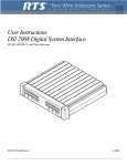
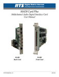
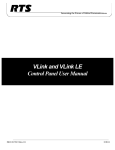
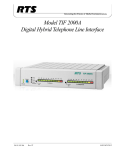
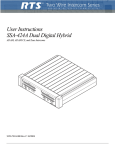
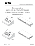
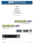
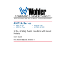
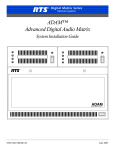
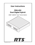
User Instructions DSI 2008 Digital System Interface ADAM, ADAM-M, ADAM CS, Zeus, and Zeus III Intercoms F.01U.193.295 Rev. 05 SEPTEMBER/2012 ii DSI-2008 PROPRIETARY NOTICE The product information and design disclosed herein were originated by and are the property of Bosch Security Systems, Inc. Bosch reserves all patent, proprietary design, manufacturing, reproduction, use and sales rights thereto, and to any article disclosed therein, except to the extent rights are expressly granted to others. COPYRIGHT NOTICE Copyright 2012 by Bosch Security Systems, Inc. All rights reserved. Reproduction, in whole or in part, without prior written permission from Bosch is prohibited. *All other trademarks are property of their respective owners. WARRANTY AND SERVICE INFORMATION For warranty and service information, refer to the appropriate web site below: RTS Intercoms ...................................... www.rtsintercoms.com/warranty RTS Digital RTSTW AudioCom RadioCom .......................................... www.telexradiocom.com/warranty Headsets ........................................ www.intercomheadsets.com/warranty THE LIGHTNING FLASH AND ARROWHEAD WITHIN THE TRIANGLE IS A WARNING SIGN ALERTING YOU OF “DANGEROUS VOLTAGE” INSIDE THE PRODUCT. CAUTION: TO REDUCE THE RISK OF ELECTRIC SHOCK, DO NOT REMOVE COVER. NO USERSERVICABLE PARTS INSIDE. REFER SERVICING TO QUALIFIED SERVICE PERSONNEL. THE EXCLAMATION POINT WITHIN THE TRIANGLE IS A WARNING SIGN ALERTING YOU OF IMPORTANT INSTRUCTIONS ACCOMPANYING THE PRODUCT. SEE MARKING ON BOTTOM/BACK OF PRODUCT. WARNING: APPARATUS SHALL NOT BE EXPOSED TO DRIPPING OR SPLASHING AND NO OBJECTS FILLED WITH LIQUIDS, SUCH AS VASES, SHALL BE PLACED ON THE APPARATUS. WARNING: THE MAIN POWER PLUG MUST REMAIN READILY OPERABLE. CAUTION: TO REDUCE THE RISK OF ELECTRIC SHOCK, GROUNDING OF THE CENTER PIN OF THIS PLUG MUST BE MAINTAINED. CUSTOMER SUPPORT WARNING: TO REDUCE THE RISK OF FIRE OR ELECTRIC SHOCK, DO NOT EXPOSE THIS APPRATUS TO RAIN OR MOISTURE. Technical questions should be directed to: Customer Service Department Bosch Security Systems, Inc. 12000 Portland Avenue South Burnsville, MN 55337 USA Telephone: 877-863-4169 Fax: 800-323-0498 [email protected] WARNING: TO PREVENT INJURY, THIS APPARATUS MUST BE SECURELY ATTACHED TO THE FLOOR/WALL/RACK IN ACCORDANCE WITH THE INSTALLATION INSTRUCTIONS. This product is AC only. TECHNICAL QUESTIONS EMEA Bosch Security Systems Technical Support EMEA http://www.rtsintercoms.com/contact_main.php DISCLAIMER The manufacturer of the equipment described herein makes no expressed or implied warranty with respect to anything contained in this manual and shall not be held liable for any implied warranties of fitness for a particular application or for any indirect, special, or consequential damages. The information contained herein is subject to change without prior notice and shall not be construed as an expressed or implied commitment on the part of the manufacturer. Bosch Security Systems, Inc. User Manual F.01U.193.295 Rev. 05 DSI-2008 iii Important Safety Instructions 1. Read these instructions. 2. Keep these instructions. 3. Heed all warnings. 4. Follow all instructions. 5. Do not use this apparatus near water. 6. Clean only with dry cloth. 7. Do not block any ventilation openings. Install in accordance with the manufacturer’s instructions. 8. Do not install near any heat sources such as radiators, heat registers, stoves, or other apparatus (including amplifiers) that produce heat. 9. Do not defeat the safety purpose of the polarized or grounding-type plug. A polarized plug has two blades with one wider than the other. A grounding type plug has two blades and a third grounding prong. The wide blade or the third prong are provided for your safety. If the provided plug does not fit into your outlet, consult an electrician for replacement of the obsolete outlet. 10. Protect the power cord from being walked on or pinched particularly at plugs, convenience receptacles, and the point where they exit from the apparatus. 11. Only use attachments/accessories specified by the manufacturer. 12. Use only with the cart, stand, tripod, bracket, or table specified by the manufacturer, or sold with the apparatus. When a cart is used, use caution when moving the cart/apparatus combination to avoid injury from tip-over. 13. Unplug this apparatus during lightning storms or when unused for long periods of time. 14. Refer all servicing to qualified service personnel. Servicing is required when the apparatus has been damaged in any way, such as power-supply cord or plug is damaged, liquid has been spilled or objects have fallen into the apparatus, the apparatus has been exposed to rain or moisture, does not operate normally, or has been dropped. Bosch Security Systems, Inc. User Manual F.01U.193.295 Rev. 05 iv Bosch Security Systems, Inc. DSI-2008 User Manual F.01U.193.295 Rev. 05 Table of Contents DESCRIPTION AND SPECIFICATIONS ................................................................................. 3 General Description .................................................................................................................................3 Features ....................................................................................................................................................3 Front and Back Panel Descriptions ..........................................................................................................4 Front Panel ........................................................................................................................................................... 4 Back Panel ........................................................................................................................................................... 4 Specifications ...........................................................................................................................................5 INSTALLATION .......................................................................................................................... 7 Mounting ..................................................................................................................................................7 4-Wire Audio Connections ......................................................................................................................7 ADAM, ADAM-M, ADAM-CS, Zeus, or Zeus III Audio Connection .............................................................. 7 Audio Connections for the Other 4-wire Communications Systems .................................................................. 8 2-Wire Audio Connections ....................................................................................................................10 RTS TW Audio Connections ............................................................................................................................. 10 Audiocom Audio Connection ............................................................................................................................ 10 Other 2-wire Audio Connection ........................................................................................................................ 11 4-Wire Call Signal Connections ............................................................................................................12 Call Signal Connection for ADAM, ADAM-M, ADAM CS, Zeus and Zeus III ............................................. 12 Call Signal Connections for other 4-wire Communications Systems ............................................................... 15 4-wire Call Send and Call Enable/Inhibit ........................................................................................................................ 15 4-wire Call Receive ......................................................................................................................................................... 16 2-Wire Call Signal .................................................................................................................................17 Call Signal Connections for Audiocom and RTS TW ...................................................................................... 17 Call Signal Connections for Other 2-Wire Communication Systems ............................................................... 17 OPERATION .............................................................................................................................. 19 Setup Instructions ...................................................................................................................................19 Operating Notes for ADAM, ADAM-M ADAM CS Zeus and Zeus III Intercom Systems .................20 ACCESS AND CONFIGURATION .......................................................................................... 21 Internal Access .......................................................................................................................................21 Mode Dip Switch Settings .....................................................................................................................22 Call Signal Option Card Installation ......................................................................................................22 Notes ......................................................................................................................................................23 Bosch Security Systems, Inc. User Manual F.01U.193.295 Rev. 05 2 Bosch Security Systems, Inc. DSI-2008 User Manual F.01U.193.295 Rev. 05 CHAPTER 1 Description and Specifications General Description The DSI 2008 Dual Digital Hybrid interfaces two (2), 2-wire intercom lines to two(2), 4-wire intercom lines. Unlike earlier analog hybrids, the DSI 2008 features advanced digital signal processing to achieve automatic nulling of the 2-wire lines. Plus, each hybrid features convenient peak-reading level meters to quickly match the levels between the lines being interfaced. The result is easy and accurate setup. With the DSI 2008, all need for test tones, nulling adjustments and ducking adjustments have been eliminated. Compatible 2-wire intercom systems include RTS TW and Audiocom. Compatible 4-wire intercom systems include ADAM, ADAM-M, ADAM CS, Zeus, and Zeus III Digital Matrix Intercom Systems. The DSI 2008 is also available with optional call signal interfacing. This option provides bi-directional call signal compatibility between the 2-wire and 4-wire intercom systems. With features like digital signal processing, peak-reading level meters and option call signal interfacing, the DSI 2008 Dual Digital Hybrid assures ease of setup and maximum transparency between intercom systems. Features Two (2) Independent Hybrids: Interface two (2) separate 2-wire lines to two (2) separate 4-wire lines. Automatic Nulling: Digital hybrids eliminate all nulling and ducking adjustments. Quick, trouble-free setup. Puts an end to concerns about echo and feedback when interfacing 2-wire lines. Peak Reading Level Meters: Quick and accurate visual audio level adjustment. No extra setup equipment or guesswork is required. Direct ADAM/ADAM-M/Zeus/Zeus III Audio Connection: Accepts standard DB-9 or RJ-11 keypanel cables. Transformer Isolated: All audio inputs and outputs are transformer isolated to prevent ground loops and hum. Call Signal Option: Detects call signals from any of the compatible 2-wire intercom systems, and then provides a +5 VDC output to the 4-wire intercom system. Accepts a contact closure input from the 4-wire system and converts it to the call signal format required by the 2-wire system. The DSI 2008 can be directly connected to an ADAM, ADAM-M, ADAM CS, Zeus, or Zeus III GPI (General Purpose Interface). GPI inputs can be programmed to activate call signals and audio paths to any of the available types of communication with the 4-wire system, including intercom ports, camera ISO circuits, IFB circuits, etc. GPI outputs can be set up to place calls only from a specific keypanel within the 4-wire system, or from any keypanel within the 4wire system that wishes to call the 2-wire system. Bosch Security Systems, Inc. User Manual F.01U.193.295 Rev. 05 4 Description and Specifications DSI-2008 Half-rack Wide, 1RU High: Two DSI 2008s fit into a single rack space. Compatible with RTS TW rack mount hardware. Can be mixed with other TW equipment. Universal Power Pack: Ready for worldwide use. Automatically accepts any main voltage from 100-250 VAC, 50/60Hz. Power pack equipped with locking DIN connector for attachment to the DSI 2008. FIGURE 1. DSI 2008 Reference View Front and Back Panel Descriptions Front Panel There is a power on/off and call indicator at the left of the front panel. This indicator lights continuously when the DSI 2008 is turned on and flashes when an incoming call signal is detected, if the call signal option board is installed. The remainder of the front panel is divided into controls and indicators for the two separate hybrids, labeled SYSTEM A and SYSTEM B. For each hybrid, there is a 10-segment, peak reading level meter to display the 4-wire output level (TO 4W). There is a recessed level set control to the left of the 4-wire meter (LEVEL SET) and there is also a recessed, 5-position range select control for the 4wire output (4W LEVEL REF SEL). Under the 4-wire meter, is an identical meter for the 2-wire output level, and there is a recessed level set control for the 2-wire output to the left of the meter. Under the 2-wire meter, there is a recessed, 5-position selector. The selector has two OFF positions for when no 2-wire input is connected. The three remaining switch positions select the 2-wire system as follows: position 1 selects RTS TW channel 1; position 2 selects RTS TW channel 2, the BAL position selects an Audiocom balanced channel. There are 3 LED indicators to display the current selection. Back Panel The power pack connector is located at the right end of the back panel. This is a locking DIN connector. The remainder of the back panel is divided into connectors for the two separate hybrids. Connectors are labeled with “J” numbers followed by “A” or “B” to indicate System A or System B. For each hybrid, there is an AUX connector. This is used to connect to/from the optional call signal card. Below the AUX connector, there are both a DB-9F connector and an RJ-11 connector for 4-wire intercom connection. These are directly compatible with standard keypanel cables. Next to the 4-wire connectors, there is a 3pin female XLR audio connector for connection to the 2-wire intercom system. Bosch Security Systems, Inc. User Manual F.01U.193.295 Rev. 05 DSI-2008 Description and Specifications 5 Specifications 2-Wire Ports Input / Output Impedance 5,000, nominal Operating Level Audiocom: 1 VRMS, nominal RTSTW: 775 mVRMS, nominal 4-Wire Ports Input Impedance 10k , nominal Output Impedance 200 Operating Levels -10dBu, 0dBu, +4dBu, +8dBu, +12dBu System to System Frequency Response 200Hz to 3.5kHz, ±4dB THD: 1% @ channel output with nominal input Environmental Operating Temp -20°C to 50°C (-4°F to 122°F) Storage Temp -40°C to 85°C (-40°F to 185°F) Humidity 0 to 95%, non-condensing Main Voltage 100 to 250 VAC, 50/60 Hz Dimensions 1.72” (44mm) High x 8.19” (208mm) Wide x 8.0” (204mm) Deep Weight 5.0lbs (2.3kg) Finish Thermoplastic front panel, aluminum case, light gray finish Approvals UL, CSA, UDE, CD Specifications subject to change without notice. Bosch Security Systems, Inc. User Manual F.01U.193.295 Rev. 05 6 Description and Specifications Bosch Security Systems, Inc. DSI-2008 User Manual F.01U.193.295 Rev. 05 CHAPTER 2 Installation Mounting Place the DSI 2008 on a desktop, or install it in an equipment rack using an RTS MCP Rack Mount Kit. Several rack mount options are available. There are no special ventilation requirements for the DSI 2008, but allow for ventilation around the power pack. • NOTE: If the DSI 2008 has the call signal option, the power indicator flashes whenever a call signal is received from either 2-wire line, and activity on the level display helps to indicate which line is calling. If the DSI 2008 is physically positioned near the 4-wire operator, this can be used as an incoming call indication for the 4-wire system, if desired (although other methods are available as described in “4-Wire Call Signal Connections” on page 12). You may wish to read about the internal mode DIP switches before mounting the DSI 2008. For further information, see Table 3 on page 22. 4-Wire Audio Connections ADAM, ADAM-M, ADAM-CS, Zeus, or Zeus III Audio Connection 1. Use standard 9-pin or RJ-11 keypanel cables. Connect from one port of your intercom system to J2A or J3A (System A connection) on the back of the DSI 2008. Connect from another port to J2B or J3B (System B connection). 2. On the DSI 2008 front panel, set the 4W LEVEL REF SEL switches to the +8dB position. Bosch Security Systems, Inc. User Manual F.01U.193.295 Rev. 05 8 Installation DSI-2008 Audio Connections for the Other 4-wire Communications Systems To connect to other 4-wire communication systems, do the following: 1. Construct 9-pin or RJ-11 cables to connect from the 4-wire system to the DSI 2008. To connect to the System A hybrid, use either J2A or J3A; for the System B hybrid, use either J2B or J3B. Pin connections are as follows: 9-Pin Connection Connector Type: 9-pin male D-subminiature Pin 1 No connection Pin 2 No connection Pin 3 No connection Pin 4 Balanced Audio + 4-wire output Pin 5 Balanced Audio - 4-wire output Pin 6 No connection Pin 7 Balanced Audio - 4-wire input Pin 8 Balanced Audio + 4-wire input Pin 9 No connection RJ-11 Connection Connector Type: RJ-11 plug Pin 1 No connection Pin 2 Balanced Audio + 4-wire input Pin 3 Balanced Audio + 4-wire output Pin 4 Balanced Audio - 4-wire output Pin 5 Balanced Audio - 4-wire input Pin 6 No Connection 2. On the DSI 2008 front panel, set the 4W LEVEL REF SEL switches to the position which most closely matches the audio input and output levels of your 4-wire system. NOTE: If you don’t know the levels, select the +8dB position for now. Bosch Security Systems, Inc. User Manual F.01U.193.295 Rev. 05 DSI-2008 Installation 9 . FIGURE 2. Rack Mount Configurations Bosch Security Systems, Inc. User Manual F.01U.193.295 Rev. 05 10 Installation DSI-2008 2-Wire Audio Connections RTS TW Audio Connections To configure 2-wire connections, do the following: 1. Use standard TW intercom cables. Standard TW system cables can carry either one (1) or two (2) channels. Each hybrid in the DSI 2008 can only interface one (1) TW channel to one (1) 4-wire channel, the channel is determined by the front panel 2W CHAN SEL switch. If your TW system cable is only carrying one (1) channel, or if you only need to connect one (1) channel, connect directly to J1A (System A) or J1B (System B). If your TW system cable is carrying two (2) channels, and you want to connect to both, use a TW-5W or similar device. NOTE: The DSI 2008 features internal DC isolation. You can therefore connect to the DSI 2008 to powered TW cables, and it will not draw any power from the TW system. 2. NOTE: On the DSI 2008 front panel: For System A and System B, set the 2W CHAN SEL switch to the appropriate position. To interface to TW channel 1 select position 1; for TW channel 2, select position 2. If the System A or System B is not used, set the 2W CHAN SEL switch to the OFF position and attach a dummy load to the TW XLR connector. Audiocom Audio Connection You can directly connect standard Audio 1-channel cables. 1. Connect one (1) Audiocom channel to the J1A connector on the back of the DSI 2008 (System A). 2. Connect a second Audiocom channel to the J1B connector (System B). If your Audiocom system uses 2-channel cables, use a JB-2 Junction Box to split the channels (Figure 3) NOTE: The DSI 2008 features internal DC isolation. You can therefore connect the DSI 2008 to powered Audiocom cables, and it will not draw any power from the Audiocom system. 3. On the DSI 2008 front panel, set the 2W CHAN SEL switches for System A or System B to the BAL position. NOTE: If System A or System B hybrid will not be used, set the 2W CHAN SEL switch to the off position and attach a dummy load to the TW XLR connector. Bosch Security Systems, Inc. User Manual F.01U.193.295 Rev. 05 DSI-2008 Installation 11 FIGURE 3. Using a JB-2 Junction Box to split a 2-channel Audiocom cable into two 1-channel cables. Other 2-wire Audio Connection 1. Use the J1A connector on the back of the DSI 2008 to connect one 2-wire line to the System A hybrid. Use the J1B connector to connect a second 2-wire line to the System B hybrid. The pin configuration for the J1A and J1B connectors depend on whether you are connecting a balanced or unbalanced 2-wire line, as follows: NOTE: TW systems must provide termination on the audio channel. Balanced Configuration Pin 1 No Connection Pin 2 Balanced Audio + Input/Output Pin 3 Balanced Audio - Input/Output ** Termination 300 There are two (2) possible configurations for unbalanced connection: Unbalanced Configuration 1 Pin 1 Audio Common Pin 2 Audio Input/Output Pin 3 No Connection ** Termination 200 Unbalanced Configuration 2 Pin 1 Audio Common Pin 2 No Connection Pin 3 Audio Input/Output ** Termination 200 2. On the DSI 2008 front panel, set the CHAN SEL switches as follows: • • • Balanced Configuration: set the CHAN SEL switches to the BAL position. Unbalanced Configuration 1: set the CHAN SEL switches to position 1. Unbalanced Configuration 2: set the CHAN SEL switches to position 2. Bosch Security Systems, Inc. User Manual F.01U.193.295 Rev. 05 12 Installation DSI-2008 NOTE: If System A or System B will not be used, set the 2W CHAN SEL switch to the off position and attach a dummy load to the TW XLR connector. 4-Wire Call Signal Connections NOTE: These connections require the call signal option. Call Signal Connection for ADAM, ADAM-M, ADAM CS, Zeus and Zeus III You can use the General Purpose Interface (GPI) connector to interface call signals. The pin-out of the connector is the same for all of these intercom systems Table 1 on page 13. ADAM/ADAM-M GPI Connector: XCP-ADAM-MC, J11 ADAM CS GPI Connector: J903 Zeus GPI Connector: J27 Zeus III GPI Connector: GPI If your intercom system is equipped with a UIO-256 (Universal Input/Output) Frame, you can also use that for connections (Table 1 on page 13 and Table 2 on page 14). As an alternative to using the GPI, you can use external components to send and receive call signals as described in “Call Signal Connections for other 4-wire Communications Systems” on page 15. Typical GPI connections are shown in Figure 4 on page 12. The example uses GPI outputs #1 and #2 and GPI Input #1. You may substitute other GPI Input and Outputs. IMPORTANT: FIGURE 4. AZedit version 1.06 or higher includes a feature which allows you to invert the action of the GPI outputs. By default, these output are set to duplicate the action of the RTS FR9528 Relay Frame accessory. This is the correct setting for use with the DSI 2008. To check the AZedit setting, select Intercom Configuration in the Options menu. Click on the Options tab, then verify that Configure onboard GPI outputs in FR9528 mode is selected. Call signal connections for ADAM, ADAM-M, ADAM CS, Zeus and Zeus III Intercom Systems. Bosch Security Systems, Inc. User Manual F.01U.193.295 Rev. 05 DSI-2008 Installation 13 This example uses GPI outputs #1 and #2 and GPI Input #1; however, you may use any other available GPI inputs and outputs. The Call Enable/Inhibit connection is optional. It gives you the ability to disable call signalling using a GPI output. Pin No. Function 1 GPI Input #1 High (5-18 VDC) 2 GPI Input #2 High (5-18 VDC) 3 GPI Input #3 High (5-18 VDC) 4 GPI Input #4 High (5-18 VDC) 5 GPI Input #5 High (5-18 VDC) 6 GPI Input #6 High (5-18 VDC) 7 GPI Input #7 High (5-18 VDC) 8 GPI Input #8 High (5-18 VDC) 9 Common* 10 Common* 11 Common* 12 Common* 13 Common* 14 GPI Out #1 15 GPI Out #2 16 GPI Out #3 17 GPI Out #4 18 GPI Out #5 19 GPI Out #6 20 GPI Out #7 21 GPI Out #8 22 Common* 23 Common* 24 Common* 25 Common* *Use any available common pin with any GPI Input or Output. TABLE 1. GPI Connector Pin-out (ADAM, ADAM-M, ADAM CS, Zeus and Zeus III) Bosch Security Systems, Inc. User Manual F.01U.193.295 Rev. 05 14 Installation TABLE 2. UIO-256 DSI-2008 GPI Input Connector (J7) GPI INPUT NUMBERSa GPI INPUT PIN NUMBERS UIO-256 Frame #1 UIO-256 Frame #2 UIO-256 Frame #3 UIO-256 Frame #4 Common Input Height (5-18 VDC) 1 17 33 49 9 34 2 18 34 50 10 35 3 19 35 51 11 36 4 20 36 52 12 37 5 21 37 53 13 38 6 22 38 54 14 39 7 23 39 55 15 40 8 24 40 56 16 41 9 25 41 57 1 26 10 26 42 58 2 27 11 27 43 59 3 28 12 28 44 60 4 29 13 29 45 61 5 30 14 30 46 62 6 31 15 31 47 63 7 32 16 32 48 64 8 33 a. Dependent on UIO-256 DIP Switch SW1 Settings for Input/Output Range as summarized in the UIO-256 Manual. Bosch Security Systems, Inc. User Manual F.01U.193.295 Rev. 05 DSI-2008 Installation 15 GPI OUTPUT NUMBERSa RELAY CONTACT PIN NUMBERS UIO-256 FRAME #1 UIO-256 FRAME #2 UIO-256 FRAME #3 UIO-256 FRAME #4 NORMAL CLOSED (NC) CONTACT COMMON CONTACT NORMAL OPEN (NO) CONTACT 1 17 33 49 38 13 40 2 18 34 50 39 14 15 3 19 35 51 41 16 43 4 20 36 52 42 17 18 5 21 37 53 44 19 46 6 22 38 51 45 20 21 7 23 39 55 41 22 49 8 24 40 56 48 23 24 9 25 41 57 26 1 28 10 26 42 58 27 2 3 11 27 43 59 29 4 31 12 28 44 60 30 5 6 13 29 45 61 32 7 34 14 30 46 62 33 8 9 15 31 47 63 35 10 37 16 32 48 64 36 11 12 a. Dependent on UIO-256 DIP Switch SW1 Settings for Input/Output Range as summarized in the UIO-256 manual. Call Signal Connections for other 4-wire Communications Systems 4-Wire Call Send and Call Enable/Inhibit The DSI 2008 accepts a switch-contact input from the 4-wire system and then generates a call signal output to the 2-wire system. The DSI 2008 also accepts an optional switch contact input to enable or inhibit call signaling between the 4-wire and 2-wire systems. Figure 5 shows the typical connections. FIGURE 5. Typical call send and call enable/inhibit connections for a 4-wire intercom system. Bosch Security Systems, Inc. User Manual F.01U.193.295 Rev. 05 16 Installation DSI-2008 4-Wire Call Receive The DSI 2008 receives call signals from the 2-wire system, then converts this to relay contact closure for use as a 4-wire call receive indication. The DSI 2008 also provides +5 VDC which can be connected to the relay contacts to generate a DC output signal instead of a contact closure. Connections for a simple contact are shown in Figure 6 on page 16. FIGURE 6. III. Call signal connections for a 4-wire intercom system other than ADAM, ADAM-M, ADAM CS Zeus and Zeus Bosch Security Systems, Inc. User Manual F.01U.193.295 Rev. 05 DSI-2008 Installation 17 2-Wire Call Signal Call Signal Connections for Audiocom and RTS TW The call signals are superimposed on the audio signal, so no separate call signal connections are required. Call Signal Connections for Other 2-Wire Communication Systems Any other 2-wire device must be able to generate and receive a 20kHz signal superimposed on the audio as follows: Balanced Audio Configuration Pin 1 No Connection Pin 2 Balanced 20 kHz + Input/Output Pin 3 Balanced 20 kHz - Input/Output DSI 2008 Signal Specifications for balanced configuration: DSI 2008 Receive: 20kHz ±100Hz, 100mVRMS DSI 2008 Send: 20kHz ±800Hz, 500mVRMS ±10% Unbalanced Configuration 1 Pin 1 20kHz Common Pin 2 20kHz Input/Output Pin 3 No Connection , Unbalanced Configuration 2 Pin 1 20kHz Common Pin 2 No Connection Pin 3 20kHz Input/Output DSI 2008 Signal Specifications for unbalanced configuration: DSI 2008 Receive: 20kHz ±100Hz, 100mVRMS DSI 2008 Send: 20kHz ±800Hz, 350mVRMS, ±10% Bosch Security Systems, Inc. User Manual F.01U.193.295 Rev. 05 18 Installation Bosch Security Systems, Inc. DSI-2008 User Manual F.01U.193.295 Rev. 05 CHAPTER 3 Operation Setup Instructions 1. Attach the power pack to the DSI 2008. 2. Apply power to all components. 3. Confirm the power indicator is lit on the DSI 2008 front panel. NOTE: The power indicator flashes when a call signal is received from a 2-wire line, if the call signal option board is attached. The DSI 2008 level displays should help to confirm which line is calling. 4. Use the level adjust trimmers to fine tune the listen levels. NOTE: For 4-wire systems other than ADAM, ADAM-M ADAM CS, Zeus and Zeus III, you may have to change the setting of the 4W LEVEL REF SEL control to establish the correct level. For 2-wire system other than Audiocom, and TW, you may have to adjust the level at the 2-wire system if you cannot establish the correct level with the 2-wire listen level trimmers. Bosch Security Systems, Inc. User Manual F.01U.193.295 Rev. 05 20 Operation DSI-2008 Operating Notes for ADAM, ADAM-M ADAM CS Zeus and Zeus III Intercom Systems 1. In AZedit use port alpha setup to name each 4-wire intercom port that is connected to the DSI 2008. Choose names which help indicate which 2-wire line is being interfaced. 2. Key assignment, party line assignment, etc. is the same as for any other intercom port. 3. Optional call signal output using the GPI: you can assign the GPI output to a talk or listen key, then activate that key to generate a call signal. Another way to generate a call signal is by assigning the GPI output as a level 2 talk key assignment for any key that is assigned to talk to the DSI 2008. However, this will cause the call lights to flash on the 2-wire line during the entire conversation. Another solution is to assign a dedicated key as a UPL resource key (which you could name CALL). Then for each key that talks to an DSI 2008 hybrid, create a UPL statement that will activate the appropriate GPI whenever the call key and the talk key are pressed. This lets you use the same call key with more than one GPI. To use, simply activate the call key and the appropriate talk key. Then, when a verbal response is received, release the call key. 4. Optional call signal input using the GPI a. In AZedit, click GPI In on the toolbar. This opens the GPI Setup screen. b. Whichever GPI Input you are using for 4-wire call receive, select that GPI Input from the list (double-click). This will open the Edit GPI Input window. c. In the Port Alpha list box, select the intercom port that is named in step 1. d. In the Key Number box, type 1. This selects key 1 at the intercom you specified in the previous step. e. Select Talk Key. f. Click Done. g. Access keypanel setup, and select the intercom port that is named in step 1. Make sure the setup page, Main is selected. h. Assign talk key number 1 to talk to the intercom port that you selected in step C. We also recommend that you assign auto-listen (AL) to the listen key above that talk key. 5. Optional call enable control. If you connected a GPI Output for use as a call enable control, you can assign that GPI output to any intercom key in the 4-wire intercom system. If System A is connected to an Audiocom or TW intercom system, pressing the key will disable the call signaling. 6. Send your changes to the intercom system. This completes any required programming for ADAM, ADAM-M, ADAM CS, Zeus or Zeus III intercom system. Bosch Security Systems, Inc. User Manual F.01U.193.295 Rev. 05 APPENDIX A Access and Configuration Internal Access 1. Remove six screws from the back cover. 2. Remove the top cover. This provides access to all internal adjustments. 3. For option card installation, slide the circuit board out toward the back to remove it from the bottom cover. AUX Telex Communications, Inc., Made in U.S.A. AUX J5 POWER +5V 3A +15V 1.6A -15V 0.3A J4A J4B RTN +5V J3B J2B 4 WIRE SYSTEM Bosch Security Systems, Inc. J1B J1A 2 WIRE SYSTEM User Manual +15V J2A J3A 4 WIRE SYSTEM -15V RTN F.01U.193.295 Rev. 05 22 DSI-2008 Mode Dip Switch Settings S301 controls the operating mode for System B and S302 controls the operating mode for System A. Settings are summarized as follows: TABLE 3. Mode DIP Switch Settings Switch Settings Description 1 2 3 4 Open Open Open Open Configuration 1, Full-Duplex Mode (Default) Closed Open Open Open Configuration 2, Half-Duplex Mode Open Open Open Closed Tone Test Mode Full-Duplex Definition: Both sides of the line can talk simultaneously. Half-Duplex Definition: Only one side of the line can talk at a time and the other side must wait until the first side is done talking before responding. 4-wire systems have priority over 2-wire system in Halfduplex mode. Tone Test Mode: Disables internal suppression of tones. Call Signal Option Card Installation To install a Call Signal Option Card in a DSI 2008 that was originally ordered without it, do the following: 1. Disassemble the DSI 2008 as previously described. 2. Assemble the standoffs to the circuit board using the supplied screws and lock-washers. 3. Connect the supplied power cable from J8 on the option card to J303 on the main board of the DSI 2008. 4. Insert the connectors on the option card into the connectors on the main board. 5. Use the remaining screws and lock-washers to secure the standoffs to the main board. 6. Reassemble the DSI 2008. Bosch Security Systems, Inc. User Manual F.01U.193.295 Rev. 05 DSI-2008 23 Notes Bosch Security Systems, Inc. User Manual F.01U.193.295 Rev. 05 Bosch Security Systems, Inc. 12000 Portland Avenue South Burnsville, MN 55337 U.S.A. www.boschcommunications.com