1
Mace Security Products, Inc. Presents:
Digital Video Recorder based on Mpeg4 Technology
Thanks for purchasing products of Mace Security International, Inc.
For your convenience in calling for service or technical support, please
record the following important information:
Model: DVR0414, DVR56MR, DVR15MR (select one)
Hard Disk: 80G, or __________
Serial #:
Date Purchased:
Sales Person:
Company Name:
Phone:
Fax:
Consult Mace’s website at http://www.mace.com for a complete line of
surveillance and security products.
2
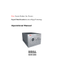
General Safety Precautions
This manual applies to Mace 4-channel non-realtime series Digital Video Recorders. There are three
models in this series, DVR0414, DVR56MR, and DVR15MR. DVR0414 will be used in all illustrations.
1.
Installation Environment
2.
Open Product Box and Verify Contents
3.
Before Power-up
3
1. Installation Environment
-
An UPS (Uninterrupted Power Supply) with power surge protection is strongly
-
Avoid extreme heat
-
Avoid direct sunlight
-
Avoid excessive humidity
-
Maintain horizontal mounting
-
Avoid excessive vibrations
-
Do not stack other devices on top of the DVR
-
Operate in well ventilated place, do not block the cooling fan
recommended for DVRs and all associated devices (routers, DSL modems, etc)
2. Open Product Box and Verify Contents
Check for the following accessories:
-
One power cord
-
One hard disc Ribbon Cable
-
One operation manual
-
One CD for utility software (normally it is not needed).
-
One remote control unit
-
Two AAA batteries
3. Before Power-up
-
Make sure the orange tab is set to 110V at the back of the DVR power supply
-
Be sure the UPS power supply is properly connected
-
Be sure to plug power cord into a reliable 110 VAC power source
4
Table of Contents
General Safety Precautions
1. Installation Environment
2. Open Product Box and Verify Contents
3. Before Power-up
Chapter 1: Product Specifications and Features
1. Product Specification
2. Product Features
3. Storage Matrix
Chapter 2: Basic System Operations
1. Start/Stop the DVR
2. Recording
3. Alarm Input/Output
4. Pan-Tilt Control
5. Network Operation
Chapter 3: Front Panel Operations
1. Front Panel Overview
2. Detail Key Function
3. Enter/Leave the Operation Menu
4. Maneuver in the Operation Menu
5. Menu Overview
6. Operation Description
6.1 Recording Control
6.2 Playback
6.3 Pan-Tilt and Zoom Camera Control
6.4 Menu Detail
5
3
4
4
4
7
8
9
11
? 13
14
15
16
16
16
17
18
19
21
22
23
27
27
27
29
30
?
?
?
?
?
?
?
?
?
?
?
?
Chapter 4: Operations over Network
1. Setting Up the Client End
2. Login and Logout
3. Operation of the Right Click Menu Items
4. Record Search and Playback
5. System Configuration
6. Assistant
Chapter 5: System Connections
1. DVR Rear View
2. RS-485 Port Connection
Appendix 1 Frequently Asked Questions
Appendix 2 Hard Disk Installation
LIMITED WARRANTY
6
37
38?
38
40
?43
45
50
55
56
57 ?
60
?62
63
?
?
?
?
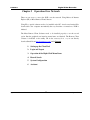
Chapter 1
Product Specifications and Features
1.
Product Specifications
Product Features
Storage Matrix
7
1. Product Specifications
Parameter
Processor
Operation
system
Video input
Video output
Audio input
Audio output
Video display
Video standard
System resource
Image resolution
Motion detection
Video compression
Audio compression
Image compression rate
Video recording speed
Image quality
Hard disk
HDD space used
Alarm input
Alarm output
Alarm relay
Network connection
Pan-tilt control
Power
Power consumption
Working temperature
Working humidity
Barometric pressure
Size
Weight
4 Channel
Real-time
!#"$%$ operation system PSOS $
('
)(
*(+(,
Channel & *(+
')0 BNC 1.0VP- P - 75 ./
BNC 1.0VP- P - 75 ./ video signal
Channel
Channel
200-1000mv10K
. (RCA)
Channel 2000mv 1K . (RCA)
1,4 ,5 windows display 0
NTSC 525 line, 60f/s PAL 625 line, 50f/s Non real-time recording and simultaneous network operation, independent local playback
Real-time monitor
2( 704 1 576, playback 352 1 288,
Area setting:
detection areas on the screen; detection sense setting: 3 levels detection sense for
each area
VBR (variable frame rate)
*(MPEG-4
)
352 1 288CIF format
Total resources 25frames for PAL mode, 30 frames for NTSC mode
6 levels selectable
One 40G hard disk preinstalled. Expandable to two large size hard disks.
Audio 3 14.4Mbyte/hour Video 3 60-460Mbyte/hour
4 channel voltage alarm input 4 5 564 15V D. C. Needed for the alarm input 3 channels output, output in open/close contact or controllable 4 12V output 30VDC 1A, 125VAC 0.5A relay output RJ45 10M/100M Ethernet connection
RS485
110+15%V 60+2% HZ
60W
7 10 8974 55 8
10 :;7 90 :
86kpa 7 106kpa
200 (breadth)x275(depth)x130mm (height)
5.5KG
8
2. Product Features
-
-
Real-time Monitor (Video Displays)
o
2 Video output ports to regular Analog Video Monitor
o
Single window (Full Screen) /4 windows (Quad) /5 windows monitor display.
Compression Method
o
Multiple video compression modes: Variable frame.
o
Single channel or 4 shared audio/video real-time recording or multi-channel non-real time
audio/video recording.
-
-
-
Storage
o
Internally can hold 2 IDE-compatible large capacity Hard disk(HDD)
o
Alternative HDD operations that will reduce the power consumption and heat emission.
o
Overwrite (FIFO) and Stop (HDD Full) modes for DVR HDD recording.
Back-up
o
USB port for external back up of records.
o
Download the files on DVR to local PC through network.
Play and Record
o
Supports multiplexed operation: live monitor, record, search for downloading, one channel
play-back and remote transmission simultaneously.
o
Multiple recording modes: Manual – Schedule – Alarm - Motion Detection. Note: Alarm
Recording and Motion Recording have Pre-Alarm function.
o
Playback: One window playback while live viewing all four channels. Playback also available
o
Fast search for reviewing manual recording and alarmed recording.
o
Multiple play-back modes: fast forward, pause, X ?, X 1/3, X1/4 S slow play and frame by
using Network Connection.
frame playback.
o
Displays Time/Date during playback.
9
-
-
-
-
Alarm relay
o
4 channel external alarm input, video lost alarm and motion detection alarm.
o
Multi channel relay switch alarm output activates alarm relay and on-site light control.
o
Circuit Protection for Alarm inputs and outputs.
Pan-tilt Control
o
Supports Camera Pan-Tilt-Zoom (PTZ) Functions using RS485 Communication Protocol.
o
Integrates multiple protocols to control various PTZ speed domes.
Communication Connection Port
o
DB 15 (15 pin) connection for alarm inputs and PTZ control.
o
RS232 port for the connection with keyboard for central control and matrix control.
o
Standard Ethernet port for remote viewing and control.
Network Operation
o
Remote real-time monitor.
o
Pan-tilt-zoom control.
o
Record search and real-time playback. Note: playback quality dependent on network conditions.
Downloading records through network.
o
System programming, settings & modification and system software upgrades available online.
o
Remote alarm processing and system log review remotely.
o
Embedded TCP/IP protocol and RTOS (Real Time Operating System) supports Web server
direct connection to operate and control all the above functions.
o
Administration mode: Three USER levels for logging in remotely.
password protected.
10
Each user login is
3. Storage Matrix
The HDD Capacities and Recording lengths are determined by capacity of the installed HDDs and the selected
image level.
The following storage time is based on the average use for HDD space for single channel recording.
Coding
CBR
Image level
Resolution
Frames
Maximum data flux
Average HDD
space < /hour =
1
352*288
30
128Kb/S
40MB
2
352*288
30
256Kb/S
80MB
3
352*288
30
384Kb/S
120MB
4
352*288
30
512Kb/S
160MB
5
352*288
30
768Kb/S
240MB
6
352*288
30
1Mb/S
320MB
Note: DVR0414 supports 30 frames per second recording in total for the whole machine. Users may chose to
record a single channel in real time (30 fps) or split the system resources evenly among several channels. Under
the LIMITED mode, every one of the four cameras will be recording at a fix rate of 7.5 fps. Under the AUTO
mode, depending on the number of channels that are recording, a channel can take 30, 15, 10 or 7.5 fps.
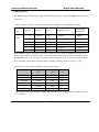
Following are storage calculation guidelines (in the number of Days):
Image
Quality
80G
MP4(CBR)
30F/S
Days
1(128kb/s)
128kb/s
61
2(256kb/s)
256kb/s
30
3(384kb/s)
384kb/s
20*
4(512kb/s)
512kb/s
15
5(768kb/s)
768kb/s
10
6(1024kb/s)
1024kb/s
8
* This reads that with an 80G harddisk, at CBR (constant bit rate) 30 fps and Image Quality 3, DVR will be able
to record 20 days.
11
80G
MP4(VBR)
Image Quality
15F/S
Days
10F/S
Days
1
85kb/s
92
71kb/s
108
69kb/s
112
2
144kb/s
56
109kb/s
72
92kb/s
84
3
158kb/s
48
133kb/s
60
114kb/s
68
4
227kb/s
36
175kb/s
44
159kb/s
48
5
292kb/s
28
258kb/s
32
200kb/s
39
6
557kb/s
16
443kb/s
18
333kb/s
24
12
7.5F/S
Days
Chapter 2 Basic System Operations
1. Start/Stop the DVR
Recording
Alarm Input/Output
Pan-tilt Control
Network
13
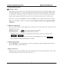
1. Start/close the recorder
>?@>
Start the recorder
Plug in the power line; switch on the power button at the back of the recorder; power indicator light on; DVR
on; default single window for the video output displays; press Enter the Log-in screen appears on Monitor; If
the starting time is within the programmed recording time, the system will start recording function automatically.
Channel indicator lights will indicate the cameras in record mode. The system will work in a normal manner.
Note: if the system stops during HDD Boot detection, the HDD may not be installed right and please check the
HDD connections (Ribbon and Power Connections). *Please unplug the 120VAC power supply during HDD
installation*
1.2 Enter the setting menu
Before you enter the menu, you must input the password. There are two levels of password—User password and
Administrator password.
Administrator password
AAAAAA (Press the Jump to Next Section key
General user password
BBBBBB ((Press the Fast Forwarder key
6 times)
6 times)
If input the user password, you have to input again at the next login; you are also not allowed to enter
system setting and admin setting.
Note: For the consideration of security, please change the Administrator password in admin settings.
Refer to Chapter 3 Front Panel Menu Operation for details.
1.3 Turning off the DVR
Press the POWER key on the front panel for 4 seconds to stop the current operations. Then switch off the power
button at the DVR rear to turn off the power.
1.4 Power off recovery
When the power is cut off abnormally, the recorder will recall it\s last state and continue where it left off. The
state indicator light is the same as it was before the power off.
14
2. Recording
The default recording mode after startup of the DVR is 24 hr continuous recording for each channel. The
User can program customized recording times for each camera. Instructions for the different recording modes are
as follows:
a) Schedule Recording:
? Enter the menu, and set the timing period for the recording. See details at Menu>System setting>Schedule
b) Manual Record Selection
? Press “Record” button on the remote controller or “Rec” on the front panel.
? Check the status of each channel in the recording menu; The Highlighted channels are in record mode.
? To select the channel to be recorded, press the related number key. Selected camera # will highlight on
your screen. When all cameras that need to be recorded are selected, press Enter to begin the recording.
? Repeat above steps and remove the highlight to stop the camera from recording.
ress Cancel or ESC to
return without changes.
c) Alarm recording
? Connect the alarm input according to the device connection and the instructions.
rogram the related settings in the menu to start Alarm recording. See details at Menu>System
setting>Alarm setting
d) Motion detection recording
? Record the channel only in need of motion detection. First confirm whether this channel is programmed in
Timing Recording; if it is, please turn off Timing Recording for the selected Camera.
? Program the related settings in the menu to start Motion detection recording.
Menu>System setting>Motion detection.
15
See details at
3. Alarm connection operation
? Connect the alarm input according to the device connection and the instructions.
? Connect the related alarm output relay on the DVR to associated alarm device. Example: lights, beeper, etc.
? Program the associated information in the menu. See details at Menu>System setting>Alarm setting
4. Pan-tilt control operation
? Confirm the proper connection of the pan-tilt-zoom and Communication Protocol. Set the Camera address.
? Confirm the proper wiring connection between the PTZ and DVR’s 15-pin port’s A & B lines.
? Set up the programming. See details at Menu>System setting>Pantilt Control
? Select full screen call-up of associated P/T/Z Camera.
? Press “Fn” on the front panel to select
? Use direction arrow keys to move and control the selections on the screen
5. Network connection operation
? Confirm correct network connections between DVR and computer
? Set the IP address, subnet mask and gateway of the computer and DVR separately. If there is no router in the
network, only the IP address is needed. If there are routers in the network, please enter the related gateway
and subnet mask.
? Ping ***.***.***.***
the IP address of the DVR to check the link of the network. A successful reply shall
look like (TTL value less than 64 ms is normal):
Reply from 68.153.205.130: bytes=32 time=31ms TTL=57
? Open IE browser and input the IP address of the DVR
? For Network operation see details at Chapter 4
16
Chapter 3 Front Panel Operations
1. Front Panel Overview
Detail Key Function
Enter/Leave the Operation Menu
Maneuver in the Operation Menu
Menu Overview
6. Operation Description
6.1 Recording
6.2 Playback
6.3 Pan-Tilt and Zoom Camera Control
6.4 Menu Detail
17
1. Front Panel Description
1.
Up Direction (Ch 1)
2.
Left Direction (Ch 3)
3.
ESC (Cancel)
4.
Down Direction (Ch 2)
5.
Enter
6.
Right Direction (Ch 4)
7.
Play Last Section (#1)
8.
Record
9.
Slow Play (#2)
10.
Function Key
11.
Play/Pause (#3)
12.
Fast Forward (#4)
13.
Play Next Section (#5)
14.
Power Switch
15.
No.1 Recording Light
16. No. 2 Recording Light
17.
No.3 Recording Light
18.
No.4 Recording Light
19.
Power Indicator
Note: Outside Ring of the jog shuttle when turning clockwise is equal to right direction arrow, turning
counterclockwise is equal to left direction arrow; inner circle turning clockwise equal to down direction,
otherwise equal to up direction.
18
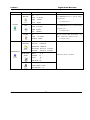
2. Keys functions
Order
14, 19
15, 18
Key name
Power switch and
indication light
Recording light
16, 17
2, 6
Logo
Function
Remark
Power switch C Power off by pressing the key for 4 seconds D
POWER
Indication light
Red
Left and right
If the light is red ,it means recording
Transverse moving, shifting level1and level2 menu; pan-tilt
control shift, when monitoring audio/video, shift channel 3 and
channel 4
1, 4
Up and down
Lengthways moving; change setup; change number; pan-tilt
control; when monitoring audio/video,, shift channel 1 and
channel 2
3
Cancel
5
Enter
ESC
ENTER
Cancel
During playback, restore to real-time monitor
Enter
Enter main menu
Press the key to display the menu of the pan-tilt moving and
Function assistant
Fn
10
camera lens control
When setting Motion Detection areas, selection on/off key
During playback, display the playback status bar
8
Manual start/stop recording, use the number key to toggle
on/off. Shadowed numbers to start recording
REC
Rec
1,2,3,4 represent the recording on/off state of the corresponding
channels. A stands for “ALL”. Press Enter to activate.
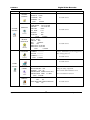
19
REC ORD
1234A
SELECT
CHANNEL
7
Play last section
Play the recording file before the current file
#1
9
Slow play
3 levels of slow play speed (?1/2 E ?1/5 E ? 1/30)
#2
Play/Pause
#3
11
Play/pause
/
When in monitor, press it to enter recording search menu
12
Fast Forward
Adjust to different Fast forward speeds
#4
13
Play next section
Play the recording file next to the current file
#5
Note: (1) The four direction keys can be used to switch channels under the single camera view.
(2) The five playback control keys represent numerical key 1 to 5 while changing the
system configuration.
20
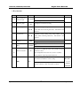
3. Operation Menu Overview
To enter the Operation Menu, press Enter key twice, the system will prompt for password.
Default Administrator password is “555555”. (Note:
Default User password is “444444”. (Note:
is the #5 key)
is the #4 key)
If not touched for 5 minutes, the system will automatically logout the currently user.
For security reason, the Administrator may choose to manually logout under Menu/ Logout
21
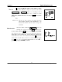
4.
Maneuver in the Menu System
Operation
Button-pressing
step
order
1 Confirm Enter
level 1
submenu
Enter level
2 submenu
Set menu
contents
Screen display
During real-time monitor, press to open the
FGIHIJ
password prompt, type in the correct password,
Enter main
menu and
Instruction
then the menu will auto open.
2 Direction arrows
Use arrows to select Icon Choice.
3 Confirm Enter
Press Enter to select choice
4 Direction
Use arrows again to select #2 submenu choice
5 Confirm Enter
Press Enter to select level 2 submenu
1 Use
Select the option to be revised, flashing item is
S T U V WXT Y[Z \ V VI] UX^
Arrow
the selection.
2 Direction
Use Up/Dn arrows to revise the settings.
S_
`
a XW T VXT S T Y/UXT U \
b c d e W c V \gf h i i
ceeW
iii
Zcj\
3 Press Enter
Save is flashing, choose to confirm whether you
Direction
KMLINPOPQIR
S c UXS \ Y
want to keep the revised setting and press Enter
again.
Direction
Exit the
current
menu
Arrow
Cancel ESC
Return to the last option of the current menu
KMLINPOPQIR
Exit to the last level menu
You can set the multiple channels before you exit the current menu and save all the settings together.
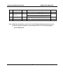
22
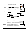
Main menu
Menu level 1
RECORD
SEARCH
LIST
ALARM
Menu level 2
CH
1
DATE
24-10-2003
TIME
2:20 PM
PLAY
START
Remarks
Use DIRECTION arrows to perform settings
in menu level 2
See details at 6.4.1
CH
1
DATE
24-10-2003
TIME
2:20 PM
LIST
SEARCH
Use DIRECTION arrows to perform setting
in menu level 2.
See details at 6.4.1
CH
1
Records associated with Alarm Inputs.
DATE
24-10-2003
able to search motion detection records.
SEARCH
START
See details at 6.4.1
HDD NUM 0 2
FILE INFO
HDD CAP
0160086 M
FREE SPACE
000000 M
FILE START 2003-04-12 01:20AM
INFORMATION
HARD DISK
STATE
FILE END
2003-05-13
INDEX
k
MASTER
SLAVE
USB STATE
VERSION
l
Information cannot be modified
W R
03:30PM
-
NO
VERSION ID 1. 11
ISSUE DATE 08-11-2003
WEB VERSION 1 23
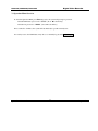
23
Not
m[n
Menu
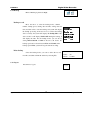
Main menu
SYSTEM
Overview
Menu level 1
GENERAL
SETTING
SCHEDULE
IMAGE
ALARM
Menu level 2
DATE
10-28-03
FORMAT MM-DD-YYYY
TIME
12:22:01
FORMAT AM/PM
SAVE
SAVETIME
HDDFULL OVERWRITE
RECORDLEN 60 MIN
REMOTEADDR 008
SAVE
CANCEL
CH
1
WEEK
SMTWTFS
TIME1
00:00 – 24:00
STATE
ON
TIME2
00:00 – 24:00
STATE
ON
SAVE
CANCEL
MODE
AUTO
FRAMERATE
AUTO
CH
1
QUANTITY
4
VIDEO LOSS
OFF NO TIP
SAVE
CANCEL
CH
1
TYPE
NORMAL CLOSE
RECORD CH
1234
ALMOUT
123
DELAY
1SEC
TIME1
00:00 – 24:00 ON
TIME2
00:00 – 24:00 OFF
SAVE
CANCEL
24
Remarks
See details at 6.4.3
See details at 6.4.3
See details at 6.4.3
See details at 6.4.3
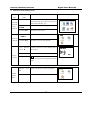
Main menu
Menu level 1
PANTILT
CONTROL
SYSTEM
NETWORK
SETTING
MOTION
DETECTION
PASSWORD
FILE DELETE
Menu level 2
CH
1
PROTOCOL NONE
BAUDRATE 4800
ADDRRESS 108
SAVE
CANCEL
Remarks
See details at 6.4.3
IP
192.168.001.108
SUBNETMASK 255.255.255.000
GATEWAY
192.168.001.001
WEB PORT
00080
TCP PORT
37777
MONITOR
TCP
PLAYBACK
TCP
SAVE
CANCEL
CH 1
DELAY 30 SEC
ALMOUT OFF
SENS
NORMAL
AREA
SET
TIME1 00:00 – 24-00 OFF
TIME2 00:00 – 24:00 OFF
SAVE
CANCEL
GUEST * * * * * *
CONFIRM * * * * * *
MANAGE * * * * * *
CONFIRM * * * * * *
SAVE
CANCEL
PASSWORD ---------
See details at 6.4.3
See details at 6.4.3
Only the Administrator password logged in is
able to change password.
See details at 6.4.4
See details at 6.4.4
ADMIN
SETTING
OTHERS
DEFAULT
ALARM TIP
OFF
SHUT PASSWORD OFF
MONITOR
OSD ON
MAINTENANCE WEEK S M T W T F S
MAINTENANCE TIME
03:10PM
SAVE
CANCEL
LOAD DEFAULT CONFIGURATION?
YES
NO
RESET NETWORK USER TO DEFAULT?
YES
NO
25
Change the setting on playback;
Turn on/off the alarm notification server;
Turn on/off shutdown restriction
See details at 6.4.4
Main menu
Menu level 1
BACKUP RECORDS
BACKUP
Menu level 2
DEVICE
USB
CH
1
If there is no backup device, the
BACKUP SPEED
NORMAL
system will indicate:
STARTING DATE
2003-3-18
STARTING TIME
12:18PM
ENDING DATE
2003-3-18
ENDING TIME
5:18PM
BACKUP
DELETE BACKUP
Remarks
ADD
DEVICE
USB
DELETE
CONFIRM
LOGOUT
26
START
NO BACKUP DVE
See details at 6.4.5
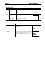
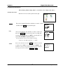
6. Menu Operation Description
6.1 Recording Operation
Model
Button-pressing order
REC
1. Record
Instruction
Display
Manually start/stop recording. Use number keys to
RECORD
toggle between On/Off (The numbers keys on the front
panel are – from 1 to 5:
op#qrs%ts
2. Related number key
,
,
/
,
1
, and
2
A
Press to toggle the recording state on/off. The
RECORD
Record.
Enter
4
SELECT CHANNEL
highlighted Camera # means Record On or selected to
3
3
1
Press Enter key to save the setting.
2
3
4
A
SELECT CHANNEL
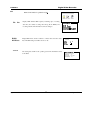
6.2 Playback operation
Button-pressing order
t/u%vxwyz
u(w
{|
}
Instruction
Display
W X\ S T W e Z \ c WXS _
S _;`
e c V \giX~ XiX~ X i iX~
VI] \gi ` i c
aYc
ZVcWV
Shortcut to the SEARCH menu. (if logged out, log back in
with password)
NOTE: If the channel is in recording mode, system will
ignore this action.
2 Play/Pause
Press twice to begin the playback (The on screen video
displays channel, date, time). If display shows no record
found, the operation will not take effect. After the
W X\ S T W e Z \ c WXS _
S _;`
e c V \giX~ XiX~ X i iX~
VI] \gi ` i
a Y c
UXTW \XS T W e
completion of the playback, display shows “Play End”.
Fn key during the playback will shift between Full Screen Mode and 5-Window Mode
27
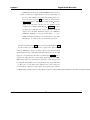
6.2.1 Playback fast play
Button-pressing order
1 Fast play
Instruction
During playback press this key to shift between 2X speed,
4X speed, or 8X speed.
28
Display
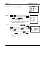
6.3 Control of Pan-Tilt and Zoom Cameras
*The PTZ Camera # must be selected on DVR before you can control the camera from
the DVR or remotely.
u}||;9|%vxwy
Button-pressing order
Instruction
1 Refer to menu operation at
In Control setting select the related Channel and Protocol,
S T U V WXT Y[Z \ V VI] UX^
see the right picture. Set the Baudrate and Address of the
S_
`
a XW T VXT S T Y e _ XS S f f i
c d e W c V \ i i
ceeW
iii
Z c j \S c UXS \ Y
6.4.4
PTZ Camera. Press Enter to save.
2 Assistant function Fn
When in real time monitoring Mode, press Fn to show the
right picture. Move
to select PAN COTROL
Or IMAGE SET .
PAN COTROL
Press Enter to show DIRECTIONS
Press Fn continuously to shift among DIRECTIONS ,
LENS CONTROL (ZOOM FOCUS IRIS) , LIGHT
CONTROL
(OFF ON). Use arrows to adjust.
d UXS VI] T UXZ
a c US T U V WXT Y
] c ^ \Z \ V
IMAGE SET
Press Enter to show VIDEO SET DEFAULT
.
DEFAULT is a factory default. SET is to be done by
user. Press
to shift between SET and DEFAULT.
When SET is selected, press Enter to do BRIGHTNESS
setting. Press
to change numbers. Press FN to
shift among BRIGHTNESS, CONTRAST, HUE, and
SATURATION. Press ESC to exit setting.
3
Direction
Control the related pan-tilt, lens and light. Use Arrows to
select.
LIGHT CONTROL
OFF ON
29
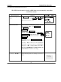
6.4 Menu Operation Detail
*The following Menu settings must be saved before the changes take effect.*
6.4.1 Record search
%(
List
The menu for record search is pictured at the right.
W \XS T W e Z \ c WXS _
First set the channel#, then date and time you want to search,
and then select START, the playback begins.
W \XS T W e Z \ c WXS _
First set the channel #, date and time you want to search, and
YI] Z V[Z \ c WXS _
then select SEARCH, the screen shows the 8 recording files
following the searching time. Use
to select the file to be
played. Press ENTER to begin the playback.
ecVg
\ 1 i i ` Xi h
VI] g
\ i h ` h c
aYc
ZVcWV
CH
e c V \g i i ` Xi h
VI] \;` i ` i c
YI] Z VZ \ c WXS _
CH 1
Note the letters before the record are equal to following
R—Record
Alarm
M—Motion Detection
A—Alarm
First set the search date, then select START, all the alarm records will
be displayed. Press
to select the record. Press ENTER to play
the alarm record. Note: motion detection alarm can not be searched in
this category, but can be searched in RECORD and LIST.
30
c Y c W [Z \ c WXS _
S _`
Z \ c WXS _gZ V c W V
DATE 2002-12-08
6.4.2
File
Z
ZV\
Menu of Information is pictured at right
Info
Display HDD number HDD capacity, remaining space, recording
I] Y \] U XT W c VI] T U
start time (the earliest recording time among all the HDDs) and
_ee
_ee
W\
I] Y
I] Y
recording end time. The information cannot be changed.
HARD
DISK State
Version
Display HDD index and the conditions of master drive and slave drive.
Note: The HDD being used will be shown as “W”.
The issuing date and ID of the operating system. The information cannot
be modified.
U d iI`
S c ai i h i i fX~
\[Z a c S \[i i i i i i
\[Z V c W V[ i i ` Xi h/i i i h i h
\ \ U e i iX~ XiI` i h¡` h ` h ` h
_ee ZVcV\
]Ue\
cZV
ZYcj
dZe
¢
\
\W
ZVcV\
`£
¤/¥
¥/¥
UXT
j \ WXZM] T U¡] U XT W c VI] T U
VERSION ID
1.00
ISSUE DATE
07-29-2003
WEB VERSION 1.23
31
6.4.3 System Setting
Z
Z V \ [Z \ V VI] UX^
Picture of the System Setting Menu
See screen shot at right:
General
^\U\WcY
DATE and TIME are used to modify the current system date and time;
after the modification reserve the change by selecting SAVETIME;
in HDDFULL if selecting OVERWRITE system covers the previous
recording files; RECORDLEN can set the length of each recording
file(15 mins, 30 mins, 60 mins)Note: 15 minutes is suggested.
Note: System time shall NOT be changed freely; otherwise it
DATE
0 6-1 1-2 0 0 3
FORMAT
MM-DD-YYYY
TIME
12:22:01AM
FORMAT
AM/PM
SAVE
SAVETIME
HDDFULL OVERWRITE
MIN
RECORDLEN
REMOTEADDR 008
SAVE
CANCEL
i
would cause the malfunction of recording search.
Schedule
Select the corresponding channel in CH. In WEEK the letter of each
day is chosen, when the letter displays are highlighted. TIME1 and
KIQIRL¦§¨L©OLPQªIO¦¬« ¯®
TIME2 express the timed recording period of the current channel. TIME2
QIR
±PLL²
³« FPL·°
KI³MN¯³IL
³« FPL´À
KI³MN¯³IL
KXNPÁL
should be after the ending time of TIME1. The setting range is
00:00-24:00 STATE ON means the time setting is on.
OFF means the
time setting is OFF.
Note: 1: If you need to record all day long, set TIME1 as 00:00-24:00
& state is on; setTIME2 as off.
2: When setting time in WEEK,
several days can be set at the same time.
When reviewing a certain channel’s timing, only the current day will
be highlighted.
32
°
K@F´³µ±´³µ¶´K
¸I¹º ¸¸»NF½¼¾¸I¹º ¸¸µ¿IF
ªI¶¶
¸I¹º ¸¸»NF½¼¾¸I¹º ¸¸µ¿IF
ªI¶¶
QMNPPQIL¨
In MODE there are two modes AUTO and LIMIT. Under the mode of
AUTO, recording rate is equally divided to each recording channel. On
the net, for those channels not recording, its monitoring picture won’t
be shown on the screen. In CH option select the related channel.
Image quality shift in 6 different level of image quality  the image
quality of the sixth level is the best. C see the attached form the
occupation space of HDD at different level D
à Video Loss is to select
the alarm ON or OFF when video is lost. Off means Alarm link
output is closed. On means Alarm link output is open. ALMOUT1,
ALMOUT2, ALMOUT 3 correspond to link output 1, 2, 3 port.
NOTIP means alarm notification is closed when alarm occurs while
TIP means it is on. Setting can be done each channel respectively.
Select the relevant Camera in CH (this recorder has 4-Ch alarm input). TYPE
has NO (normal open) NC (normal close) output modes. If the Camera
number in RECORD is selected, recording would be started for that Camera
automatically when there is alarm input. If the alarm output port is chosen, it will
trigger the corresponding relay when there is an alarm input. DELAY means to
extend the recording time after receiving alarm signal clears.10, 20, 30 ÄÄ
90SEC delays. When the outside alarm is cleared, the system will extend the
recording time automatically before closing alarm and relay output. When Time
1 or Time 2 are on, if an alarm occurs within the time of these settings, the
recording will be triggered by alarm signals. The beginning time should be
ear re
lief 3039 5059 3.99976 87.9998 re f 2439 509976 87.9998 re f 24399676700581 0 5 1.52488 0 Td (t)Tj 2.52488 0 Td (t)Tj 2.52488 0
33
IP is set by using
Network
or input the exact numbers to change
the IP address. IP address setting can only be here. The related
SUBNETMASK and GATEWAY should be set according to the IP
address. MONITOR and PLAYBACK can be changed by using
TCP/IP or MULTICAST. Save the setting in SAVE, and restart the
recorder.
LP³M±¯ªIO²´KMLP³³« P®
«¿
° ÓPÀIݬ°XйÝP¸¸¸Iݬ° Ȭ°
MK §ÌLP³MFNKM²´ÀÞÞIÝPÀÞPÞIÝPÀÞÞIÝP¸¸¸
®MN¯³ILI±NPÇß° ÓPÀIݬ°XйÝP¸¸¸IÝP¸¸°
±PLÌ©¿PªIOP³Ë¸¸¸I¹P¸
³QI¿©¿PªIOP³ËÏÕÕÕÕ
F¯ªI¬«X³ªIO˳QI¿
¿¨INPÇÌIN¯QI²à³QI¿
KXNPÁL
QMNPPQIL¨
Note:
TCP Protocol: All users are able to monitor any channel. User shall
select Camera # desired. If the transmission is over
Internet, TCP should be chosen. 2 users can log in at a
maximum.
Motion detection
Select the Camera channel in CH. ALMOUT controls the
alarming state for motion detection. SENS has three levels:
LOW, NORMAL, HIGH. AREA can be accessed by pressing ENTER.
The setting area can be divided in 192 sections. Red section means the
current cursor position, and the blue section is the motion detection area.
Areas with no color are no motion detection areas. Press Fn to locate the
current section, and then move the cursor to cover the MD area needed;
press Fn again to choose the MOTION DETECTION area. Press
get the setting and press ENTER to confirm.
34
to
F¯ª³«XªI©¦LP³ILPQ³«XªIÍKMLP³I§¿
QIR
°
³ « F« P®
ϸKMLPQ
NP¨IF¯ªI§P³
ªI¶¶
KML¯K
PªIOIFNP¨
NPOLIN
KMLP³
KM¨Pª³´°×¸I¹º ¸¸NF/¼Ø¸I¹º ¸¸@¿IF©ªI
KM¨Pª³ÀÙ¸I¹º ¸¸NFÚ¼Û¸I¹º ¸¸ ¿IFªPÜÜ
KXNPÁL
QINPPQIL¨
6.4.4 Admin setting
Password
c e I] U[Z \ V VI] UX^
Menu of Admin setting is pictured at Right:
Select GUEST and MANAGE. Press
or the number
a c Z Z ¤XT W e
key to change the password, and then confirm the change by
^ d X\ Z Vgâ â
S T U I] W [â
c U c ^ \gâ
S T U I] W [â
inputting the password again. Press ESC to go back to the sub
menu. Only MANAGE level user can change the password.
SAVE
Others
âââ
âââ
âââ
âââ
â
ââ
ââ
ââ
CANCEL
PLAYMODE has two modes, VIDEO BEST C the best flow D
and AUDIO SYNC C the best synchronization D
à When
Alarm indicator
light is on, if there is external alarm input, then alarm information comes
out á When
out. Ã If
Alarm indicator
light is off, alarm information won’t come
SHUT PASSWORD is ON, correct manage level password is
needed to be input before turning off the power of DVR. .If
PLAYMODE
ALARM TIP
AUDIO SYNC
OFF
SHUT PASSWORD OFF
MONITOR
OSD
ON
SHUT
PASSWORD is off, the DVR will be closed 4 minutes after pressing
the power button. MONITOR OSD , when it is on, real time
monitoring channel characters are displayed while it is off, no
display.
Default
Press
to get the setting and press ENTER to confirm. Press
to confirm YES or NO.
After the default setting is selected,
system will restore the original Factory Default settings. Or
restore to the original net user name and password.
File delete
e\cdYV
LOAD DEFAULT CONFIGURES?
YES
NO
RESET NETWORK USER TO
DEFAULT?
YES
NO
Used to clear the data in the HDD. Be careful with this item.
Before you delete the data, you have to input the manage password.
35
DATA DELETE
PASSWORD: _______
6.4.5 Backup
Menu of Backup is pictured at Right:
Backup records
Move the cursor to select the backup device, channel
number, backup speed, starting data and time, ending date and
time, and then select to start the backup, and system will display
the backup processing. If the user does not connect the backup
device correctly, the system will display: No backup disk; if the
device is full, it will display: Disk is full. During the backup, it
will display the time. For the backup device you can choose
ã ä Xå æ çXèéXê å ëXé ì í
ã ä åXæ çXèìXê î¬ï åMêðç í ã
åXñ
ò
ã ä åXæ çXèíXè è ê ì/ó ëXé ô äXõ
í ö äXé öï ó ÷ ì äXöXêðø ù ù ú ûXú ûò ü
í ö äXé öï ó ÷ öï ôXêðýò ü äXô
ê ó ìï ó ÷ ì äXöXêðø ù ùXú û ú ûò ü
ã ä åXæ çXè ADD í ö äXé ö
among HDD/USB/CDR. If HDD is chosen as the device, the
backup speed can be selected between Fast and Normal. If the
backup speed is Fast, system will stop the current recording.
Delete backup
Select the backup device you want to delete the records
from first, and then confirm the deletion by selecting Yes.
DELETE
DEVICE
USB
DELETE
CONFIRM
6.4.6 Logout
Press Enter to logout.
Logout
36
BACKUP
Chapter 5
Operation Over Network
There are two ways to access the DVR over the network: Using Microsoft Internet
Explorer (IE) or Mace Remote Client Software.
Using IE, no special software needs to be installed on the PC. A web control unit will be
downloaded to the computer automatically the very first time a connection to DVR is
initiated.
The Mace Remote Client Software needs to be installed properly to use the second
option. But the graphical user interface menu items are identical. The Remote Client
software is included on the utility CD in the accessory box, or you can directly
download/install from http://www.mace.com/, under Support.
1.
Setting up the Client End
2.
Login and Logout
3.
Operation of the Right Click Menu Items
4.
Record Search
5.
System Configuration
6.
Assistant
37
1. Setting up the client end
No special software is needed to install on the DVR, PC or other devices in order to access DVR using the IE
browser.
If the IE responds back “Page Cannot Be Displayed” or “Server not Found”, check your network
connection carefully.
2. Login and logout
Please input the IP address of the DVR in the address column of the browser. Take the DVR’s IP address:
192.168.0.168 as an example: Input http://192.168.0.168. Note: The first time you visit this DVR the system
will pop up the dialogue box to ask whether you accept ActiveX or not, and please choose Yes, and then the
system will install the software automatically.
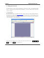
On the remote monitor display, there is a monitor video window, with selection choices:
config(system setting), Assistant(assistant setting) and so on.
38
login, logout, search,
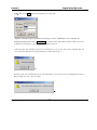
Login þ Please select login, and the following dialogue box will pop up.
Input the username and password. There are three types of Users: Administrator, User, and Guest. For
detailed information please refer to User manage ÿ
in Assistant setting. The default username is admin, & password
is admin. For Security purposes, please change the administrator password.
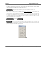
If after the input of the username and password, the following box pops up (6-3). The system is indicating that some
other user has used this name and is logged in. Please use another name to log in.
6-3
If after the input of the username and password, the following box pops up. The system is indicating that the name or
Password input is incorrect,
please try again.
39
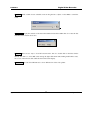
Log out: If the logged in user needs to log out, please click logout button. The popup dialogue box appears. Please
choose Yes. See 6.5.
6.5
3. Operation of the Right Click Menu Items
After you log in as Administrator, the buttons of login , video, logout, search, config & Assistant are activated. Click the
right mouse key and the following interface Display:
40
The right key menu includes: Real time monitor, Decode quality, Video windows, Playback control bar, Pan-tilt
control, Set volume, Net data flux, Full screen, Resize video and so on.
Real time monitor
Among the displayed channels, you may select the channel you want to see.
Note: When the recording mode is set to MODE (under Menu/System Setting/Image ), over the network, users
will only be able to view the channels that are scheduled (or set to be event triggered) to record at the time.
For example, if only Channel 2 and 3 are set on motion detection trigged recording at the time and the other
two channels (Channel 1 and 4) are configured recording off, remote users will not be able to view live
images from Channel 1 and 4 over the network
Playback control bar Please refer to Records playback.
Pan-tilt control
The Arrows control the moving direction of the pan-tilt and the zoom, iris & focus of the
lens. See 6.8. Press the related buttons to control. Note: Before the PTZ will operate you must set the correct
protocol of the pan-tilt on the DVR configuration menu.
41
Set volume Audio volume is User selectable. User can drag the bar to adjust or select Mute to cancel the
sound.
Net data flux Display the statistics of the network transmission data flux. When there is no network data
transmission the statistics shows zero.
Full screen There are two ways to view full screen monitor: One is to double click on the blue window
directly; the other is to select Full screen among the right click menu items. During multi-window state,
choose one of the windows and double click it for full screen display.
Resize Video User can select different ratio to show different size of the video picture.
42
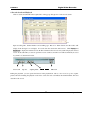
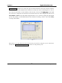
4. Records Search and Playback
Click on search, and then fill in the required info on the pop up dialogue box for the records search.
6-11
Input recording time, channel number and searching type: Record or Alarm Search, and the results will
display in the dialogue box. It displays 15 records from the search time and forward.
Click Pageup and
Pagedown to display the matched records. Double click the desired record, and system will play the selected
record. At the same time you can also perform a record download, and the record will automatically be saved
in your PC’s “C:\Download” folder.
Save record
stop save
capture picture
full screen
During the playback, you can operate the buttons in the playback bar such as: save record, stop save, capture
picture, full screen. During the playback on the video screen, the video can indicate the channel number, time and
data flux of the record.
43
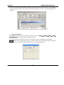
Download See 6-12, select the desired record and click Download.
6-12
The software supports the downloading of several records simultaneously. The default format of the
downloaded records’ name is:
file name, Channel #, date, time, extension name is .mp4 (Example:
a-0120021205071028.mp4, 01 means channel 1, 20021205 means December 5th of 2002, 071028 means 7
o’clock 10 minutes 28 seconds).
6-13
44
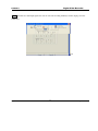
To Save a file located in the Search Record Display, Select File, press the Download button. A Save Window
opens. Input the file name and choose Save. The screen shows the processing of the downloading until the
completion.
6-14
5.
System Configuration
Click Config button and a pop up the dialogue box appears. There are General Schedule Image Alarm Motion Detection tabs of the five menu configuration screens.
Note: The grayed part of the menus that cannot be changed can only be modified directly at the DVR.
General: Include the recording length setting. In Control Column select the channel number and its PTZ
decoder’s protocol, as well as the related address for the control of the PTZ Camera.
6-15
45
Image With this menu, user can select the recording mode and the level of quality for each channel.
Style: There are two recording modes: LIMITED and AUTO. Under LIMITED mode, each channel is
allocated 7.5 frames per second. All channels will be recording at the fixed frame rate disregard the number of
channels that are actually recording.
Under AUTO mode, the total 30 frames per second are evenly distributed among the channels that are in
recording mode: 1-ch: 30 fps; 2 channels: 15 fps per channel; 3 channels: 10 fps per channel; 4 channels: 7.5
fps per channel. A channel that is set to be event-driven during the time period (alarm or motion) is
considered as in recording mode and the system will set aside resources (# of fps) in case it is triggered.
There are six levels of image quality. Level 1:data flux 128Kb/S, Level 2: 256Kb/S, Level 3: 384Kb/S, Level
4: 512Kb/S, Level 5: 768 Kb/S, Level 6: 1Mb/S.
The different data flux demands on the related bandwidth and the transmission image quality is also different.
Among them, Level 6 demands on the highest bandwidth and has the best image quality.
Net transmission Protocol- There is TCP and Multicast (two types). Multicast protocol: the 1st user logged
in has control power, can view the image at will and other users can only follow this user to view the image. 5
users are allowed to view at the same time. TCP protocol: each user can view the image at will. According to
the need, users can choose between different protocols. If viewing is through the Internet you must choose
TCP. Up-to 5 users are allowed to view at the same time.
47
Alarm When there are alarm input signals, the user can select the recording channel(s) and the output port for the
actual need.
6-20
48
Motion detection When the user sets the time period for Motion Detection, the motion detection will take
effect. The blue area is the selectable motion detection area. The User can move the dialogue box to choose
the correct area and can also set the sensitivity of the area due to the need. Click Full screen or press right
key on the area to display the motion detection area in full screen mode. After setting the area the user can
Save channel or Clear the area. The Alarm output field allows you to activate an output relay. The default
port is 2. If you want to set this channel fully as motion detection recording, you have to turn off the timing
recording of this channel.
6-21
Note: If there is an overlap between the motion detection time period and the recording time period as defined under
Schedule (under Menu/System Setting/Schedule ), continuous recording will take priority
49
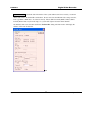
6. Assistant
Assistant
Click on Assistant setting, as following, there are User manage - Record control - Apply for
control right - Log information - System information - Channel name - Upgrade BIOS, etc.
6-22
User manage: displays the user (Log-In) information of the DVR. The buttons to the right can let an
administrator user save, add, modify, delete and cancel the information.
Three levels of user types: Administrator
fully set the system, manage the users to the system; User
can
not set system parameters or modify other users’ information. This User can select and operate existing
programming; Guest
can not set system parameter and records search, can only views the channel that the
system administrator/user is viewing.
50
Add Click Add to show the following dialogue box s
The Admin User can add user information in this dialogue box, assign the user power level. Note: There is
only one administrator allowed.
Modify Select this button to show the following. User can modify the filled-in information.
Record control Manually control the recording of each channel.
6-26
Apply for control power Web client software can supply the login of multiple users. If you want to have the
control, you can click this option and confirm to have the control. (6-27). If a new user wants to have the
51
control, the new user has to apply and gain the authorization of the existing user with control. If the logged-in
users are all normal users, the first logged-in user gains the control power automatically. If a higher lever user
logs in later, they can gain the control power automatically. If only one user logs in or the logged-in user is
the user with control, the box is gray.
The picture below (6-28) is the pop-up window when other user send request to the existing user with control.
Log information The operations on the system are all recorded in log information.
52
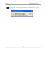
System information Check the basic information of the system. When sound is not needed, you can turn
off the audio. Due to the bandwidth considerations, the user can select the different Video transport modes,
Video type PAL or NTSC has to be selected correctly, 110vac, 60hz is normally NTSC, 220vac, 50hz is
normally PAL. If Auto recycle monitoring is on, system will sequence between all the channels
automatically with a user selectable dwell time. Net data flux: during real-time monitor will display the
statistics of the network data flux.
r
53
About Version information – This palette displays information about the DVR and may be vital when
contacting MACE Support.
54
Chapter 5
System Connections
DVR Rear View
RS-485 Port Connection
55
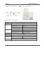
1.
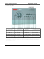
DVR Rear View
1-
Alarm – RS485 (DB-15)
2-
Fan
3-
RS232 (DB-9)
4-
Internal Modem (Not available)
5-
USB
6-
RJ45 (10 Base-T)
7-
Audio Out
8-
Audio In
9-10 Video Out (BNC)
11-14
Video In (BNC)
15- Power Switch
16- Power Socket
Network connection note: When connecting directly to the network card of a computer, please use CAT-5
Crossover Cable; when connecting to a LAN or Router use CAT-5e cable.
56
If you want to control Camera pan-tilt-zoom (P/T/Z) or activate the DVR Output relay, the 25-pin RS485
connection must be used.
See detail below.
The RS485 port connection can control various (P/T/Z) Cameras, and the specific model or protocol can be
selected from the Control Menu in System settings.
The DB25 pin outs are marked below. The definition of the pin outs are as follows: The broken line in the
graph indicates inside connection that have already been wired. !
ALARMOUT 1
NORMAL CLOSE CONTACT
ALARMOUT 1_
A LARMOUT 1
COMMON TERMINAL
NORMAL OPEN CONTACT
ALARM INPUT
@
6
1
ALARMIN4
7
12
2
@
@
8
3
RS485 B Line
B
13
ALARMIN1
14
4
10
GROUND LINE
5
0 "
t
E
E
E
21
E
s$#%%#}##|;'&(&#q)+*-,t./&
(&(q)*-,s
Decoder
Alarm output3 common terminal
Alarm output3common open contact
+12V
á
A
15
w
"
B
A
Decoder
9
ALARM INPUT
120 A/BDCDEGFHEJIHKJLDMJC
RS485 A Line
11
output
Alarm output 2
Alarm output2
ALARMOUT3_C
ALARMOUT3_NO
common terminal
common open contact
ALARMOUT3_C
ALARMOUT3_NO
&
(&(q)
345t6,(
7#wv98vx#|};: <== &
(&(q)
345,#7(w%v>3#}%?: < txr &
(&(q)
345 ,(
7#w%v>3
}%
57
#"
ts < t N$O t p
"
tt
1
u#P} < 8w%
qUs &ÊvV%#} <
wv
|#Q%x(}¡(P}SR
t W1
qUs NX
wvxw
7É|
}%|
|;: <
t NT #{%(#|
vY%};:
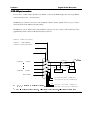
- Connection of the alarm input:
Pwr Supply, Alarm Device and DVR connection
Alarm Device
+12V
]
GND
]
Com
]
NC
]
[
ALARMIN
\
[
O t p
Typical
connection to
DVR alarm in.
GND
T ,o
uP($U
{vy
Z Instruction of the alarm input end:
8 channel alarm inputs with NO or NC alarm (normally open or normally close type). The power out of the
alarm sensor can be provided by the DVR (Low current only) or (External alarm power supply)
nstructions for alarm device power from DVR:
N/O or NC alarm outputs refer to information below.
nstruction of the controllable +12V
Available for Low Current Power to Alarm devices.
58
nstruction of RS485 A & B line:
Used to connect the A and B line of the PTZ units.
59
odule sketch of the alarm input end
odule sketch of the alarm output end
Z Relays’ parameter of the alarm output end
Model: G6H
Relay Material
Silver
Rating, resistance &
Rated switch capacity
30VDC 1A, 125VAC 0.5A
load.
Maximum switch power
62.5VA 33W
Maximum switch voltage
125VAC, 110VDC
Maximum switch Current
1A
Pins with same polarity
750VAC 1minute 50/60Hz
pins with different polarity
1000VAC 1minute 50/60Hz
between relay and loop
1000VAC 1minute 50/60Hz
between relays with same polarity
1500V (10 ^ 160us)
Insulation
Surge voltage
Length of open time
3ms max
Length of close time
3ms max
Longevity
Temperature
Mechanical
100 ^ 106 (10Hz)
Electric
200 ^ 103 (0.5Hz)
-40~+70 _
60
Appendix 1
1.
Frequently Asked Questions
After Power up, “No HDD” message is flashing on the local monitor
This is an indication that either the harddisks are not installed correctly or no harddisk is installed at all. Refer to
Appendix 2 Hard disk installation. Also inside the DVR there is a yellow sticker with instructions on harddisk
installation.
2.
When I power down the DVR, why do I have to press and hold the power button for 4 seconds?
First of all, using the front orange power button to shut down the DVR will make sure the DVR properly finish and
close all it operation and file system, thus eliminate many possible causes for harddisk errors leading to data loss.
This is the correct way of powering down a DVR.
Secondly, requiring holding the button for over 4 seconds is to avoid accidental shutdown of the DVR due to
unintended touch of the button. You can make the shutdown more secure (i.e. avoid unauthorized shutting down)
by
activating
the
shutdown
password
protection
feature.
(MENU->ADMIN
SETTING->OTHERS->SHUTDOWN PASSWORD)
3.
What does the sound of the buzzer mean when normally starting the machine
When the machine is started successfully, it will tone out a short ring.
When the HD can not be identified, it would tone out a longer ring.
When communication with the controller panel is abnormal, it sends out a tone of one long ring and two short in
series.
4.
Can I control the recording time?
The recording time unit is per day. Besides timing recording, there are other recording methods such as motion
detection recording, manual recording, external event triggering recording. Confirm that each of the settings is
correct.
5.
The indicator light is flashing while recording `
Check the external video input signal first. Such phenomena would happen when the input signal is not
standard. If it is not the input signal, it must be caused by that the reading speed of the HD is too slow. In this
61
situation, the current HD should be changed.
6.
Why the screen is black after I switch off and on the power?
The power supply comes with the DVR has a built-in protection mechanism. After the power is shut down, you
have to wait for at least 5 seconds before turn it on again. Turn off the power, wait for 5 seconds, and turn it on
again. If this does not correct the problem, contact your Mace technical support hotline.
7.
What kind of external equipment could be connected to the Recorder?
It can work together with various matrix units, multiplexers, switchers, quads and PTZ Domes.
62
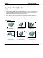
Appendix 2
Hard Disk Installation
Hard disk installation
There is one 40G hard disk (HD) preinstalled in the Mace DVR, unless you ordered a special configuration. So
normally you DO NOT have to go through these steps. This procedure only applies to cases where there is no
built-in hard disk in the DVR or additional hard disks need to be installed.
In total, a maximum of 4 large capacity hard disks can be installed inside the machine if a CD burner is not
needed. With a CD burner, there can be a total of 5 internal large capacity hard disks. User can decide the
number of hard disks according to required image quality, recording time and recording length.
Installation steps
a
Dismantle the fixed
b
Dismantle the HD Bracket
e
Install the first HD
c
screw of the top cover
Install the second HD
d
Put back the HD Bracket
63
f
Put back the Cover Case
LIMITED WARRANTY
Mace Security Products, Inc. (MACE) warrants to the original purchaser of this product that it shall be free of defects
resulting from workmanship or components fro a period of one (1) year from the date of sale. Defects covered by this
Limited Warranty shall be corrected wither by repair or, at MACE’s discretion by replacement. In the event of
replacement, the replacement unit will be warranted for the remainder of the original one (1) year period or thirty (30)
days, whichever is longer. THERE ARE NO OTHER ORAL OR WRITTEN WARRANTIES, EXPRESSED OR
IMPLIED, INCLUDING BUT NOT LIMITED TOTHOSE OF MERCHANTABILITY OR FINESS FOR A
PURTICULAR PURPOSE.
This Limited Warranty is nontransferable and does not apply if the product has been damaged by negligence, accident,
abuse, misuse, modification, or misapplication. To be eligible for warranty service, a defective product must be sent to
and received by MACE within twelve (12) months of the date of sale and be accompanied with proof of purchase. MACE
does not warrant that this product will meet your requirements; it is your sole responsibility to determine the suitability of
this product for your purposes. MACE does not warrant the compatibility of this product with your computer or related
peripherals software.
MACE’S SOLE OBLIGATION AND LIABILITY UNDER THIS WARRANTY IS LIMITED TO THE REPAIR OR
REPLACEMENT OF A DEFECTIVE PRODUCT. THE MANUFACTURER SHALL NOT, IN ANY EVENT, BE
LIABLE TO THE PURCHASER OR ANY THIRD PARTY FOR ANY INCIDENTAL OR CONSEQUENTIAL
DAMAGES OR LIABILITY IN TORT RELATING TO THIS PRODUCT OR RESULTING FORM ITS USE OR
POSSESSION.
64