1
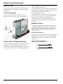
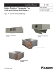
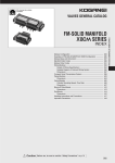
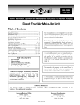
ThinLine™ 3G Vertical Unit Heaters Catalog 723-1 Type FHVC, FHVH, FHVS, FHWC Vertical Design Model FHVC Model FHVS Engineered for flexibility and performance™ Nomenclature and Certification . . . . . . . . . . . . . . . . 3 Unit Selection . . . . . . . . . . . . . . . . . . . . . . . . . . . . . . . 13 ThinLine™ 3G Vertical Unit Heaters . . . . . . . . . . . . 3 Unit Selection . . . . . . . . . . . . . . . . . . . . . . . . . . . . . 13 AHRI Certification . . . . . . . . . . . . . . . . . . . . . . . . . 3 Basic design data . . . . . . . . . . . . . . . . . . . . . . . . . . 13 Agency Listed . . . . . . . . . . . . . . . . . . . . . . . . . . . . 3 Unit Size . . . . . . . . . . . . . . . . . . . . . . . . . . . . . . . 13 Features and Benefits . . . . . . . . . . . . . . . . . . . . . . . . 4 Performance Data . . . . . . . . . . . . . . . . . . . . . . . . . . . 14 The ThinLine™ 3G Advantage . . . . . . . . . . . . . . . . . 4 Heating Performance - Hot Water Coil . . . . . . . . . . 14 Air Volume Capacity Data . . . . . . . . . . . . . . . . . . . . 15 Electrical Data . . . . . . . . . . . . . . . . . . . . . . . . . . . . . . 16 Motor Electrical Data . . . . . . . . . . . . . . . . . . . . . . . . 17 Physical Data . . . . . . . . . . . . . . . . . . . . . . . . . . . . . . . 18 For building owners . . . . . . . . . . . . . . . . . . . . . . . 4 For specifying engineers . . . . . . . . . . . . . . . . . . . 4 For contractors . . . . . . . . . . . . . . . . . . . . . . . . . . . 4 Options and Accessories . . . . . . . . . . . . . . . . . . . . . . 6 Control Options . . . . . . . . . . . . . . . . . . . . . . . . . . . . 6 Manual 4-Position Fan Switch . . . . . . . . . . . . . . . 6 Unit-Mounted, Mechanical (Analog) Thermostat With 4-Position Fan Switch . . . . . . . . 6 Digital Thermostats . . . . . . . . . . . . . . . . . . . . . . . 6 Low Voltage Interface Board . . . . . . . . . . . . . . . . 8 Customer-Supplied Controls . . . . . . . . . . . . . . . . 8 Decorative Wall Plate Option . . . . . . . . . . . . . . . . 8 Cabinet Color Options . . . . . . . . . . . . . . . . . . . . . 8 Fresh Air Damper Options (Manual and Motorized) . . . . . . . . . . . . . . . . . . . . 8 Unit Data . . . . . . . . . . . . . . . . . . . . . . . . . . . . . . . . . 18 Unit Dimensions . . . . . . . . . . . . . . . . . . . . . . . . . . . 19 Decorative Wall Plate Dimensions . . . . . . . . . . . . . 23 Fresh Air Intake Box Dimensions . . . . . . . . . . . . . . 23 Engineering Guide Specification . . . . . . . . . . . . . . . 24 McQuay ThinLine 3G™ Unit Heater . . . . . . . . . . . . 24 Performance . . . . . . . . . . . . . . . . . . . . . . . . . . . . 24 General Construction - All Units . . . . . . . . . . . . . 24 Cabinet . . . . . . . . . . . . . . . . . . . . . . . . . . . . . . . . 24 Coils . . . . . . . . . . . . . . . . . . . . . . . . . . . . . . . . . . 24 Supply Fan . . . . . . . . . . . . . . . . . . . . . . . . . . . . . 25 Fresh Air Intake Box Option . . . . . . . . . . . . . . . . . 8 Filter Section . . . . . . . . . . . . . . . . . . . . . . . . . . . . 25 Ceiling Conversion Kit . . . . . . . . . . . . . . . . . . . . . 8 Optional Fresh Air Damper . . . . . . . . . . . . . . . . . 25 Tamperproof Cabinet Option . . . . . . . . . . . . . . . . 9 Optional Controls . . . . . . . . . . . . . . . . . . . . . . . . 25 Extended End Pockets and Raised Sub-bases . . 9 Optional Valve/Piping Packages . . . . . . . . . . . . . 26 Rear Cabinet Extension Option . . . . . . . . . . . . . . 9 Valve/Piping Packages Placement and Configurations . . . . . . . . . . . . . . 26 Return Air Grille . . . . . . . . . . . . . . . . . . . . . . . . . 10 Leveling Legs Option . . . . . . . . . . . . . . . . . . . . . 10 Other Available Options . . . . . . . . . . . . . . . . . . . 27 Factory Valve & Piping Packages . . . . . . . . . . . . . 10 Available Packages . . . . . . . . . . . . . . . . . . . . . . 10 Control Valve Options . . . . . . . . . . . . . . . . . . . . 12 2 McQuay Catalog 723-1 Nomenclature and Certification ThinLine™ 3G Vertical Unit Heaters Nomenclature and Certification Figure 1: Nomenclature FH V S - 1 02 A Unit Type FC = unit heater FH = Cabinet Unit Heater Unit Configuration V= Vertical W = Wall Hung Cabinet Type C = Cabinet (Flat Top) S = Slope Top H = Hideaway Voltage A = 115/60/1 E = 208-230/60/1 J = 265-277/60/1 Unit Size 02 = 200 CFM 03 = 300 CFM 04 = 400 CFM 06 = 600 CFM 08 = 800 CFM 10 = 1000 CFM 12 = 1200 CFM Design Series AHRI Certification Standard size units certified in accordance with the Room Fan-Coil Unit certification program, which is based on AHRI Standard 440. McQuay Catalog 723-1 Agency Listed All standard units All Canadian units 3 Features and Benefits The ThinLine™ 3G Advantage Features and Benefits New ThinLine 3G vertical cabinet unit heaters combine the features most desired in a unit heater by building owners, specifying engineers and contractors alike. The result is a new, third-generation cabinet unit heater design that meets the needs of all three. For building owners ThinLine 3G unit heaters offer quiet operation. They fully comply with ASHRAE 62.1-2004 standards for high indoor air quality. And they offer a range of control options that can enhance occupant comfort and reduce operating costs. These units are also easy to maintain, with easy access to filters, fan motors and control systems. Heavier-gauge panels and locked control compartments for tamper-proof style cabinets are available. A total of five color options, both as standard and special requests are available for a variety of decor styles. For specifying engineers ThinLine 3G unit heaters provide great versatility. A variety of vertical models are available with multiple arrangements and configurations. • Coil options include two, three, and four-row main coils to provide precise heating performance for any requirement. Electric preheat option is available for cases when hot water is shut down for the season. • Multiple control options range from a simple fan speed switch to a low voltage interface board that can tie into most building automation systems. Non-communicating or communicating control options for LonTalk and BacNet will be available soon. Contact your McQuay representative for details. • Hideaway units may be used in a horizontal position in the ceiling (with a ceiling conversion kit). • Grille options include stamped inlet and outlet grilles and multidirectional grilles. Aluminum fresh air boxes are also available. • Appearance options include cabinet units with a durable, powder paint finish and decorative wall plate panels for hideaway units in Cupola White or Antique Ivory. Other colors such as Off White, Putty Beige and Soft Gray are available as specials. Custom colors can be matched as a special item. Leveling feet are available, as are rear cabinet extensions in 4 and 8-inch depths. Tamper- proof units are a selectable option, with 16-gauge steel panels, a return grille and key-operated, locking access doors. For contractors For contractors, ThinLine 3G unit heaters feature Quick Ship options for fast delivery and a number of features that make installation fast and simple. • Factory-mounted, wired and tested valve and piping packages for quick hookup to the building piping to reduce installation time. Packages can also be shipped loose with the unit for quick and easy field installation. • Factory-mounted and tested controls minimize field setup. Depending on the option requested, controls can be wired with a 24 VAC transformer to provide a single-source power connection to the unit. Several options are available for unit or wall mounted thermostats and sensors. All wall-mounted thermostat and zone sensors require only low-voltage control wiring from the device to the unit control box. • Easy, end-panel removal for hookup of electrical and piping connections minimizes field-labor time and cost. • End compartment panels can be removed for installation and service without removing the front panel covering the fan blower section. This means that airflow through the filter and coil is not jeopardized for taking temperature and performance readings. • The fan deck and motor assembly is easily removed when required for service. 4 McQuay Catalog 723-1 Features and Benefits Figure 2: Unit Features Multiple Control Options • From 3-speed switch to low voltage interface board • Remote or unit-mounted thermostat • 3-speed or staged fan control Multiple Coil Options Multiple Configurations • Flat top • Slope top • Hideaway • Wall mounted • 2, 3 or 4-row main coil • Electric preheat Multiple Grille Options • Stamped and multidirectional outlet grilles • Return grille option (coming soon) Standard Color Options • Antique Ivory • Cupola White Special Color Options • Off White • Putty Beige • Soft Gray Diverse, Flexible Valve & Piping Packages • Software selectable Factory-mounted, wired and tested Easily Removable Motor Assembly • For simple maintenance and service • Or, factory-assembled and shipped loose for field installation • Normally closed or open, two-position or modulating valves, line or low voltage McQuay Catalog 723-1 5 Options and Accessories Control Options Options and Accessories Manual 4-Position Fan Switch Several styles of the four-position fan switch (Off, High, Med, Low) are available for unit-mount, remote- or wall-mount. The remote-mount option operates on low-voltage or line-voltage power and can be provided with a factory-mounted, low-voltage interface board, which contains (3) 24-volt relays with line-voltage contactors and terminal connections. The transformer is factory-installed and wired. The unitWall-mount four position switch shown mounted option operates on line voltage. Digital Thermostats McQuay offers a broad range of unit-mounted and remote, wall-mounted digital thermostats with the capability to control On-Off, 3-wire floating and proportional modulating actuator, and Normally-Closed or Normally-Open valves. See Table 1. For more information, refer to the McQuay publication ED 18513-1 and Installation Manuals for the specific thermostat (also see IM 980-1). Sequence of operation MT155 Thermostat • Off: Fan is turned off. The two-position, motorized fresh-air damper, when supplied, is closed. The MT155 series thermostat provides On-Off control for lowvoltage or line-voltage valves and fan motors. It is usually remote- mounted. Options include a three-speed fan control for continuous fan operation. This thermostat can be fieldmounted on any unit equipped with a low voltage interface board, refer to McQuay publication IM 1089. • High, Medium, Low: Fan runs continuously at the selected speed. The two-position, motorized fresh-air damper, when supplied, is opened. Unit-Mounted, Mechanical (Analog) Thermostat With 4-Position Fan Switch Figure 3: MT155 Thermostats This unit-mounted option combines the four-position fan switch described above with a mechanical thermostat. Sequence of operation • Fan Switch • Off: Fan is turned off. The twoposition, motorized fresh-air damper, when supplied, is closed. • High, Medium, Low: Fan runs continuously at the selected speed. The two-position, motorized fresh-air damper, when supplied, is opened. • Thermostat • Cycles the valve(s) open or closed on demand based on occupant-desired level. Standard control options available: • Continuous fan and On-Off valve cycle operation: The thermostat cycles the valves On and Off. The fan runs continuously at the manually selected fan speed. • On-Off fan and On-Off valve cycle operation: The thermostat cycles the fan from the manually-selected fan speed to Off and it cycles the valves On and Off. An additional relay may be required. Only for remote applications. When the system switch is in the Off position, the unit heater system, including the fan, is shut off. MT158 and MT168 Thermostat-Controllers with Digital Display Series MT158 and MT168 microprocessor-based thermostat controllers combine a proportional integral (PI) control algorithm with adaptive logic. They can be unit-mounted or remote-wall mounted. 6 McQuay Catalog 723-1 Options and Accessories Figure 4: MT158 and MT168 Thermostats MT170 Wall mounted Thermostat-Controllers with Digital Display Series MT 170 thermostats are used as a remotely mounted ON-OFF controller. Figure 5: MT170 Thermostat Heating outputs for the MT158 are individually configurable for three-wire floating control valves or On/Off valves in the Normally-Open (NO) or Normally-Closed (NC) modes. Heating outputs for the MT168 provide 0-10 Vdc or 4-20 mA. An integrated, three-speed fan control switch is line-voltage, capable to allow direct connection to the fan motors. Features include a Fahrenheit or Celsius digital display. Standard control options available: • Continuous fan and modulating (or On-Off) valve operation. The fan runs continuously at the manually selected fan speed (High, Medium or Low). The controller modulates the valves or, on the MT158, dip-switches can be set to cycle the valves On and Off. Mainly used for unit-mount thermostats. Standard control options available: • On-Off fan cycle operation and modulating (or On-Off) valve operation. The controller cycles the fan from the manually selected fan speed to Off. The controller modulates the valves or, on the MT158, dip-switches can be set to cycle the valves On and Off. Used for remote-mount thermostats or with a remote room temperature sensor.An additional relay may be needed. MTA170 and MTB170 microprocessor digital display thermostat is a stand-alone digital controller that supplies relay control of heating, outside air and up to three fan speeds. The thermostat’s configuration can supply standard (continuous or cycling) fan, staged fan and fan coil operation. Energy saving features include temperature range limit adjustment, staged fan operation, occupancy detection and setback control. A user may select a temperature display in ºF or ºC. • Continuous fan and On-Off valve operation. • On-Off fan cycling and On-Off valve operation. • Staged fan and On-Off valve operation. MTA170 fan speed is determined by manual selection of HI, MED or LO. On the MTB170, the fan speed is configured for staged fan operation and does not have speed selection capability available. Table 1: Thermostat Summary Table Thermostat Type Model Mounting Software Tabs 4P-3SP Unit or Remote Accessories or Control Options MTE-155 Remote* Accessories MTB-155 Remote* Accessories MTA-155 Remote* Accessories Digital Thermostat 24 vac/120-277 vac with 3-speed Fan Control (Continuous or Fan Cycle) MTA-170 Remote Accessories Digital Thermostat 24 vac/120-277 vac with Staged Fan (Continuous or Fan Cycle) MTB-170 Remote Accessories Unit or Remote Unit or Remote Unit or Remote Unit or Remote Digital Control Type or Accessories Digital Control Type or Accessories Digital Control Type or Accessories Digital Control Type or Accessories Mechanical 3-speed Fan Switch with Off/Hi/Med/Lo Settings On/Off Switch with 3-speed Fan Switch with Hi/Med/Lo Settings and Switched Auxiliary Connection 2-Pole Dead-Band Auto-Changeover Thermostat with Manual On-Off System Switch and Manual 3-Speed Fan Switch, On/Off Valve Control Thermostat with Manual Heat-Off-Cool System Switch and Manual 3-speed Fan Switch, On/Off Valve Control Digital Thermostat with Dead Band Auto-Changeover for Heating/Cooling. On/Off or 3-wire Floating Valve Control and 3-speed Fan Switch Digital Thermostat with Dead Band Auto-Changeover for Heating/Cooling, On/Off, and Manual 3-speed Fan Switch MTB-158 MTA-158 Digital Thermostat with Auto-Changeover, Dead-Band, 0-10 vDC Proportional Modulating Valve Control. MTB-168 Digital Thermostat with Auto-Changeover, Dead-Band, 0-10 vDC Proportional Modulating Valve Control, and Manual 3-speed Fan Switch MTA-168 *Can be field-mounted on units with Low Voltage Interface Boards, refer to IM1089 McQuay Catalog 723-1 7 Options and Accessories Low Voltage Interface Board Cabinet Color Options The Low-Voltage, Interface Board (LV board) is used with any remote (wall-mounted) McQuay thermostat. It can also be used with a BAS (Building Automation System) control where low voltage is needed to operate a unit heater. Exposed units are shipped in the standard color of Antique Ivory. Special colors include: Cupola White, Off White, Putty Beige and Soft Gray. For details of paint colors and finishes, refer to McQuay publication Form 2F-1188. Metal samples are available upon request. The LV interface board includes: • Three 24-volt relays with line voltage contactors to operate fan motor speeds • A factory wired and installed transformer Fresh Air Damper Options (Manual and Motorized) A fresh air intake damper that will provide up to 25% fresh air can be ordered either as factory-installed or as a field-installed kit. The kit consists of an intake with damper blade and insect screen. The damper may be manually controlled through the return air opening or with an optional factory- or field-installed 24 V damper motor. If freezing air temperatures are expected, the damper must be closed or outside air must be tempered before entering the unit. A low-temperature sensor is recommended. • Terminal connections for interfacing to: • An optional wall-mounted thermostat • Low-voltage actuator for a control valve • A return air sensor Customer-Supplied Controls Your McQuay representative can work with engineers and/or contractors to factory install and wire other manufacturers’ DDC controllers in one of the end pockets of the unit heater. Contact your local McQuay representative for assistance with your specific project. Decorative Wall Plate Option Fresh Air Intake Box Option Fabricated of aluminum with weep holes, the Fresh Air Intake Box has a double set of louvers in series to prevent moisture draw-through. This is used with a fresh air damper and is mounted in an exterior wall. Decorative wall plates have rounded corners for an attractive appearance. Wall plate can be selected as an accessory in a variety of colors with front or top discharge. Custom colors may be available, Contact your McQuay Applications Group with inquiries. For dimensions, please refer to page 26 Ceiling Conversion Kit For dimensions, please refer to page 26 8 Hideaway unit heaters can be modified to be placed in ceilings in a horizontal position or vertically in an inverted position. Ceiling conversion kits secure fan decks in the horizontal or inverted vertical position. Decorative wall plates can be used in ceiling installations with the front discharge orientation only. McQuay Catalog 723-1 Options and Accessories Tamperproof Cabinet Option This option can be factory- or field-installed on cabinet units to prevent access to unit controls and unauthorized removal of cabinet panels. It includes a key-lock access door to unit controls and torx head screws for cabinet panels. Stamped grille for return air is standard with tamper-proof models. Extended End Pockets Rear Cabinet Extension Option Extended End Pockets and Raised Sub-bases Standard end pockets on McQuay units can accomodate most installation requirements. Therefore, extended pockets are seldom needed. However, kits for 4" or 8" extensions on both sides of the unit are available (except size 12, where a total extension of 8" is only possible). The extended end pockets are used for applications with field-installed valve piping packages or controls by others when extra space is needed. They can also be used for remodeling or replacement projects to hide floor covering terminations. Contact your McQuay represetative for details. This kit is available for applications where additional depth is needed. This kit is not designed to be an air duct or outside air plenum. 4" extension kits are standard. Other extension depths are available as a special request. Contact your McQuay representative for details. Some common applications for the rear cabinet extension include: • Additional depth for unit appearance • Additional clearance for cross-over piping and connections • Extend the discharge grille past drapery or wall hangings • Hide floor covering terminations in remodeling projects Note: When extended end pockets are used, a standard rear cabinet extension may not be usable. Call your McQuay Sales Representative for suggestions. Raised sub-base options are also available. Contact your McQuay Sales representative for details. Note: When extended end pockets are used, a standard rear cabinet extension may not be usable. Call McQuay Applications Group for suggestions. McQuay Catalog 723-1 9 Options and Accessories Return Air Grille A stamped-steel return air grilles are available as factory- or field-installed options. This option is standard with tamperproof models. Leveling Legs Option Field- or factory-installed kits are available with 0" to 1" adjustment for positive leveling of floor-mounted units. either a right-hand or left-hand configurations. All packages are fully leak-tested at the factory. Factory-installed packages are sweated to the coil and wired to the unit control box or LV Interface Board. Hot water pipes are the only field connections required. Piping is 1/2" nominal copper (5/8" OD). Pre-determined field connection points are located for easy access. See Figure 13, page 12 for connection locations. The installing contractor can pre-pipe the building water connections before the units arrive on the jobsite. A label clearly identifies chilled and hot water connection points on every unit. Available Packages Numerous piping packages are available to match design configurations. Additional components can be added to meet exact requirements, including P/T ports, unions, and flexible stainless steel hoses. All valve and piping packages are software-selectable. Shut-Off Only Packages Shut-Off Only piping packages provide interconnecting copper piping and shut-off ball valves for ease in connecting supply and return lines to the unit. Coils on all units have integral venting valves. Factory Valve & Piping Packages Factory valve and piping packages are available for either right or left hand connections. Packages can be either factoryinstalled or factory-assembled and shipped loose with the unit. Units are also available without valve and piping packages in 10 Figure 6: Shut-Off Only Package (See Figure 12 for components key) C O I L McQuay Catalog 723-1 Options and Accessories Basic Packages Deluxe Packages Basic valve and piping packages add control valves to the Shut-Off Only package. All McQuay control valves are factory-mounted in the supply water pipe. See Control Valve Options‚ page 12 for more information on the variety of control valves available. Deluxe valve and piping packages add a strainer to the Premium package. The strainer is available with or without an optional draining (blow-off) valve. Figure 7: Basic Package (See Figure 12 for components key) C O I L Figure 10: Deluxe Package (See Figure 12 for components key) C O I L Figure 11: Components Key for Schematics Enhanced Packages Enhanced valve and piping packages add a strainer to the Basic package supply water pipe. The strainer is attached to the supply water pipe at the coil connections. The strainer body is cast brass construction with a stainless steel mesh that is easy to remove for cleaning. Figure 8: Enhanced Package (See Figure 12 for components key) C O I L Manual Shutoff Ball Valve Water shut-off. Handle rotates 90 degrees. Manual Shutoff Ball Valve with Memory Stop Used on return line for limiting water flow. 2-Way, N.C., On/Off Valve, Spring Return Turn On or Off water flow to the coil in response to 24V or line voltage signal 3-Way, N.C., On/Off Valve, Spring Return Bypass water flow away from coil in response to 24V or line voltage signal. Includes fixed orifice for balancing. 2-Way Modulating Valve (3-wire or proportional) Modulates water flow in response to 24V signal. Premium Packages Premium valve and piping packages replace the Basic package’s ball valve in the return line with a manual or automatic circuit setter. The manual circuit setter is also known as a manual flow control valve. The auto circuit setter acts as both a flow setting device and a shut-off valve. It allows water flow through the unit heater to be set quickly and accurately. The circuit setter includes a cartridge within the valve body that is sized to allow a specific flow rate through the coil without any action required by a system piping balancer. P/T ports are included, which are used to measure the temperature or pressure drop across the valve. This pressure drop can be compared to factory supplied tables that relate the pressure drop to a specific flow rate. A manual circuit setter valve also has a memory stop so that the correct setting can be found quickly. 3-Way Modulating Valve (3-wire or proportional) Modulates or bypass water flow in response to 24V signal. Includes fixed orifice for balancing. PT Port For connecting a pressure or temperature gauge. Y-Strainer Removable screen filters out small particles from supply line during normal system operation. Manually Adjustable Circuit Setter with Shutoff Pressure-dependent, ball-type, manual flow control. Cartridge-Type, Auto-Fixed Circuit Setter Pressure-compensated, automatic fixed-flow control. Union For easy removal of piping from coil. Bypass Balancing Valve Adjustable balancing of water flow through the bypass circuit on a 3-way control valve. Note: McQuay 3-way valves are equipped with a fixed balance orifice in the bypass line, eliminating the need for a separate balancing valve. Figure 9: Premium Package (See Figure 12 for components key) C O I L McQuay Catalog 723-1 11 Options and Accessories Control Valve Options Two-Way Modulating Valves Except for Shut-off Only packages, all valve and piping packages include control valves for controlling water flow. All McQuay control valves are factory assembled and mounted in the supply water pipe downstream of the coil. Several options are available: These valves modulate the water flow through the coil in response to a signal from the McQuay thermostat or controller. Standard McQuay modulating valves are three-wire floating point equal percentage valves. Zero to 10 VDC proportional valves are also available. The modulating valves are factory mounted in the supply water pipe upstream of the coil. Two-Way/Two-Position Valves These valves will be either Fully-Open or Fully-Closed in response to a line voltage (115, 208-230 or 265-277 VAC) or 24 VAC signal from the McQuay thermostat or controller. Some means of relieving pump head pressure should be applied when two-way valves are selected. Normally-Open or Normally-Closed valves are available, both spring-return type. Three-Way Two-Position Valves These valves either allow full water flow through the coil or divert the flow through a bypass line. The valves respond to a line voltage (115, 203-230 or 265-277 VAC) or to 24 VAC signal from the McQuay thermostat or controller. All standard three-way valves come with a fixed-balance orifice in a bypass line to compensate for flow balancing in the bypass position, eliminating the need for an additional balancing valve. Normally-Open or Normally-Closed valves are available. Three-Way Modulating Valves These valves modulate water flow through a coil in response to a signal from a McQuay thermostat or controller. Three-way valves allow water that is directed through the coil to mix with water that is directed through the bypass line. This mixture exits through the leaving water pipe. Modulating valves are three-wire, floating-point equal percentage valves or 0-10 VDC proportional. The modulating valves are factory mounted in the supply water pipe upstream of the coil. Selecting Correct Size Modulating Valves McQuayTools™ software automatically selects the best modulating valve size for the unit and coil being considered. By combining the ARI performance data, the coil flow rate and the DP across the water coil, the water coil Cv is calculated and the best matching modulating port size is selected. Valve and piping packages can easily be configured and automatically selected using McQuayTools™. Figure 12: Hook Up Locations: Factory-installed Valve & Piping Packages Front View Deluxe valve package shown End View Supply Return Note: All valve packages, regardless of components included, have the same hookup locations. Right-hand connections are shown here. Left-hand connection distances are the same. Distances to connections from chassis are from unit mounting holes. Dimensions may vary slightly from given values. 8.4” [214 mm] 4.2” [107 mm] 12 1.3” [33 mm] 4.9” [125 mm] McQuay Catalog 723-1 Unit Selection Unit Selection Unit Size To achieve an efficient unit heater system, accurate system design and proper equipment selection is necessary. Variations, limitations/control of unit heater systems, design conditions and design load calculations are not described in detail in this catalog. More detailed information may be found in the ASHRAE Guide. This catalog contains ARI-certified ratings and application ratings for ThinLine 3G cabinet unit heater units from which a design engineer can make initial unit selections to meet system requirements. The capacity ratings presented in this catalog are provided for initial unit selection only. Water heating capacities, unit air flow, static pressure and glycol solutions are all incorporated into the program to provide the best possible selection. Consult your McQuay representative for a selection tailored to specific applications. Unit Selection A mechanical system designer must select the unit types best suited to the overall system before the actual unit sizes can be determined. The factors that generally influence this decision are: intended building usage, building layout, architectural and aesthetic values, economics, geographical location, and type of maintenance service available. The general results may be a mixture of unit types within a given system. For McQuay product information, please go to www.mcquay.com. Unit sizes for the ideal system should be selected by calculating peak load requirements due to unusually high occupancy or severe climatic conditions and with fans operating at high speed. Ordinary day-to-day cooling and heating requirements are then achieved at low and medium speeds. The initial unit selection should be checked for air volume in the design system and the heating capacities checked against actual operating conditions. Basic design data Prior to selecting individual unit sizes, a design engineer must fix or determine the following factors: • Inside and outside design temperatures • Heat gains and losses of the area to be served • Ventilation air • Properties of the heating medium • Available electric power service • Any special design requirements of the building or system McQuay Catalog 723-1 13 Performance Data Heating Performance - Hot Water Coil Performance Data All performance measured on high speed tap, 115 V, zero ESP, with a throwaway filter. Heating performance is based on 70°F (21°C) entering air temperature, 180°F (82°C) entering hot water temperature with a 30°F (17°C) T. Table 2: Heating performance Heating Performance Unit Size 02 03 04 06 08 10 12 14 Coil Rows SCFM TMBh (TkW) Q/ITD Gpm (L/s) WPD FtofH2O (kPa) 2 Row 218 14.1 (4.1) 0.128 (0.067) 0.9 (0.06) 0.3 (0.9) 3 Row 209 17.2 (5.0) 0.156 (0.082) 1.2 (0.08) 0.5 (1.5) 4 Row 200 19.2 (5.6) 0.175 (0.092) 1.2 (0.08) 0.6 (1.8) 2 Row 299 19.8 (5.8) 0.180 (0.095) 1.1 (0.07) 0.4 (1.2) 3 Row 291 24.4 (7.2) 0.222 (0.118) 1.5 (0.09) 0.5 (1.5) 4 Row 265 27.2 (8.0) 0.247 (0.131) 1.9 (0.12) 1.5 (4.5) 2 Row 398 28.3 (8.3) 0.257 (0.136) 1.7 (0.11) 1.0 (3.0) 3 Row 385 34.0 (10.0) 0.309 (0.164) 2.2 (0.14) 1.3 (3.9) 4 Row 374 38.9 (11.4) 0.354 (0.187) 2.9 (0.18) 3.4 (10.2) 2 Row 602 41.0 (12.0) 0.373 (0.196) 2.9 (0.18) 4.4 (13.1) 3 Row 565 47.1 (13.8) 0.428 (0.226) 3.7 (0.23) 5.2 (15.5) 4 Row 554 52.6 (15.4) 0.478 (0.252) 4.6 (0.29) 9.0 (26.9) 2 Row 675 50.3 (14.7) 0.457 (0.241) 3.6 (0.23) 7.7 (23.0) 3 Row 656 58.7 (17.2) 0.534 (0.281) 4.5 (0.28) 8.0 (23.9) 4 Row 634 64.3 (18.8) 0.585 (0.308) 5.5 (0.35) 14.8 (44.2) 2 Row 831 62.4 (18.3) 0.567 (0.299) 4.4 (0.28) 6.8 (20.3) 3 Row 808 73.2 (21.5) 0.665 (0.352) 5.7 (0.36) 8.7 (26.0) 4 Row 795 80.8 (23.7) 0.735 (0.388) 6.7 (0.42) 11.1 (33.2) 2 Row 1118 78.3 (22.9) 0.712 (0.375) 5.6 (0.35) 12.5 (37.4) 3 Row 1059 95.4 (28.0) 0.867 (0.458) 7.1 (0.45) 15.5 (46.3) 4 Row 1022 103.8 (30.4) 0.944 (0.497) 8.3 (0.52) 18.3 (54.7) McQuay Catalog 723-1 Performance Data Air Volume Capacity Data Air volumes shown in the table are measured at the motor speeds indicated with 115v/60/1 electrical power, with a 1” throwaway filter installed, and with a stamped discharge grill on a vertical cabinet unit or a discharge duct collar on a hideaway unit at approximately 0.10 inch of pressure drop. Table 3: SCFM, 115/60/1 Motor (Factor 88%) SCFM Unit Size 02 03 04 06 SCFM Main Coil Rows Heating Coil Rows Motor on High Speed Motor on Medium Speed Motor on Low Speed 2 Row None 214 197 167 3 Row None 204 190 161 4 Row None 197 183 159 2 Row None 296 264 211 3 Row None 292 256 205 4 Row None 283 253 2 Row None 380 330 3 Row None 365 325 250 4 Row None 368 319 249 2 Row None 600 524 421 3 Row None 559 483 373 4 Row None 554 486 409 McQuay Catalog 723-1 Main Coil Rows Heating Coil Rows Motor on High Speed Motor on Medium Speed Motor on Low Speed 2 Row None 668 585 465 3 Row None 654 576 456 4 Row None 632 562 450 2 Row None 831 712 548 3 Row None 807 696 536 206 4 Row None 789 680 523 261 2 Row None 1110 995 840 3 Row None 1059 960 822 4 Row None 1025 930 803 Unit Size 08 10 12 15 Electrical Data MCA (Minimum Circuit Ampacity), MOP (Maximum Overcurrent Protection) or MFS (Maximum Fuze Size) Calculations Electrical Data The minimum circuit ampacity (MCA) is the minimum wire size required for a field-wired product. The maximum overcurrent protection (MOP), or maximum fuse size (MFS) is the maximum fuse or circuit breaker size required to properly protect the equipment. Select a standard fuse size or HACR type circuit breaker equal to the MOP. Standard Fuse Sizes are: 15, 20, 25, 30, 35, 40, 45, 50, 60 amps. Use the next larger standard size if the MOP does not equal a standard size. See Table 5 through Table 7 for motor FLAs. Electric Heaters Table 4: Electric Heat kW* Unit Size 02 03 Unit Voltage kW 115 0.5 1.0 230 0.5 1.0 277 0.5 1.0 208 0.5 1.5 1.5 0.9 115 1.0 230 1.0 277 1.0 208 0.9 1.5 2.0 1.5 115 1.0 1.5 2.0 230 1.0 1.5 2.0 277 1.0 1.5 2.0 208 0.9 1.4 1.8 115 1.5 2.0 230 1.5 2.0 2.5 3.0 277 1.5 2.0 2.5 3.0 Heater Amps = (Heater kW x 1000)/Heater Voltage 208 1.4 1.8 2.3 2.7 Note: Use 120V heater voltage for 115V units. Use 240V heater voltage for 230V units. 115 2.0 230 2.0 2.5 3.0 4.0 277 2.0 2.5 3.0 4.0 208 1.8 2.3 2.7 3.6 230 2.5 3.0 4.0 277 2.5 3.0 4.0 208 2.3 2.7 3.6 230 3.0 4.0 5.0 6.0 277 3.0 4.0 5.0 6.0 208 2.7 3.6 4.5 5.4 HACR (Heating, Air-Conditioning and Refrigeration) type circuit breakers are required in the branch circuit wiring for all unit heaters with electric heat. Note: MCA and MOP ratings are based on the unit and electric heat power supply having the same voltage. If the electric heat power supply is different, a separate circuit breaker may be required. Follow local codes. 04 06 08 MCA = 1.25 x (heater amps + all motor FLAs) MOP or MFS = (2.25 x Largest Motor FLA) + Second Motor FLA + Heater Amps (If Applicable) 4.0 115 10 115 12 Note: 16 *Electric heat MBh = (Heater kW) x(3.413) McQuay Catalog 723-1 Electrical Data Motor Electrical Data 277 V 265 V 230 208 V 115 V Table 5: Electrical Data - Standard (Free Discharge) Motor - 2 Row Coil Size 2 Motor Speed Amps Watts High 0.49 53 Med 0.42 44 Low 0.35 36 High 0.27 53 Med 0.23 48 Low 0.19 39 High 0.27 57 Med 0.23 52 Low 0.20 45 High 0.28 55 Med 0.20 49 Low 0.16 41 High 0.29 57 Med 0.22 51 Low 0.16 44 Size 3 Size 4 Size 6 RPM Amps Watts RPM Amps Watts RPM Amps Watts 1059 0.56 63 993 0.68 72 991 1.32 123 984 0.48 53 886 0.57 59 876 0.99 95 856 0.39 42 726 0.45 45 705 0.90 81 955 0.30 62 837 0.38 75 928 0.61 122 766 0.24 52 639 0.30 59 764 0.44 87 561 0.19 42 485 0.25 49 611 0.36 65 1026 0.30 67 949 0.37 75 998 0.63 133 914 0.25 60 791 0.31 64 880 0.41 89 742 0.21 50 607 0.26 6 737 0.36 78 1026 0.29 61 931 0.34 77 917 0.47 117 915 0.21 44 778 0.27 64 771 0.34 85 758 0.16 43 597 0.20 46 609 0.30 69 1049 0.29 66 948 0.35 75 955 0.49 132 953 0.22 58 788 0.27 65 820 0.34 86 827 0.17 47 625 0.21 56 682 0.30 72 Size 8 Size 10 RPM Amps Watts RPM Amps Watts 1122 1.20 129 1015 1.37 148 987 1.01 108 910 1.16 124 815 0.83 84 741 0.92 95 1102 0.77 154 1070 0.72 147 910 0.58 48 709 0.58 120 691 0.50 39 504 0.45 93 1124 0.80 180 1093 0.73 163 1011 0.57 131 1006 0.61 139 844 0.50 111 870 0.50 113 1118 0.79 172 1097 0.65 149 986 0.56 133 1007 0.50 126 836 0.47 114 882 0.38 99 1125 0.81 183 1110 0.71 159 1018 0.57 139 1030 0.51 135 890 0.47 120 924 0.39 108 Size 12 RPM Amps Watts RPM 987 2.52 237 1123 866 1.81 175 1013 681 1.64 153 864 860 1.15 236 1113 681 0.83 166 960 533 0.70 127 708 954 1.19 261 1131 797 0.81 178 1021 616 0.71 149 831 906 0.95 246 1104 737 0.74 188 933 594 0.63 152 737 948 0.97 265 1115 791 0.72 196 968 638 0.64 159 793 277 V 265 V 230 208 V 115 V Table 6: Electrical Data - Standard (Free Discharge) Motor - 3 Row Coil Size 2 Motor Speed Amps Watts High 0.48 52 Med 0.41 43 Low 0.34 35 High 0.26 52 Med 0.22 46 Low 0.18 38 High 0.26 55 Med 0.22 50 Low 0.19 44 High 0.27 54 Med 0.20 47 Low 0.16 41 High 0.28 56 Med 0.21 49 Low 0.16 43 Size 3 Size 4 Size 6 RPM Amps Watts RPM Amps Watts RPM Amps Watts 1067 0.55 62 1005 0.68 72 994 1.29 121 1007 0.48 53 899 0.57 59 876 1.01 96 889 0.39 42 722 0.45 45 700 0.89 80 962 0.29 62 847 0.38 75 931 0.60 120 784 0.24 52 648 0.30 59 764 0.45 88 583 0.19 42 482 0.25 49 607 0.36 64 1034 0.29 66 960 0.37 75 1001 0.62 131 935 0.25 59 803 0.31 64 880 0.42 90 771 0.21 50 604 0.26 6 732 0.36 77 1034 0.28 61 942 0.34 77 920 0.46 115 936 0.21 44 789 0.27 64 771 0.35 86 787 0.17 44 594 0.20 46 605 0.30 68 1057 0.29 65 959 0.35 75 958 0.48 130 975 0.22 58 800 0.27 65 820 0.35 87 859 0.17 48 622 0.21 56 677 0.30 71 Size 8 Size 10 RPM Amps Watts RPM Amps Watts 1120 1.20 129 1018 1.37 149 976 1.01 108 915 1.15 124 783 0.83 84 749 0.91 95 1100 0.77 154 1073 0.72 148 900 0.58 48 713 0.57 119 664 0.50 39 509 0.45 93 1122 0.80 179 1096 0.72 163 1000 0.57 130 1011 0.60 138 811 0.50 111 879 0.49 113 1116 0.79 172 1100 0.65 150 975 0.56 133 1012 0.49 126 803 0.47 114 891 0.38 99 1123 0.81 183 1113 0.70 159 1007 0.57 139 1035 0.51 134 855 0.47 120 933 0.39 108 Size 12 RPM Amps Watts RPM 992 2.48 231 1127 871 1.76 169 1029 689 1.60 149 895 865 1.13 230 1117 685 0.81 160 975 539 0.68 124 733 959 1.17 254 1135 802 0.79 172 1037 624 0.69 145 861 911 0.93 240 1108 742 0.72 182 948 601 0.61 148 763 953 0.95 258 1119 796 0.70 189 983 646 0.62 155 821 277 V 265 V 230 208 V 115 V Table 7: Electrical Data - Standard (Free Discharge) Motor - 4 Row Coil Size 2 Motor Speed Amps Watts High 0.48 52 Med 0.41 43 Low 0.34 35 High 0.26 52 Med 0.22 46 Low 0.18 38 High 0.26 55 Med 0.22 50 Low 0.19 44 High 0.27 54 Med 0.20 47 Low 0.16 40 High 0.28 56 Med 0.21 49 Low 0.16 42 McQuay Catalog 723-1 Size 3 Size 4 Size 6 RPM Amps Watts RPM Amps Watts RPM Amps Watts 1069 0.54 61 1019 0.68 71 1002 1.28 118 1007 0.47 52 923 0.57 59 890 0.93 88 888 0.38 41 779 0.45 45 712 0.86 77 964 0.29 60 859 0.38 74 938 0.60 117 784 0.23 50 665 0.30 59 776 0.41 81 582 0.19 41 520 0.25 49 617 0.35 62 1036 0.29 64 973 0.37 74 1009 0.62 128 935 0.24 58 824 0.31 64 894 0.39 83 770 0.20 49 652 0.26 6 745 0.35 74 1036 0.28 59 955 0.34 76 927 0.46 112 936 0.21 42 810 0.27 64 783 0.32 79 786 0.16 43 641 0.20 46 615 0.29 65 1059 0.28 63 972 0.35 74 966 0.48 127 975 0.21 56 821 0.27 65 833 0.32 80 858 0.17 46 671 0.21 56 689 0.29 68 Size 8 Size 10 RPM Amps Watts RPM Amps Watts 1127 1.17 126 1027 1.36 152 1017 0.98 105 935 1.15 123 873 0.81 83 769 0.91 94 1107 0.75 150 1083 0.71 151 938 0.56 47 729 0.57 118 740 0.48 39 523 0.45 92 1129 0.78 175 1106 0.72 166 1042 0.55 127 1034 0.60 137 904 0.49 110 903 0.49 112 1123 0.77 167 1110 0.65 153 1016 0.55 130 1034 0.49 125 895 0.45 113 915 0.37 98 1130 0.79 178 1123 0.70 162 1049 0.55 136 1058 0.51 133 953 0.46 119 959 0.39 106 Size 12 RPM Amps Watts RPM 993 2.46 228 1131 863 1.73 166 1036 684 1.57 147 909 865 1.12 227 1121 678 0.80 157 982 535 0.67 122 744 959 1.16 251 1139 795 0.78 169 1044 619 0.68 143 874 911 0.92 237 1112 735 0.71 179 954 597 0.60 146 775 953 0.94 255 1123 789 0.69 186 990 641 0.61 153 834 17 Physical Data Unit Data Physical Data Table 8: Unit Data 02 03 04 06 08 10 12 0.74 (685) 1.08 (1004) 1.43 (1323) 2.11 (1962) 2.46 (2281) 3.14 (2917) 3.83 (3559) 12 [4.7] 12 [4.7] 12 [4.7] 12 [4.7] 12 [4.7] 12 [4.7] 12 [4.7] Coil Data Face Area, ft2 (cm2) Fins/inch (cm) Coil Dimensions 2-Row L x D x H, in (cm 3-Row L x D x H, in (cm 4-Row L x D x H, in (cm Connection Size 11.8 x 1.7 x 9 17.3 x 1.7 x 9 22.8 x 1.7 x 9 33.8 x 1.7 x 9 39.3x 1.7 x 9 50.2 x 1.7 x 9 61.3 x 1.7 x 9 (30.0x4.4x22.9) (43.9x4.4x22.9) (57.9x4.4x22.9) (85.9x4.4x22.9) (99.8x4.4x22.9) (127.6x4.4x22.9) (155.7x4.4x22.9) 11.8 x 2.6 x 9 17.3 x 2.6 x 9 22.8 x 2.6 x 9 33.8 x 2.6 x 9 39.3 x 2.6 x 9 50.2 x 2.6 x 9 61.3 x 2.6 x 9 (30x6.6x22.9) (43.9x6.6x22.9) (57.9x6.6x22.9) (85.9x6.6x22.9) (99.8x6.6x22.9) (127.6x6.6x22.9) (155.7x6.6x22.9) 11.8 x 3.5 x 9 17.3 x 3.5 x 9 22.8 x 3.5 x 9 33.8 x 3.5 x 9 39.3 x 3.5 x 9 50.2 x 3.5 x 9 61.3 x 3.5 x 9 (30.0x8.8x22.9) (43.9x8.8x22.9) (57.9x8.8x22.9) (85.9x8.8x22.9) (99.8x8.8x22.9) (127.6x8.8x22.9) (155.7x8.8x22.9) 1/2" Nominal Copper (5/8" OD) Volume, Gal (Liters) 2-Row 0.15 (0.6) 0.19 (0.7) 0.24 (0.9) 0.32 (1.2) 0.37 (1.4) 0.46 (1.7) 0.55 (2.1) 3-Row 0.20 (0.7) 0.26 (1.0) 0.32 (1.2) 0.45 (1.7) 0.52 (2.0) 0.64 (2.4) 0.77 (2.9) 4-Row 0.26 (1.0) 0.34 (1.3) 0.43 (1.6) 0.61 (2.3) 0.70 (2.6) 0.87 (3.3) 1.05 (4.0) Fan/Motor Data Fan Quantity Size, Dia” x W” (cm) Motor Quantity 1 1 2 2 3 4 4 6.26 x 6.3 (15.9 x 16) 1 7.95 x 6.3 (20 x 16) 1 6.26 x 6.3 (15.9 x 16) 1 7.95 x 6.3 (20 x 16) 1 6.26 x 6.3 (15.9 x 16) 2 6.26 x 6.3 (15.9 x 16) 2 7.95 x 6.3 (20 x 16) 2 Filter Data Part Number 668332901 668332902 668332903 668332907 668332905 668332906 668332904 1” (25.4 cm) Media Throw-away Throw-away Throw-away Throw-away Throw-away Throw-away Throw-away 1 1 1 1 2 2 2 Quantity L x D x H, in. (cm) 16 x 8.75 x 1 21.5 x 8.75 x 1 27 x 8.75 x 1 38 x 8.75 x 1 21.7 x 8.75 x 1 27.2 x 8.75 x 1 (40.6 x 22 x 2.5) (54.6 x 22 x 2.5) 68.5 x 22 x 2.5 (96.5 x 22 x 2.5) (56.1 x 22 x 2.5) (69.0 x 22 x 2.5) 32.7 x 8.75 x 1 (83.1 x 22 x 2.5) Table 9: Approximate Shipping Weights - lbs (kg)* Unit Type Unit Size S02 S03 S04 S06 S08 S10 S12 FHVC,FHVS 84 (38) 95 (43) 108 (49) 131 (60) 152 (69) 177 (80) 202 (92) FHVH, FHVI 55 (25) 63 (29) 74 (34) 91 (41) 110 (50) 129 (59) 149 (68) Note: 18 *Approximate shipping weights do not include valve packages or other options. McQuay Catalog 723-1 Physical Data Unit Dimensions Figure 13: Dimensions: Flat Top unit heaters 3.6 90.3 TOP VIEW DISCHARGE GRILL ELECTRICAL CONTROL ACCESS DOOR C 1.3 33.8 E A FRONT VIEW B DD BB F 8.8 [224] 6.1 154 ELECTRICAL CONTROL BOX OPTIONAL DISCONNECT SWITCH BACK VIEW 8.9 227 EE GG 8.8 [224] 17.6 15.7 [447] [399] J K 3.4 [86] Fresh Air Damper Opening 9.3 [236] S02 Dimension Unit Width A S03 S04 S06 S08 S10 S12 inch mm inch mm inch mm inch mm inch mm inch mm inch mm 35.0 889 40.5 1029 46.0 1168 57.0 1448 62.5 1588 73.5 1867 84.5 2146 635 Unit Height B 25.0 635 25.0 635 25.0 635 25.0 635 25.0 635 25.0 635 25.0 Unit Depth C 10.0 254 10.0 254 10.0 254 10.0 254 10.0 254 10.0 254 10.0 254 Discharge Grille - Width E 16.3 414 21.8 554 27.3 693 38.3 973 43.8 1113 54.8 1392 65.8 1671 Return Air Opening - Width F 16.2 411 21.7 551 27.2 691 38.2 970 43.7 1110 54.7 1389 65.7 1669 Floor to Bottom Mtg Hole K 5 127 5 127 5 127 5 127 5 127 5 127 5 127 BB 16.7 424 16.7 424 16.7 424 16.7 424 16.7 424 16.7 424 16.7 424 GG 7.8 198 7.8 198 7.8 198 7.8 198 7.8 198 7.8 198 7.8 198 DD 21 533 21 533 21 533 21 533 21 533 21 533 21 533 EE 1.1 28 1.1 28 1.1 28 1.1 28 1.1 28 1.1 28 1.1 28 J 10 254 10 254 16 406 16 406 32 813 32 813 32 813 Water Supply Water Return Fresh Air Damper Width McQuay Catalog 723-1 19 Physical Data Figure 14: Dimensions: Slope Top unit heaters 3.74 95.07 TOP VIEW DISCHARGE GRILL C ELECTRIC CONTROL ACCESS DOOR E 1.86 47.36 A FRONT VIEW B DD BB F EE 8.8 [224] 8.8 [224] GG ELECTRICAL CONTROL BOX OPTIONAL DISCONNECT SWITCH PRIMARY 6.06 153.99 BACK VIEW 8.94 227.01 17.6 15.7 [447] [399] J K 3.4 [86] 9.3 [236] Fresh Air Damper Opening S02 Dimension Unit Width A S03 S04 S06 S08 S10 S12 inch mm inch mm inch mm inch mm inch mm inch mm inch mm 35.0 889 40.5 1029 46.0 1168 57.0 1448 62.5 1588 73.5 1867 84.5 2146 Unit Height B 27.6 701 27.6 701 27.6 701 27.6 701 27.6 701 27.6 701 27.6 701 Unit Depth C 10.0 254 10.0 254 10.0 254 10.0 254 10.0 254 10.0 254 10.0 254 Discharge Grille - Width E 16.3 414 21.8 554 27.3 693 38.3 973 43.8 1113 54.8 1392 65.8 1671 Return Air Opening - Width F 16.2 411 21.7 551 27.2 691 38.2 970 43.7 1110 54.7 1389 65.7 1669 Floor to Bottom Mtg Hole Water Supply Water Return Fresh Air Damper Width 20 K 5 127 5 127 5 127 5 127 5 127 5 127 5 127 BB 16.7 424 16.7 424 16.7 424 16.7 424 16.7 424 16.7 424 16.7 424 GG 7.8 198 7.8 198 7.8 198 7.8 198 7.8 198 7.8 198 7.8 198 DD 21 533 21 533 21 533 21 533 21 533 21 533 21 533 EE 1.1 28 1.1 28 1.1 28 1.1 28 1.1 28 1.1 28 1.1 28 J 10 254 10 254 16 406 16 406 32 813 32 813 32 813 McQuay Catalog 723-1 Physical Data Figure 15: Dimensions: Hideaway, Front-Discharge unit heaters TOP VIEW A 7.3 [185] C FRONT DISCHARGE ELECTRIC CONTROL BOX 1.0 26.6 E GG EE 5.4 138.2 OPTIONAL DISCONNECT SWITCH B G DD FRONT VIEW H BB F PRIMARY T T 6.1 154 BACK VIEW J 8.9 227 K Fresh Air Damper Opening N S02 Dimension S03 S04 S06 S08 S10 S12 inch mm inch mm inch mm inch mm inch mm inch mm inch mm Unit Width A 18.8 475 24.3 617 29.8 757 40.8 1036 46.3 1176 57.3 1455 68.3 1735 Unit Height B 24.0 610 24.0 610 24.0 610 24.0 610 24.0 610 24.0 610 24.0 610 Unit Depth C 9.6 243 9.6 243 9.6 243 9.6 243 9.6 243 9.6 243 9.6 243 Discharge Grille - Width E 16.3 414 21.8 554 27.3 693 38.3 973 43.8 1113 54.8 1392 65.8 1671 Return Air Opening - Width F 16.2 411 21.7 551 27.2 691 38.2 970 43.7 1110 54.7 1389 65.7 1669 Floor to Bottom Mtg Hole K 5 127 5 127 5 127 5 127 5 127 5 127 5 127 BB 16.7 424 16.7 424 16.7 424 16.7 424 16.7 424 16.7 424 16.7 424 GG 7.8 198 7.8 198 7.8 198 7.8 198 7.8 198 7.8 198 7.8 198 DD 21 533 21 533 21 533 21 533 21 533 21 533 21 533 EE 1.1 28 1.1 28 1.1 28 1.1 28 1.1 28 1.1 28 1.1 28 J 10 254 10 254 16 406 16 406 32 813 32 813 32 813 Water Supply Water Return Fresh Air Damper Width McQuay Catalog 723-1 21 Physical Data Figure 16: Dimensions: Hideaway, Top-Discharge unit heaters 7.3 [185] TOP VIEW A 3.5 89.6 4.7 120.1 C E TOP DISCHARGE 1.3 32.9 ELECTRIC CONTROL BOX GG EE OPTIONAL DISCONNECT SWITCH B G DD FRONT VIEW H BB F PRIMARY T T 6.1 154 BACK VIEW J 8.9 227 K Fresh Air Damper Opening N S02 Dimension S03 S04 S06 S08 S10 S12 inch mm inch mm inch mm inch mm inch mm inch mm inch mm A 18.8 475 24.3 617 29.8 757 40.8 1036 46.3 1176 57.3 1455 68.3 1735 Unit Height B 24.0 610 24.0 610 24.0 610 24.0 610 24.0 610 24.0 610 24.0 610 Unit Depth C 9.6 243 9.6 243 9.6 243 9.6 243 9.6 243 9.6 243 9.6 243 Discharge Grille - Width E 16.3 414 21.8 554 27.3 693 38.3 973 43.8 1113 54.8 1392 65.8 1671 Return Air Opening - Width F 16.2 411 21.7 551 27.2 691 38.2 970 43.7 1110 54.7 1389 65.7 1669 Unit Width Floor to Bottom Mtg Hole Water Supply Water Return Fresh Air Damper Width 22 K 5 127 5 127 5 127 5 127 5 127 5 127 5 127 BB 16.7 424 16.7 424 16.7 424 16.7 424 16.7 424 16.7 424 16.7 424 GG 7.8 198 7.8 198 7.8 198 7.8 198 7.8 198 7.8 198 7.8 198 DD 21 533 21 533 21 533 21 533 21 533 21 533 21 533 EE 1.1 28 1.1 28 1.1 28 1.1 28 1.1 28 1.1 28 1.1 28 J 10 254 10 254 16 406 16 406 32 813 32 813 32 813 McQuay Catalog 723-1 Physical Data Decorative Wall Plate Dimensions Figure 17: Wall plate dimensions and kit part numbers Unit Size 02 03 04 06 08 10 12 Inches (mm) Kit Part Number Wall Plate Recommended Wall Opening 37.25 × 28.81 (946 × 732) 42.75 × 28.81 (1086 × 732) 48.25 × 28.81 (1226 × 732) 59.25 × 28.81 (1505 × 732) 64.75 × 28.81 (1645 × 732) 75.75 × 28.81 (1924 × 732) 86.75 × 28.81 (2203 × 732) 34 × 26 (864 × 660) 40 × 26 (1016 × 660) 45 × 26 (1143 × 660) 56 × 26 (1422 × 660) 62 × 26 (1575 × 660) 72 × 26 (1828 × 660) 84 × 26 (2134 × 660) Front Discharge Top Discharge 668114901 668114908 668114902 668114909 668114903 668114910 668114904 668114911 668114905 668114912 668114906 668114913 668114907 668114914 Access doors on both sides of wall plate Discharge grille (front discharge units) Intake grille Note: Wall plate is designed for use with ThinLine vertical hideaway units mounted a minimum of 1.5 inches (38 mm) above the floor. Wall plates for Size 08, 10 and 12 units are in two sections. For installation instructions, see McQuay IM 1022. Fresh Air Intake Box Dimensions Figure 18: Fresh Air Intake Box Dimensions STYLE 2 BRICK 4 BRICK X X 2 BRICK 2 BRICK McQuay Catalog 723-1 DIMENSIONS (INCHES) A 163⁄4 331⁄2 B 4 3⁄ 4 4 3⁄ 4 C 33 ⁄ 4 33 ⁄ 4 ALL DIMENSIONS APPROXIMATE. CERTIFIED DRAWINGS AVAILABLE ON REQUEST. 23 Engineering Guide Specification McQuay ThinLine 3G™ Unit Heater Engineering Guide Specification McQuay ThinLine 3G Vertical floor [wall/hideaway] type cabinet unit heaters shall be furnished in a vertical blowthrough configuration with a primary coil for heating only, [with a combination of a primary coil hot water and electric coil, in preheat position]. An exposed, fnished, decorative-finished Wall-plate Panel shall be available for hideaway units. Panels shall be available in 18 gauge steel construction [tamperproof 16 gauge steel construction]. Wall- plate panels shall be shipped separately from units. Performance Coils Unit capacities shall be certified under Industry Room FanCoil Air Conditioner Certification Program in accordance with AHRI Standard 440-97. All standard units shall be ETL listed in the United States and Canada and comply with NFPA 90A requirements. Heating coils shall be provided with 2 [3][4] hydronic coil rows. All water coils shall be initially leak-tested at 400 psig (2760 kPa) then re-tested at 300 psig (2,069 kPa) after all final piping connections are made, including valve/piping packages. Maximum hydronic coil working pressure shall be 300 psig (2,069 kPa). Maximum entering water temperature shall be 200°F (93°C). Tubes and u-bends shall be 3/8" (10 mm) OD copper. Fins shall be aluminum and mechanically bonded to the copper tubes. Coil stub-outs shall be 5/8" (16 mm) OD copper tubing. Piping connections shall be expanded to accept standard copper tubing 5/8" (16 mm) OD. Water coil fins shall have full-drawn collars to provide a continuous surface cover over the entire tube for maximum heat transfer. Seamless copper tubes shall be mechanically expanded to the fins to provide a continuous primary-to-secondary compression bond over the entire finned length for maximum heat transfer. General Construction - All Units The units shall include a chassis, coil(s), fan wheel(s), fan casing(s), fan board and motor(s). Steel parts exposed to moisture shall be galvanized and if necessary, insulated to prevent condensation. The complete fan assembly, which includes the motor shall be easily removed for service and maintenance. A quick-disconnect motor electrical plug shall be provided. The standard chassis construction shall be 18-gauge galvanized steel. Units shall be acoustically and thermally insulated with closed-cell material. Cabinet The exposed panels and cabinetry shall be aesthetically designed and fabricated of heavy 18 gauge [16 gauge] steel. Surfaces shall have electrostatically applied, baked-on powder paint finish in Antique Ivory [Cupola White] [Soft Gray] [Off White] [Putty Beige]. Standard finish shall meet ASTM B117 specifications (salt spray test). Vertical Cabinet (Flat Top) [Slope Top] Units Discharge air grilles shall be recessed. Units are provided with a multi-directional discharge air grille [a stamped metal grille]. Painted and aesthetically designed rigid metal hinged control access doors shall be constructed to be flush with the top panel. [Units equipped with the tamperproof option shall have a key-operated locking access door and tamperproof access door screws, as well as 16 gauge front and side panels to help prevent nuisance tampering with the unit and/or its controls.] Individual and removable side panels shall be furnished on both ends of units allow full access to valves, piping, electrical connections without the need to remove the entire front panel. The removable front panel shall allow full access to fans and motors. A 3.5" sub-base shall be provided. Sub-bases shall be of 16 gauge steel construction and have Oxford Brown/Black paint finish. The sub-base depth and width shall be identical to the unit dimensions. Optional Hideaway (Fully Recessed) Units Hideaway units shall be available with a duct collar for top discharge [front discharge]. 24 Water coils shall be provided with headers of seamless copper tubing with intruded tube holes to permit expansion and contraction without creating undue stress or strain. Coil casing shall be constructed of galvanized steel. Coil connections shall be copper sweat connections with connection sizes determined by the manufacturer, based upon the most efficient coil circuiting. Vent and drain connections shall be furnished soldered and installed on the hot water coil by the coil connection. Vent connections shall be located at the highest point to ensure proper venting. Drain connections shall be located at the lowest point. Electric Heating Coils Auxiliary electric heating coils shall be provided as the auxiliary itermediate seasonal heating when the boiler is down. The open-wire electric heat coils shall be located in the preheat position. The electric heat option shall operate at the same voltage as the unit [with a separate power supply voltage to reducing amperage consumption]. A single power connection shall be provided when the unit and electric heat are the same voltage. A second power connection must be used when the unit heater and electric heat have different voltages. All standard electric heat coils shall be ETL listed and interlocked with the fan motor switch. Electric heat operation shall be possible only when the fan is running. A unit-mounted magnetic contactor shall be supplied on all voltages. High temperature cutouts with automatic reset and one with manual reset must be provided as an integral part that de-energizes the electric heat in the event of an overheat condition. McQuay Catalog 723-1 Engineering Guide Specification Supply Fan Fans shall be dynamically balanced, forward-curved, doublewidth centrifugal type constructed of 18 gauge galvanized steel for corrosion resistance. Fan housing construction shall be formed sheet metal. Motor Supply fans shall be provided with permanent split-capacitor, high efficiency, motors with 3-speed tap as minimum, permanently lubricated and run-tested in the assembled unit. All motors shall be UL and CSA listed and have integral thermal overload protection with a maximum ambient operating temperature of 104°F. Motors shall be capable of starting at 80 percent of rated voltage and operating at 90 percent of rated voltage on all speed settings. Motors sould be able to operate up to 10 percent over voltage. Motor wires shall include a quick-disconnect motor plug for easy removal. Disconnect Switch A unit-mounted disconnect switch shall be provided on all units as a standard option. Cool-to-Heat and vice versa. The fan(s) shall run continuously at the manually selected fan speed (High, Medium or Low). • Digital display, microprocessor-based, thermostat-controller that supplies 24VAC output control to valves and motorized dampers (when available). The use of an advanced proportional integral (PI) algorithm shall allow precise control of zone comfort under varying operational and environmental conditions. It shall allow the fan(s) to run continuously at the manually selected fan speed (High, Medium or Low) and cycle the cooling or heating valve(s) On and Off as required to meet the thermostat set point temperature. Manual [automatic] changeover options shall be available [remote setback capability from a time clock or facility management system]. Features shall include a Fahrenheit or Celsius digital display and a built-in purge cycle which assists the controller to determine if the 2-pipe hydronic system is supplying hot water or chilled water. Digital display thermostats shall be available to be used with On-Off [3-wire floating] [0-10 Vdc] [4-20mA proportional] actuator valves. Filter Section • Unit-mounted Low Voltage Interface Board to be used with remote thermostats, controllers or facility management systems. Filters shall be 1 inch (25 mm) throwaway type. They shall be concealed from sight and easy to remove. Wall (remote) Mounted Thermostat Options Optional Fresh Air Damper A fresh air opening with a damper shall be available as a factory-installed [field-installed] option. Dampers shall be constructed of 18 gauge steel. Fresh air shall be sealed off with gasket material when the damper is set in the closed position. The fresh air damper assembly shall include a cleanable, fine wire mesh insect screen. The damper assembly shall be located in the unit sub-base below the unit filter, allowing fresh air to be filtered and mixed with the return air. The manual damper shall be field-adjustable to allow zero to 25% fresh air. [The manual fresh air damper can also be provided with an automatic, two-position spring return actuator.] Optional Controls All McQuay Vertical ThinLine 3G unit heater units shall be available with no controls [with unit-mounted] [wall-mounted] thermostats and controls. Unit-Mounted Control Options • Unit-mounted, dial-type thermostat, integrated with a 4position, 3-speed fan switch and a manual or automatic system changeover switch. The manual changeover switch shall allow users to change from Heat-to-Off-to-Cool as needed or, with On-Off only, for auto-changeover from McQuay Catalog 723-1 To facilitate wall-mounted (remote) installations, all vertical units shall be provided with a low voltage interface board to accommodate a low voltage thermostat to control the unit. The interface board / j-box shall have three 24-volt relays, singlepoint power entry, terminal connection and transformer to control fan motor(s), 24 volt actuators, valves and shall allow the integration the following additional optional inputs when required: return air sensor, pipe/temperature sensor and condenser overflow switch. Optional Remote Mounted Controls and Switches 4P-3SP: manual switch, 4 position–3-speed Rotary Fan Switch. The vertical-mounted, manual rotary 4 position–3speed fan switch is a simple OFF-HI-MED-LO fan controller which allows fan mode selection. This switch shall be directly connected to the fan motor and operate with line voltage. MTE155: 3-Speed Fan Switch with Manual On/Off switch vertical-mounted, with manual On/Off system switch and manual 3-speed fan switch; a simple HI-MED-LO fan control allows fan mode selection. This switch shall be directly connected to the fan motor to operate with line voltage or to be used with the low voltage interface board and j-box. MTA155 and MTB155: thermostats with solid state accuracy shall provide On/Off control of unit heaters with low-voltage or any line voltage valves, relays and fan motors. 25 Engineering Guide Specification MTA170 and MTB170: microprocessor digital display thermostat shall be a stand-alone digital controller to supply relay control of heating, outside air, and up to three fan speeds. The thermostat configuration shall supply standard (continuous or cycling fan operation), [staged fan] and unit heater operation. Energy saving features shall include temperature range limit adjustment, staged fan operation, occupancy detection, and setback control. MTA170 fan speed is determined by manual selection of HIMED-LO. On MTB170 the fan speed shall be configured for staged fan operation and auto-ramp up/down speed control. MT 158 and MT 168: digital display microprocessor-based thermostat-controller to supply low-voltage output control to valves and motorized dampers (when required). The use of an advanced proportional integral (PI) algorithm shall allow precise control of zone comfort under varying operational and environmental conditions. The digital display, with easy-to-use adjustment buttons, shall allow convenient access to current zone temperatures, set point temperatures and operating modes. Optional manual or automatic changeover setback capability from a time clock or facility management system and auxiliary heat functions shall be available on selected models to adapt to the different application requirements. Digital display thermostats shall be available to be used with On-Off, 3-wire floating [0-10 Vdc] [4-20mA proportional] actuator valves and either Normally-Open or Normally-Closed valves. MTA and MTB 158: thermostats shall be designed to control On-Off, Normally-Open or Normally-Closed valves, relays and 3-wire floating valves. Through dip switches, the thermostat shall be configured to work with low voltage OnOff (MTA 158) or 3-wire floating valves (MTB 158). MT168: thermostats shall be designed to control 0-10 Vdc/4-0 mA valves. These units shall includ a fan switch with one or more fan speed selections. The thermostat shall be shipped with all dip switches in the "ON" (closed) position. Optional Valve/Piping Packages All piping packages shall be initially tested at 400 psig (2760 kPa) then re-tested once integrated in the cabinet and soldered to the coil at 300 psig (2,069 kPa) The maximum working pressure of the interconnecting piping shall be 300 psig (2,069 kPa). Hydronic unit heater units shall be provided with factory-installed valve/piping packages, available for the main cooling (heating) coil and [the pre-heat (re-heat) coil] [available as a field-install kit]. Left- [right-] hand coil connections shall be available. The interconnecting piping shall be 1/2" nominal (5/8" OD) copper pipe. 26 Valve/Piping Packages - Placement and Configurations Valve packages shall be supplied with the following configurations: • Shut-Off Ball Valves: memory stop on the supply and a shutoff ball valve on the return. • Shut-Off Ball Valves with Strainer: memory stop on the supply and with strainer on the return. • Basic: 2-way [3-way] control valve [3-way valve with bypass balancing restrictor] and shut off ball valve on the supply, and shut off ball valve on the return. • Enhanced: 2-way [3-way] control valve [3-way valve with bypass balancing restrictor] and shut off ball valve with memory stop and strainer on the supply, and shut off ball valve with memory stop on the return. • Premium: 2-way [3-way] control valve [3-way valve with bypass balancing restrictor] and shut off ball valve and manual circuit setter [flow control] and shut off ball valve on the return. • Deluxe: 2-way [3-way] control valve [3-way valve with bypass balancing restrictor], and shut off ball valve and strainer on the supply and [manual circuit setter] auto-fixed flow control and shut off ball valve on the return. The valve/piping combinations packages above shall include the following additional options: • Unions on both supply and return • [P/T ports on both supply and return] • [Strainer with clean-out draining valve] • [Auto-bleed air vents] • [Threaded connection at the supply and return connection to allow stainless steel flexible hose connections] • 12" [18"] stainless steel braided hoses. Optional Control valves • Two-Way, Two-Position (On-Off) Control Valves shall be rated for a close-off pressure of 38 psig. The valve actuator shall be easy to remove for service or replacement without the need to detach the valve body from piping packages. Normally-Closed [Normally-Open] valve and fail-safe valves shall be provided. • Three-Way, Two-Position (On-Off) Control Valves shall allow full water flow through the coil or divert the flow through a bypass line. Normally-Close or Normally-Open three-way, two-position valves shall be rated for a maximum 38 psig (261 kPa) close off pressure across the valves. All standard three-way valves shall come with a fixed-balance orifice in the bypass line to compensate for flow balancing in the bypass position, eliminating the need for an additional balancing valve. [Valves are also available with a maximum close-off pressure of 50 psig (345 kPa).] The valve actuator shall be easy to remove for service without detaching the McQuay Catalog 723-1 Engineering Guide Specification valve body from the piping. The actuator shall respond to a line voltage (115) (208-230) (265-277 VAC) (24) VAC signal from the thermostat or controller. Normally-Open [Normally-Closed] valves shall be available. • Two-Way and Three-Way Modulating Control Valves shall be rated for a maximum close off pressure of 50 psig (345 kPa). 2- or 3-way modulating valves shall modulate the water flow through the coil in response to a signal from the thermostat or controller. The 3-wire floating (0-10 Vdc proportional) modulating valves shall be factory-mounted in the supply water pipe upstream of the coil. Other Available Options Optional Tamperproof Locks Key-operated locking access doors and/or panels shall be provided to help prevent nuisance tampering with units and/or controls. Multi-Directional Discharge Grille Multi-directional grilles shall be square and allow four different discharge directions by rotating the grilles 90°. Multidirectional grilles shall be supplied in Oxford Brown [Cupola White] with a 16° angle on the discharge louvers and recessed into the discharge panel to prevent condensation from forming on the grille exterior. Stamped Grille Inlet / Outlet Stamped grilles shall be supplied on the discharge and return air openings on cabinets. The grilles shall be painted with an Oxford Brown finish with 18 gauge steel construction. The louvers shall be formed at a 16° angle, and the discharge grilles are recessed into the discharge panel to prevent condensation from forming on the grille exterior. Leveling Feet Screw-in bolts and a mounting assembly shall be used to level the unit. Positive leveling shall be acheived with the zero to 1" adjustment capabilty. Optional Rear Cabinet Extension Cabinet extensions shall be provided to increase the depth of the vertical flat-top [slope-top] units. Extensions shall be 18 gauge steel construction and have the same paint finish as the unit. Depths shall be in 4" height and width, identical to the unit dimensions. Optional Fresh Air Aluminum Wall Boxes An aluminum wall box with two sets of louvers shall be provided for field installation. Placed on the outside wall of the building for decorative purposes, it shall act as a rain shield to minimize water coming into the unit. A field-supplied duct or sleeve from the wall box to the unit fresh air opening is required. Optional Extended End Pockets for Valve/Piping Package Over-extended end pockets shall be provided to cover built-in exposed piping or to meet specific retrofit requirements. McQuay Catalog 723-1 27 McQuay Training and Development Now that you have made an investment in modern, efficient McQuay equipment, its care should be a high priority. For training information on all McQuay HVAC products, please visit us at www.mcquay.com and click on training, or call 540-248-9646 and ask for the Training Department. Warranty All McQuay equipment is sold pursuant to its standard terms and conditions of sale, including Limited Product Warranty. Consult your local McQuay Representative for warranty details. Refer to Form 933-43285Y. To find your local McQuay Representative, go to www.mcquay.com. This document contains the most current product information as of this printing. For the most up-to-date product information, please go to www.mcquay.com. Products manufactured in an ISO certified facility. © 2011 McQuay International • www.mcquay.com • 800-432-1342 05/11