1
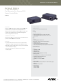
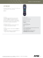
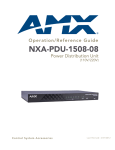
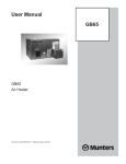
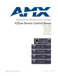
ICSLan Device Control Boxes.......................................... 388 – 397
Power and Sync Sensors.................................................. 398 – 399
Power Distribution............................................................ 400 – 403
Uninterruptible Power Supplies....................................... 404 – 406
Power Controllers............................................................. 407 – 409
Bus Strips, Terminal Adapters and Capture Devices...... 410 – 411
Mounting Brackets..................................................................... 412
Power Supplies and PoE.................................................. 413 – 417
Cables............................................................................... 418 – 420
Novara Remote Control............................................................. 421
control system accessories
INTRO D U CTION c o n t r o l s y s t e m a c c e s s o r i e s
THE PERFECT ACCESSORIES
Reliable, Professional Grade Components to Ensure Effective, Efficient Installations
Having the right accessories ensures smooth and efficient installations. And with AMX accessories, you can count on high
quality products and out-of-the-box compatibility with other AMX products. Power supplies are a particularly important
component of any installation – providing adequate voltage – especially on long cable runs. Other accessories include input
sensors, uninterruptable power supplies, contact closures, terminal adapters, bus strips, mounting brackets, and cabling.
SYSTEM DIAGRAM
386
Control System Accessories are the glue that bind an installation
Satellite Receiver even though there is only 1-way control (IR). The
together. In this application, the Dual Power and Video Sync
ABS AxLink Bus Strip allows the NetLinx Master to connect to
sensors allow the NetLinx Controller to determine the state of the
more than 250 AxLink devices (requires multiple bus strips).
US S A L ES A ND S U PPORT 8 0 0 . 2 2 2 . 0 1 9 3 • I NTER NATI ONA L S A L ES A ND S U PPORT +1 . 4 6 9 . 6 2 4 . 74 0 0 • www.a m x.c o m
© January 2013 AMX. All rights reserved. AMX does not assume responsibility for any errors or omissions.
INTRO D U CTION c o n t r o l s y s t e m a c c e s s o r i e s
The Anterus Radio Frequency Identification (RFID) product line provides real time tracking of assets/devices and
people. Anterus can be a stand-alone solution or integrated into a control system to track assets or people. Asset/
device tracking reduces theft with customized alerts and collects location and usage data to effectively manage and
budget future needs. Personnel tags can trigger environments like lighting or music based on individual preferences or
deliver customized messages in retail or entertainment environments.
SYSTEM DIAGRAM (cont.)
Another example of some of the unique accessories offered by
to avoid system down time and maximizing your technology
AMX is Uninterruptible Power Supplies. They protect AMX control
investment.
systems from lightning, power surges and power loss helping
3000 R E S EARCH D RIVE, RICH ARDSON, TX 75082 • 800.222.0193 • 469.624.7 1 5 3 f a x • TEC H NI C A L S U PPORT 8 0 0 . 9 3 2 . 6 9 9 3
© January 2013 AMX. All rights reserved. AMX does not assume responsibility for any errors or omissions.
387
control system accessories
EXB-IRS4
ICSLan IR/S Interface,
4 IR/S and 4 Inputs
(FG2100-23)
OVERVIEW
DEALER BENEFITS
ICSLan Device Control Boxes allow users to manage devices
•Standard, Ethernet-Based Interface – Familiar installation
remotely from a Controller over an Ethernet network. This
provides a beautifully simple method for a centralized control
environment allowing users to share a controller among multiple
smaller rooms versus controllers in every room. Ethernet has
become the industry standard for connecting devices and the
ICSLan Device Control Boxes make it easy to introduce control
methodology using standard switches rather than proprietary
distribution hardware
•Easy to Program – Programming is identical to any other device
port on the Controller
•Easy to Install – Compact size, Power over Ethernet and
compatible with any AMX Central Controller
to equipment such as projectors located extended distances
from a Controller. Additionally, the number of ports on an AMX
CUSTOMER BENEFITS
Controller can be expanded when all ports are fully populated.
•Control Any Device – Provides the ability to control devices that
Because they employ Native NetLinx technology, it is extremely
may be far from a controller
simple to add an EXB to an AMX installation.
•Cost Effective Solution for Smaller Rooms – Leverage the
COMMON APPLICATION
•Out of Sight – Compact design makes it easy to hide for a
power of a single central controller across multiple rooms
Conference rooms, classroom or auditoriums where a single
clean, elegant look
controller is used to manage multiple devices such as projectors
spread throughout a facility or to add additional ports to an AMX
Central Controller.
T RAI NI NG AVAI LABLE
Fo r i m po rt a nt i nst a l l a t i o n, c o nf i gura t i o n a nd pro g r a m m in g t e ch n iq u e s ,
A M X U ni v e rsi t y t ra i ni ng i s a v a i l a bl e . J ust v i si t ww w.a mx.c o m/ t ra i n i n g
FEATURES
•Enable Ports over Ethernet – Provides a future proof solution to
add ports anywhere
•Easy to Program – Programming is identical to any other device
ports on the Controller
•Power over Ethernet – Eliminate the need for a power source at
REV I T BI M
Thi s pro duc t i s pa rt o f t he A ut o de sk R e v i t da t a ba s e a n d ca n b e
spe c i f i e d i n de si gns f o r B ui l di ng I nf o rm a t i o n M o d e lin g ( B IM) . D o wn lo a d
t he a sso c i a t e d R e v i t . rf a f i l e f ro m t he A ut o de sk S E E K We b s it e . It is
a l so se a rc ha bl e unde r ‘ A M X’ i n a n y A ut o de sk a pp lica t io n .
the install location
•Small Form Factor – Compact design makes it easy to hide for a
clean installation
•NetLinx Studio Tools – Configuration tools make ICSLan Device
Control Boxes easy to deploy
388
US S A L ES A ND S U PPORT 8 0 0 . 2 2 2 . 0 1 9 3 • I NTER NATI ONA L S A L ES A ND S U PPORT +1 . 4 6 9 . 6 2 4 . 74 0 0 • www.a m x.c o m
© January 2013 AMX. All rights reserved. AMX does not assume responsibility for any errors or omissions.
E X B - IRS 4 c e n t r a l CONTROLLERS
SPECIFICATIONS
DIMENSIONS (HWD)
•1” x 4 3/8” x 5 1/8” (2.5 cm cm x 11.1 cm x 13.00 cm)
•RU: 1
WEIGHT
1 lb (454 g)
POWER
•PoE Powered - No local Power Supply needed
•Typical power draw: 1.9 Watts
•Max power draw: 2.4 Watts
OPERATION
•Four IR / Serial control ports, 20KHz - 1.14MHz
•Four input ports for sensing contact closure
STATUS LEDs
•1 Green LED shows connection and power status
•1 Green LED shows Ethernet Link status and activity
•4 Red LEDs (1 per IR port) show IR transmit (TX) data activity
•4 Yellow LEDs (1 per input port) show input activity
CONNECTIONS / WIRING
•1 RJ-45 ICS-LAN Ethernet Connector
•1 8-Pin 3.5mm captive-screw terminal for I/R ports
•1 6-Pin 3.5mm captive-screw terminal for inputs
CERTIFICATIONS
•FCC Part 15 Class B
•C-Tick CISPR 22 Class B
•VCCI CISPR 22 Class B
•CE EN 55022 Class B
•CB Scheme IEC 60950-1
•cULus UL 60950-1
RECOMMENDED ACCESSORIES
DESCRIPTION
PART #
CC-NIRC
NXA-ENET8-2POE
PS-POE-AF
AVB-VSTYLE-SURFACE-MNT
AVB-VSTYLE-RMK
AVB-VSTYLE-POLE-MNT
CC-NIRC
Gigabit Ethernet Switch
PoE Injector
V Style Module Surface Mount
V Style Module Tray / Tray with fill plates
V Style Module Pole Mount
(CC-NIRC)420
(FG2178-63)
444
(FG423-80)
416
(FG1010-722)
542
(FG1010-720/721)
542
(FG1010-723)
543
3000 R E S EARCH D RIVE, RICH ARDSON, TX 75082 • 800.222.0193 • 469.624.7 1 5 3 f a x • TEC H NI C A L S U PPORT 8 0 0 . 9 3 2 . 6 9 9 3
© January 2013 AMX. All rights reserved. AMX does not assume responsibility for any errors or omissions.
PAGE #
389
control system accessories
EXB-COM2
ICSLan Serial Interface, 2 Ports
(FG2100-22)
OVERVIEW
DEALER BENEFITS
ICSLan Device Control Boxes allow users to manage devices
•Standard, Ethernet-Based Interface – Familiar installation
remotely from a Controller over an Ethernet network. This
provides a beautifully simple method for a centralized control
environment allowing users to share a controller among multiple
smaller rooms versus controllers in every room. Ethernet has
become the industry standard for connecting devices and the
ICSLan Device Control Boxes make it easy to introduce control
methodology using standard switches rather than proprietary
distribution hardware
•Easy to Program – Programming is identical to any other device
port on the Controller
•Easy to Install – Compact size, Power over Ethernet and
compatible with any AMX Central Controller
to equipment such as projectors located extended distances
from a Controller. Additionally, the number of ports on an AMX
CUSTOMER BENEFITS
Controller can be expanded when all ports are fully populated.
•Control Any Device – Provides the ability to control devices that
Because they employ Native NetLinx technology, it is extremely
may be far from a controller
simple to add an EXB to an AMX installation.
•Cost Effective Solution for Smaller Rooms – Leverage the
COMMON APPLICATION
•Out of Sight – Compact design makes it easy to hide for a
power of a single central controller across multiple rooms
Conference rooms, classroom or auditoriums where a single
clean, elegant look
controller is used to manage multiple devices such as projectors
spread throughout a facility or to add additional ports to an AMX
Central Controller.
T RAI NI NG AVAI LABLE
Fo r i m po rt a nt i nst a l l a t i o n, c o nf i gura t i o n a nd pro g r a m m in g t e ch n iq u e s ,
A M X U ni v e rsi t y t ra i ni ng i s a v a i l a bl e . J ust v i si t ww w.a mx.c o m/ t ra i n i n g
FEATURES
•Enable Ports over Ethernet – Provides a future proof solution to
add ports anywhere
•Easy to Program – Programming is identical to any other device
ports on the Controller
•Power over Ethernet – Eliminate the need for a power source at
REV I T BI M
Thi s pro duc t i s pa rt o f t he A ut o de sk R e v i t da t a ba s e a n d ca n b e
spe c i f i e d i n de si gns f o r B ui l di ng I nf o rm a t i o n M o d e lin g ( B IM) . D o wn lo a d
t he a sso c i a t e d R e v i t . rf a f i l e f ro m t he A ut o de sk S E E K We b s it e . It is
a l so se a rc ha bl e unde r ‘ A M X’ i n a n y A ut o de sk a pp lica t io n .
the install location
•Small Form Factor – Compact design makes it easy to hide for a
clean installation
•NetLinx Studio Tools – Configuration tools make ICSLan Device
Control Boxes easy to deploy
390
US S A L ES A ND S U PPORT 8 0 0 . 2 2 2 . 0 1 9 3 • I NTER NATI ONA L S A L ES A ND S U PPORT +1 . 4 6 9 . 6 2 4 . 74 0 0 • www.a m x.c o m
© January 2013 AMX. All rights reserved. AMX does not assume responsibility for any errors or omissions.
E X B - COM 2 c e n t r a l CONTROLLERS
SPECIFICATIONS
DIMENSIONS (HWD)
•1” x 4 3/8” x 5 1/8” (2.5 cm cm x 11.1 cm x 13.00 cm)
•RU: 1
WEIGHT
1 lb (454 g)
POWER
•PoE Powered - No local Power Supply needed
•Power draw: 1.9 Watts
OPERATION
•One RS-232/422/485 control port, supports XON/XOFF, CTS/RTS, 300 - 115.2K
Baud
•One RS-232 control port, supports CTS/RTS, 300 - 115.2K Baud
STATUS LEDs
•1 Green LED shows connection and power status
•1 Green LED shows Ethernet Link status and activity
•2 Red LEDs (1 per COM port) show serial transmit (TX) data activity
•2 Yellow LEDs (1 per COM port) show serial receive (RX) data activity
CONNECTIONS / WIRING
•1 RJ-45 ICS-LAN Ethernet Connector
•1 10-Pin 3.5mm captive-screw terminal (RS-232/422/485 port)
•1 5-Pin 3.5mm captive-screw terminal (RS-232 port)
CERTIFICATIONS
•FCC Part 15 Class B
•C-Tick CISPR 22 Class B
•VCCI CISPR 22 Class B
•CE EN 55022 Class B
•CB Scheme IEC 60950-1
•cULus UL 60950-1
RECOMMENDED ACCESSORIES
DESCRIPTION
PART #
PAGE #
NXA-ENET8-2POE
PS-POE-AF
AVB-VSTYLE-SURFACE-MNT
AVB-VSTYLE-RMK
AVB-VSTYLE-POLE-MNT
Gigabit Ethernet Switch
PoE Injector
V Style Module Surface Mount
V Style Module Tray / Tray with fill plates
V Style Module Pole Mount
(FG2178-63)
(FG423-80)
(FG1010-722)
(FG1010-720/721)
(FG1010-723)
444
416
542
542
543
3000 R E S EARCH D RIVE, RICH ARDSON, TX 75082 • 800.222.0193 • 469.624.7 1 5 3 f a x • TEC H NI C A L S U PPORT 8 0 0 . 9 3 2 . 6 9 9 3
© January 2013 AMX. All rights reserved. AMX does not assume responsibility for any errors or omissions.
391
control system accessories
EXB-REL8
ICSLan Relay Interface, 8 Channels
(FG2100-20)
OVERVIEW
DEALER BENEFITS
ICSLan Device Control Boxes allow users to manage devices
•Standard, Ethernet-Based Interface – Familiar installation
remotely from a Controller over an Ethernet network. This
provides a beautifully simple method for a centralized control
environment allowing users to share a controller among multiple
smaller rooms versus controllers in every room. Ethernet has
become the industry standard for connecting devices and the
ICSLan Device Control Boxes make it easy to introduce control
methodology using standard switches rather than proprietary
distribution hardware
•Easy to Program – Programming is identical to any other device
port on the Controller
•Easy to Install – Compact size, Power over Ethernet and
compatible with any AMX Central Controller
to equipment such as projectors located extended distances
from a Controller. Additionally, the number of ports on an AMX
CUSTOMER BENEFITS
Controller can be expanded when all ports are fully populated.
•Control Any Device – Provides the ability to control devices that
Because they employ Native NetLinx technology, it is extremely
may be far from a controller
simple to add an EXB to an AMX installation.
•Cost Effective Solution for Smaller Rooms – Leverage the
COMMON APPLICATION
•Out of Sight – Compact design makes it easy to hide for a
power of a single central controller across multiple rooms
Conference rooms, classroom or auditoriums where a single
clean, elegant look
controller is used to manage multiple devices such as projectors
spread throughout a facility or to add additional ports to an AMX
Central Controller.
T RAI NI NG AVAI LABLE
Fo r i m po rt a nt i nst a l l a t i o n, c o nf i gura t i o n a nd pro g r a m m in g t e ch n iq u e s ,
A M X U ni v e rsi t y t ra i ni ng i s a v a i l a bl e . J ust v i si t ww w.a mx.c o m/ t ra i n i n g
FEATURES
•Enable Ports over Ethernet – Provides a future proof solution to
add ports anywhere
•Easy to Program – Programming is identical to any other device
ports on the Controller
•Power over Ethernet – Eliminate the need for a power source at
REV I T BI M
Thi s pro duc t i s pa rt o f t he A ut o de sk R e v i t da t a ba s e a n d ca n b e
spe c i f i e d i n de si gns f o r B ui l di ng I nf o rm a t i o n M o d e lin g ( B IM) . D o wn lo a d
t he a sso c i a t e d R e v i t . rf a f i l e f ro m t he A ut o de sk S E E K We b s it e . It is
a l so se a rc ha bl e unde r ‘ A M X’ i n a n y A ut o de sk a pp lica t io n .
the install location
•Small Form Factor – Compact design makes it easy to hide for a
clean installation
•NetLinx Studio Tools – Configuration tools make ICSLan Device
Control Boxes easy to deploy
392
US S A L ES A ND S U PPORT 8 0 0 . 2 2 2 . 0 1 9 3 • I NTER NATI ONA L S A L ES A ND S U PPORT +1 . 4 6 9 . 6 2 4 . 74 0 0 • www.a m x.c o m
© January 2013 AMX. All rights reserved. AMX does not assume responsibility for any errors or omissions.
E X B - REL 8 c e n t r a l CONTROLLERS
SPECIFICATIONS
DIMENSIONS (HWD)
•1” x 4 3/8” x 5 1/8” (2.5 cm cm x 11.1 cm x 13.00 cm)
•RU: 1
WEIGHT
1.02 lb (463 g)
POWER
•PoE Powered - No local Power Supply needed
•Typical power draw: 1.9 Watts
•Max power draw: 3.4 Watts
OPERATION
Eight relays, 1A @ 24VAC / 28VDC
STATUS LEDs
•1 Green LED shows connection and power status
•1 Green LED shows Ethernet Link status and activity
•8 Red LEDs (1 per relay) show relay activity
CONNECTIONS / WIRING
•1 RJ-45 ICS-LAN Ethernet Connector
•2 8-Pin 3.5mm captive-screw terminals
CERTIFICATIONS
•FCC Part 15 Class B
•C-Tick CISPR 22 Class B
•VCCI CISPR 22 Class B
•CE EN 55022 Class B
•CB Scheme IEC 60950-1
•cULus UL 60950-1
RECOMMENDED ACCESSORIES
DESCRIPTION
PART #
PAGE #
NXA-ENET8-2POE
PS-POE-AF
AVB-VSTYLE-SURFACE-MNT
AVB-VSTYLE-RMK
AVB-VSTYLE-POLE-MNT
Gigabit Ethernet Switch
PoE Injector
V Style Module Surface Mount
V Style Module Tray / Tray with fill plates
V Style Module Pole Mount
(FG2178-63)
(FG423-80)
(FG1010-722)
(FG1010-720/721)
(FG1010-723)
444
416
542
542
543
3000 R E S EARCH D RIVE, RICH ARDSON, TX 75082 • 800.222.0193 • 469.624.7 1 5 3 f a x • TEC H NI C A L S U PPORT 8 0 0 . 9 3 2 . 6 9 9 3
© January 2013 AMX. All rights reserved. AMX does not assume responsibility for any errors or omissions.
393
control system accessories
EXB-I/O8
ICSLan Input/Output Interface,
8 Channels
(FG2100-21)
OVERVIEW
DEALER BENEFITS
ICSLan Device Control Boxes allow users to manage devices
•Standard, Ethernet-Based Interface – Familiar installation
remotely from a Controller over an Ethernet network. This
provides a beautifully simple method for a centralized control
environment allowing users to share a controller among multiple
smaller rooms versus controllers in every room. Ethernet has
become the industry standard for connecting devices and the
ICSLan Device Control Boxes make it easy to introduce control
methodology using standard switches rather than proprietary
distribution hardware
•Easy to Program – Programming is identical to any other device
port on the Controller
•Easy to Install – Compact size, Power over Ethernet and
compatible with any AMX Central Controller
to equipment such as projectors located extended distances
from a Controller. Additionally, the number of ports on an AMX
CUSTOMER BENEFITS
Controller can be expanded when all ports are fully populated.
•Control Any Device – Provides the ability to control devices that
Because they employ Native NetLinx technology, it is extremely
may be far from a controller
simple to add an EXB to an AMX installation.
•Cost Effective Solution for Smaller Rooms – Leverage the
COMMON APPLICATION
•Out of Sight – Compact design makes it easy to hide for a
power of a single central controller across multiple rooms
Conference rooms, classroom or auditoriums where a single
clean, elegant look
controller is used to manage multiple devices such as projectors
spread throughout a facility or to add additional ports to an AMX
Central Controller.
T RAI NI NG AVAI LABLE
Fo r i m po rt a nt i nst a l l a t i o n, c o nf i gura t i o n a nd pro g r a m m in g t e ch n iq u e s ,
A M X U ni v e rsi t y t ra i ni ng i s a v a i l a bl e . J ust v i si t ww w.a mx.c o m/ t ra i n i n g
FEATURES
•Enable Ports over Ethernet – Provides a future proof solution to
add ports anywhere
•Easy to Program – Programming is identical to any other device
ports on the Controller
•Power over Ethernet – Eliminate the need for a power source at
REV I T BI M
Thi s pro duc t i s pa rt o f t he A ut o de sk R e v i t da t a ba s e a n d ca n b e
spe c i f i e d i n de si gns f o r B ui l di ng I nf o rm a t i o n M o d e lin g ( B IM) . D o wn lo a d
t he a sso c i a t e d R e v i t . rf a f i l e f ro m t he A ut o de sk S E E K We b s it e . It is
a l so se a rc ha bl e unde r ‘ A M X’ i n a n y A ut o de sk a pp lica t io n .
the install location
•Small Form Factor – Compact design makes it easy to hide for a
clean installation
•NetLinx Studio Tools – Configuration tools make ICSLan Device
Control Boxes easy to deploy
394
US S A L ES A ND S U PPORT 8 0 0 . 2 2 2 . 0 1 9 3 • I NTER NATI ONA L S A L ES A ND S U PPORT +1 . 4 6 9 . 6 2 4 . 74 0 0 • www.a m x.c o m
© January 2013 AMX. All rights reserved. AMX does not assume responsibility for any errors or omissions.
E X B - I / O 8 c e n t r a l CONTROLLERS
SPECIFICATIONS
DIMENSIONS (HWD)
•1” x 4 3/8” x 5 1/8” (2.5 cm cm x 11.1 cm x 13.00 cm)
•RU: 1
WEIGHT
1 lb (454 g)
POWER
•PoE Powered - No local Power Supply needed
•Power draw: 1.9 Watts
OPERATION
Eight Input/Output channels
STATUS LEDs
•1 Green LED shows connection and power status
•1 Green LED shows Ethernet Link status and activity
•8 Yellow LEDs (1 per I/O) show Input/Output activity
CONNECTIONS / WIRING
•1 RJ-45 ICS-LAN Ethernet Connector
•1 10-Pin 3.5mm captive-screw terminal (RS-232/422/485 port)
CERTIFICATIONS
•FCC Part 15 Class B
•C-Tick CISPR 22 Class B
•VCCI CISPR 22 Class B
•CE EN 55022 Class B
•CB Scheme IEC 60950-1
•cULus UL 60950-1
RECOMMENDED ACCESSORIES
DESCRIPTION
PART #
PAGE #
NXA-ENET8-2POE
PS-POE-AF
AVB-VSTYLE-SURFACE-MNT
AVB-VSTYLE-RMK
AVB-VSTYLE-POLE-MNT
Gigabit Ethernet Switch
PoE Injector
V Style Module Surface Mount
V Style Module Tray / Tray with fill plates
V Style Module Pole Mount
(FG2178-63)
(FG423-80)
(FG1010-722)
(FG1010-720/721)
(FG1010-723)
444
416
542
542
543
3000 R E S EARCH D RIVE, RICH ARDSON, TX 75082 • 800.222.0193 • 469.624.7 1 5 3 f a x • TEC H NI C A L S U PPORT 8 0 0 . 9 3 2 . 6 9 9 3
© January 2013 AMX. All rights reserved. AMX does not assume responsibility for any errors or omissions.
395
control system accessories
EXB-MP1
ICSLan Multi-Port, 1 COM, 1 IR/S,
2 I/O, 1 IR RX
(FG2100-26)
OVERVIEW
DEALER BENEFITS
ICSLan Device Control Boxes allow users to manage devices
•Standard, Ethernet-Based Interface – Familiar installation
remotely from a Controller over an Ethernet network. This
provides a beautifully simple method for a centralized control
environment allowing users to share a controller among multiple
smaller rooms versus controllers in every room. Ethernet has
become the industry standard for connecting devices and the
ICSLan Device Control Boxes make it easy to introduce control
methodology using standard switches rather than proprietary
distribution hardware
•Easy to Program – Programming is identical to any other device
port on the Controller
•Easy to Install – Compact size, Power over Ethernet and
compatible with any AMX Central Controller
to equipment such as projectors located extended distances
from a Controller. Additionally, the number of ports on an AMX
CUSTOMER BENEFITS
Controller can be expanded when all ports are fully populated.
•Control Any Device – Provides the ability to control devices that
Because they employ Native NetLinx technology, it is extremely
may be far from a controller
simple to add an EXB to an AMX installation.
•Cost Effective Solution for Smaller Rooms – Leverage the
COMMON APPLICATION
•Out of Sight – Compact design makes it easy to hide for a
power of a single central controller across multiple rooms
Conference rooms, classroom or auditoriums where a single
clean, elegant look
controller is used to manage multiple devices such as projectors
spread throughout a facility or to add additional ports to an AMX
Central Controller.
T RAI NI NG AVAI LABLE
Fo r i m po rt a nt i nst a l l a t i o n, c o nf i gura t i o n a nd pro g r a m m in g t e ch n iq u e s ,
A M X U ni v e rsi t y t ra i ni ng i s a v a i l a bl e . J ust v i si t ww w.a mx.c o m/ t ra i n i n g
FEATURES
•Enable Ports over Ethernet – Provides a future proof solution to
add ports anywhere
•Easy to Program – Programming is identical to any other device
ports on the Controller
•Power over Ethernet – Eliminate the need for a power source at
REV I T BI M
Thi s pro duc t i s pa rt o f t he A ut o de sk R e v i t da t a ba s e a n d ca n b e
spe c i f i e d i n de si gns f o r B ui l di ng I nf o rm a t i o n M o d e lin g ( B IM) . D o wn lo a d
t he a sso c i a t e d R e v i t . rf a f i l e f ro m t he A ut o de sk S E E K We b s it e . It is
a l so se a rc ha bl e unde r ‘ A M X’ i n a n y A ut o de sk a pp lica t io n .
the install location
•Small Form Factor – Compact design makes it easy to hide for a
clean installation
•NetLinx Studio Tools – Configuration tools make ICSLan Device
Control Boxes easy to deploy
396
US S A L ES A ND S U PPORT 8 0 0 . 2 2 2 . 0 1 9 3 • I NTER NATI ONA L S A L ES A ND S U PPORT +1 . 4 6 9 . 6 2 4 . 74 0 0 • www.a m x.c o m
© January 2013 AMX. All rights reserved. AMX does not assume responsibility for any errors or omissions.
E X B - M P 1 c e n t r a l CONTROLLERS
SPECIFICATIONS
DIMENSIONS (HWD)
•1” x 3” x 4 13/16” (2.5 cm cm x 7.6 cm cm x 12.2 cm)
•RU: 1
POWER
•PoE Powered - No local Power Supply needed
•Power draw: 1.9 Watts
OPERATION
•One RS-232 control port, supports CTS/RTS, 300 - 115.2K Baud
•Two Input/Output channels
•One IR / Serial control port, 20KHz - 1.14MHz
•One IR Receiver port
STATUS LEDs
•1 Green LED shows connection and power status
•1 Green LED shows Ethernet Link status and activity
•1 Red LED shows serial transmit (TX) data activity
•1 Yellow LED shows serial receive (RX) data activity
•2 Yellow LEDs (1 per I/O) show Input/Output activity
•4 Red LEDs (1 per IR port) show IR transmit (TX) data activity
•4 Yellow LEDs (1 per I/O port) show I/O input activity
CONNECTIONS / WIRING
1 RJ-45 ICS-LAN Ethernet Connector
CERTIFICATIONS
•FCC Part 15 Class B
•C-Tick CISPR 22 Class B
•VCCI CISPR 22 Class B
•CE EN 55022 Class B
•CB Scheme IEC 60950-1
•cULus UL 60950-1
RECOMMENDED ACCESSORIES
DESCRIPTION
PART #
PAGE #
CC-NIRC
IR03
NXA-ENET8-2POE
PS-POE-AF
AVB-VSTYLE-SURFACE-MNT
AVB-VSTYLE-POLE-MNT
NetLinx IR Emitter Cable
External IR Receiver Module
Gigabit Ethernet Switch
PoE Injector
V Style Module Surface Mount
V Style Module Pole Mount
(FG10-000-11)
(FG-IR03)
(FG2178-63)
(FG423-80)
(FG1010-722)
(FG1010-723)
420
3000 R E S EARCH D RIVE, RICH ARDSON, TX 75082 • 800.222.0193 • 469.624.7 1 5 3 f a x • TEC H NI C A L S U PPORT 8 0 0 . 9 3 2 . 6 9 9 3
© January 2013 AMX. All rights reserved. AMX does not assume responsibility for any errors or omissions.
444
416
542
543
397
control system accessories
PCS2
Dual Power Current Sensor
(for US 110 VAC 3-pole receptacles)
(FG427)
OVERVIEW
SPECIFICATIONS
The PCS2 Dual Power Current Sensor detects the 110 VAC current
DIMENSIONS (HWD)
drawn by equipment plugged into the onboard AC receptacles,
• 1 1/2” x 5 1/2” x 5 1/2” (3.8 cm x 1.4 cm x 1.4 cm)
• RU: 1
and the LED status indicators assist with monitoring system
applications. The PCS2 features adjustable sensing levels for high
(full-on), low (standby), and no-power (off) power levels for up to
two devices and comes complete with a built-in power supply.
WEIGHT
1 lb, 12.8 oz (816 g)
POWER REQUIREMENT
common application
• 110 VAC @ 250 mA minimum
• 1200 W (10A) input power, fuse protected
• Attached US-style 3-prong 120 VAC power cord
The PCS2 is ideal for determining the status of controlled sources
ENCLOSURE
such as video projectors, monitors, AV receivers, DVD players and
Metal with black matte finish
other devices.
CONTROL PORTS
features
ENVIRONMENTAL
4 relay outputs (on and standby for each source), 1 A @ 28 VDC
Heat Dissipation Typical: 10.2 BTU/hr
• On and standby status LEDs for each source
CONNECTIONS
• Power LED
• On 1, 2: On sense relay output, 1 A @ 28 VDC
• Stby 1, 2: Standby sense relay output, 1 A @ 28 VDC
• Com 1, 2: Common for sense outputs
• AC 1, 2:
- Two US style 3-prong 110 VAC receptacles
- 1,200 W (10A) output power, fuse protected
• AC Power: US style 3-prong 110 VAC power cord
• Sensing for 20 mA, 10 A power current levels
• Two US-style 3-prong 120 VAC receptacles
A C LO SE R LOOK
CONNECTORS
120 VAC Inp u t
COMBINED OUTPUT 120 VAC 1200W 50/60 Hz
120 VAC
10 AMP
50/60 Hz
ON
COM
ON
STBY
COM
STBY
2
1
• 6-pin captive-screw terminal
• 3-prong, grounded, 120 VAC receptacle
DRY CLOSURE RELAY OUTPUTS
0.5 A @120 VAC or 1 A @ 28 VDC
AC 2
AC 1
CLASS 2 CIRCUIT ONLY
Volt a ge Sensi ng Out put Por ts
D ual 120 VAC Outputs
INDICATORS
• 2 Standby LEDs
• 2 On LEDs
• Power LED
LOAD SENSITIVITY
• 10 A 1200 W maximum (combined fuses)
• 20 mA 2.4 W minimum 120 W maximum
POWER
STANDBY
ON
AC 1
398
STANDBY
ON
AC 2
RECOMMENDED ACCESSORIES
DESCRIPTION
PART #
PAGE #
AC-RK Accessory Rack
(FG515)
410
US S A L ES A ND S U PPORT 8 0 0 . 2 2 2 . 0 1 9 3 • I NTER NATI ONA L S A L ES A ND S U PPORT +1 . 4 6 9 . 6 2 4 . 74 0 0 • www.a m x.c o m
© January 2013 AMX. All rights reserved. AMX does not assume responsibility for any errors or omissions.
control system accessories
VSS2
Video Sync Sensor
(FG5916-10)
OVERVIEW
SPECIFICATIONS
The Video Sync Sensor (VSS2) is equipped with two independent
DIMENSIONS (HWD)
signal detection channels. When a signal is present, each
• 1 1/2” x 5” x 5 5/16” (3.8 cm x 12.7 cm x 13.3 cm)
• RU: 1
detection channel initiates a logic-level output, and dual video
jacks for each channel allow loop-through operation. The VSS2
is an ideal power sensor for DVDs and other video sources, or to
provide a warning on loss of audio, video or RGB signal.
WEIGHT
10.9 oz (309 g)
POWER REQUIREMENT
12 VDC at 20 mA
ENCLOSURE
common application
Molded black matte plastic
Use the VSS2 to monitor the true power status of a VCR, tuner
or satellite receiver and track the video output of each source,
CONTROL PORTS
sending a logic signal to an input port. The output can also be
Two open-collector outputs for channels A and B drive a logic low when a video
signal is present
used to control other AMX closure-driven peripherals, such as the
FRONT PANEL
PC1 Power Controller.
features
• Detects presence of signal from 1 kHz to greater than 100 kHz
• 2 independent video sync sensing channels
• 2 RCA jacks for each channel to allow loop-through operation
• 2 solid-state outputs that send a logic low signal when sync
is present
• Front-panel LEDs that display on/off status for each channel
• Power: Green LED indicator
• Sense 1: Red LED lights when sync is present
• Sense 2: Red LED lights when sync is present
RESPONSE
• Video Level: 8 MHz, 800 mV typical
• Sensing:
- 1 kHz to 3 MHz (200 mV RMS minimum)
- 3 MHz to 20 MHz (600 mV RMS minimum)
- 20 MHz to 75 MHz (750 mV RMS minimum)
OUTPUT
• Compatible with all AMX solid-state and closure input ports
Open collector with internal pull up to 5 V and solid-state logic low when signal
is present
• Detection of audio, video, and high-resolution RGB signals
REAR PANEL
• Video 2: RCA jacks for OUT and IN
• Video 1: RCA jacks for OUT and IN
• Sense Out 1 and 2: 4-pin captive-wire terminal
• 12 VDC: 2-pin power supply jack
A C LO SE R LOOK
INCLUDES
• One 6-pin cable connector
• Two 4-pin cable connectors
• One 2-pin power connector
OPTIONS
12 VDC power supply, 20 mA minimum
Vi deo 1 a nd 2 Connector
Sens e Out
Connector
12 VD C Po w er
Supply Con n ecto r
RECOMMENDED ACCESSORIES
DESCRIPTION
PART #
PAGE #
AC-RK Accessory Rack
(FG515)
410
3000 R E S EARCH D RIVE, RICH ARDSON, TX 75082 • 800.222.0193 • 469.624.7 1 5 3 f a x • TEC H NI C A L S U PPORT 8 0 0 . 9 3 2 . 6 9 9 3
© January 2013 AMX. All rights reserved. AMX does not assume responsibility for any errors or omissions.
399
control system accessories
NXA-PDU-1508-8
Power Distribution Unit
110/220 VAC Power
(FG673-01)
OVERVIEW
The innovative Power Distribution Unit (PDU) now allows you to
control the rack as well as control the room. This PDU adds a basic
M AK I NG T EC HNOLOGY GREEN
The Po w e r Di st ri but i o n U ni t re duc e s e ne rg y usa ge b y e lim in a t in g t h e
e l e c t ri c i t y use d by c o m po ne nt s w he n t he y a re i n s t a n d b y m o d e .
level of control by allowing remote reset of devices via a power
cycle, reducing the need to send staff to a customer site. By
managing power delivery, the PDU monitors energy consumption
of each connected component and restricts power to any or
DI D YOU K NOW ?
The Po w e r Di st ri but i o n U ni t a l l o w s a re m o t e re boo t f o r d e vice s in t h e
ra c k re duc i ng o n-si t e se r v i c e c a l l s.
all devices when not in use. With 8 individually monitored and
controlled AC outlets, built-in 12 Volt power supply, 2 sets of 4
AxLink Bus Strips, and power monitoring for each outlet, the PDU
is flexible and can reduce wasteful standby power usage. Native
NetLinx control over AxLink integrates the PDU with AMX Control
WAT C H T HE V I DEO
S e e t he NXA -PDU -1 5 0 8 -8 i n a c t i o n, l i v e f ro m I nf o C o m m 2 0 1 0 ,
by w a t c hi ng t he v i de o pro f i l e o nl i ne a t :
www. am x . c om /as s ets /v i deos /NX A -P DU -1 5 0 8 -8 . mp 4
systems and Resource Management Suite (RMS).
COMMON APPLICATION
Ideal for commercial and residential installations wanting to
T RAI NI NG AVAI LABLE
Fo r i m po rt a nt i nst a l l a t i o n, c o nf i gura t i o n a nd pro g r a m m in g t e ch n iq u e s ,
A M X U ni v e rsi t y t ra i ni ng i s a v a i l a bl e . J ust v i si t ww w.a mx.c o m/ t ra i n i n g
reduce energy usage costs, minimize their carbon footprint
and protect valuable electronics. With AC and AxLink power,
current sensing, and available temperature monitoring, this
all-in-one easily adds both convenience and a Green element to
installations.
AWARD W I NNER
The Ne t L i nx Po w e r Di st ri but i o n U ni t (NXA -PDU -1 50 8 - 8 ) wa s a wa r d e d a
2 0 1 0 EXC ! TE A w a rd f ro m C ust o m R e t a i l e r a nd 2 0 1 1 P r o d u ct o f t h e ye a r
f ro m El e c t ro ni c H o use .
FEATURES
•Individually Controlled Outlets – Allows a remote reboot for
devices in the rack reducing on-site service calls
•Power Management of Connected Devices – Reduces standby
energy usage (vampire power/phantom load)
•Built-in Power Current Sensing on Each AC Outlet – Makes it
REV I T BI M
Thi s pro duc t i s pa rt o f t he A ut o de sk R e v i t da t a bas e a n d ca n b e
spe c i f i e d i n de si gns f o r B ui l di ng I nf o rm a t i o n M o d e lin g ( B IM) . D o wn lo a d
t he a sso c i a t e d R e v i t . rf a f i l e f ro m t he A ut o de sk S E E K We b s it e . It is
a l so se a rc ha bl e unde r ‘ A M X’ i n a n y A ut o de sk a pp lica t io n .
easy to tell if a device is powered on or off
•Switched and Monitored AxLink Bus Strips – Allows power and
switching of AxLink or 12V powered devices (in banks of four)
•Native NetLinx Device – Simplifies integration
400
C OUNT RY OF ORI GI N: UNI T ED S TAT ES
To sa t i sf y t he re qui re m e nt s/re gul a t i o ns o f e x i st i n g o r f u t u r e g o ve r n m e n t
pro gra m s, t hi s t w o -l e t t e r c o de i s be i ng pro v i de d t o d e s ig n a t e t h e
c o unt r y o f o ri gi n f o r t hi s pro duc t .
US S A L ES A ND S U PPORT 8 0 0 . 2 2 2 . 0 1 9 3 • I NTER NATI ONA L S A L ES A ND S U PPORT +1 . 4 6 9 . 6 2 4 . 74 0 0 • www.a m x.c o m
© January 2013 AMX. All rights reserved. AMX does not assume responsibility for any errors or omissions.
NXA-PDU-1508-8 control system accessories
3000 R E S EARCH D RIVE, RICH ARDSON, TX 75082 • 800.222.0193 • 469.624.7 1 5 3 f a x • TEC H NI C A L S U PPORT 8 0 0 . 9 3 2 . 6 9 9 3
© January 2013 AMX. All rights reserved. AMX does not assume responsibility for any errors or omissions.
401
NXA-PDU-1508-8 control system accessories
SPECIFICATIONS
AXLINK MASTER CONNECTOR:
•3.5 mm Phoenix (4-pin) AxLink connector provides connectivity to the NetLinx
Master (always on).
DIMENSIONS (HWD)
•1 3/16" x 17" x 9 11/16 (3.0 cm x 43.2 cm x 9.7 cm)
•RU: 1
AXLINK DEVICE CONNECTORS (8):
POWER
•Powered via 100-240 VAC, 50-60 Hz mains power on an IEC-320 C-14 connector
•Required voltage = 100 to 240 VAC, 47-63 Hz
•AC Current
- Input: 12 AMPS @ 110V - 120V
- Input: 10 AMPS @ 220V - 240V
- Outputs: 10 AMPS Single Outlet @ 110 VAC, 12 AMPS Max Unit Output
@ 110 VAC
- Outputs: 8 AMPS Single Outlet @ 220 VAC, 10 AMPS Max Unit Output
@ 220 VAC
FRONT PANEL COMPONENTS
3.5 mm Phoenix (4 pin) AxLink connectors provide connectivity to up to eight
AxLink devices two switched banks of four outputs each:
•Bank 1 contains AxLink connectors 1-4
•Bank 2 contains AxLink connectors 5-8
A 13.5 VDC, 6.5 A power supply is provided for the AxLink bus strip. The PDU
measures current draw of the AxLink power supply.
REMOTE TEMPERATURE SENSOR (RTS) INPUT
3.5 mm Phoenix (2 pin) connector provides connection to an (optional) Remote
Temperature Sensor (RTS). The NXA-PDU-1508-8 is compatible with the ENVVST-TSF Flush Mount Indoor Temperature Sensor, and the ENV-VST-TSO Outdoor
Temperature sensor.
AXLINK ADDRESS DIP SWITCH
MASTER RESET PUSHBUTTON
•The Master Reset pushbutton is a momentary breaker reset switch for the
AMX Master power connection
•Trippage of the reset switch causes a 0.5 second toggle on the AMX Master
AxLink power line
8-position DIP switch sets the AxLink device address for the unit.
ENCLOSURE
Steel, black powder coated finish
ENVIRONMENTAL
•Operating Temperature: 0°C to 40°C (32°F to 104°F)
•Operating Humidity: 5% to 85%, non-condensing
•Storage Temperature: -10°C to 60°C (14°F - 140°F)
AXLINK STATUS LED:
Green LED lights to indicate AxLink communication activity
•ON - power, no master connection
•OFF - no power
•Blink - powered, communicating with master
INCLUDED ACCESSORIES
8 green LEDs illuminate when the associated Power Outlet (#1 - #8) is in use.
•ENV-VST-TSO ViewStat Outdoor Temperature Sensor (FG2050-22)
•EC-320 C-13 to NEMA 5-15P cable
•Removable rack ears
AXLINK BUS STATUS LEDs
OTHER AMX EQUIPMENT
OUTLET STATUS LEDs
2 red LEDs light to indicate status (on/off) for AxLink Bus Strips 1-2.
These LEDs illuminate when the associated AxLink Bus Strip ((#1 or (#2) on the
PDU is in use.
•A xLink Bus Strip 1 contains AxLink connectors 1 - 4
•A xLink Bus Strip 2 contains AxLink connectors 5 - 8
•ENV-VST-TSF Indoor Temperature Sensor (FG2050-21)
•C13 to C14 Power Cable (FG10-673-01)
•NEMA to C14 Power Cable (FG10-673-02)
REAR PANEL COMPONENTS
INTERNATIONAL POWER INLET (1)
•100-240 VAC 50/60 Hz
•Connector Type: IEC C-14, 15A@120 VAC / 10A@240 VAC
•Intended for use with the included power cord (US Version Only)
INTERNATIONAL POWER OUTLETS (8)
•100-240 VAC 50/60 Hz
•Connector Type: IEC C-13, 10A
•Maximum load per outlet = 10A@120 VAC, 8A@240 VAC
•Maximum load per unit = 15A@120VAC, 10A@240 VAC
•Provides switching of mains power to each of the eight power outlets.
•Measures current on each AC power outlet, as well as the total current draw of
the entire PDU.
402
RECOMMENDED ACCESSORIES
DESCRIPTION
PART #
PAGE #
CC-C13-C14
CC-C14-NEMA
C13 to C14 Power Cable
C14 to NEMA Power Cable
(FG10-673-01)
(FG10-673-02)
403
403
US S A L ES A ND S U PPORT 8 0 0 . 2 2 2 . 0 1 9 3 • I NTER NATI ONA L S A L ES A ND S U PPORT +1 . 4 6 9 . 6 2 4 . 74 0 0 • www.a m x.c o m
© January 2013 AMX. All rights reserved. AMX does not assume responsibility for any errors or omissions.
control system accessories
CC-C13-C14
C13 to C14 Power Cable
(FG10-673-01)
OVERVIEW
The C13 to C14 Power Cable provides a convenient option to
connect a device to the NXA-PDU-1508-8.
CC-C14-NEMA
C14 to NEMA Power Cable
(FG10-673-02)
OVERVIEW
The C14 to NEMA Power Cable provides a convenient option to
connect a device to the NXA-PDU-1508-8.
3000 R E S EARCH D RIVE, RICH ARDSON, TX 75082 • 800.222.0193 • 469.624.7 1 5 3 f a x • TEC H NI C A L S U PPORT 8 0 0 . 9 3 2 . 6 9 9 3
© January 2013 AMX. All rights reserved. AMX does not assume responsibility for any errors or omissions.
403
control system accessories
NXA-UPS1500
Uninterruptible Power Supply
NXA-UPS1500/120 110-120 VAC
(FG678-15)
NXA-UPS1500/240 220-240 VAC
(FG678-20)
OVERVIEW
The NXA-UPS1500 Uninterruptible Power Supply is a necessity in
protecting AMX control systems and MAX servers from lightning,
power surges and power loss. Maximize your investment with the
D-T OOLS C ERT I FI ED P RODUC T
Thi s pro duc t c a n be f o und i n t he D-To o l s m a nuf a ct u r e r p r o d u ct
da t a ba se a nd spe c i f i e d a s a t hi rd pa rt y de v i c e w h e n b u ild in g a n d
pro po si ng a sy st e m usi ng D-To o l s S y st e m I nt e gra t o r s o f t wa r e .
smaller, more powerful UPS by AMX.
COMMON APPLICATION
The NXA-UPS1500 is ideal for residences and commercial
applications to protect equipment from lighting, power surges
C OUNT RY OF ORI GI N: C HI NA
To sa t i sf y t he re qui re m e nt s/re gul a t i o ns o f e x i st i n g o r f u t u r e g o ve r n m e n t
pro gra m s, t hi s t w o -l e t t e r c o de i s be i ng pro v i de d t o d e s ig n a t e t h e
c o unt r y o f o ri gi n f o r t hi s pro duc t .
and power loss.
FEATURES
• Large Capacity Backup Power: 1500 VA/900 W
• Smaller Form Factor: 2 U rack mount
• 110-120/220-240 VAC Support
• User Friendly LCD Display
• Pure Sine Wave Output on Backup Mode
• Advanced Battery Discharge Management
• Tower / Rack Convertible
404
US S A L ES A ND S U PPORT 8 0 0 . 2 2 2 . 0 1 9 3 • I NTER NATI ONA L S A L ES A ND S U PPORT +1 . 4 6 9 . 6 2 4 . 74 0 0 • www.a m x.c o m
© January 2013 AMX. All rights reserved. AMX does not assume responsibility for any errors or omissions.
NXA-UPS1500 control system accessories
A C LO SE R LOOK
RS2 3 2 C o mmuni ca t i o n Por t
DIP Swi t ch
USB Communic ation
Por t
I n p u t Br eak er
Ou tp u t Br eak er
RJ -4 5 Po r ts
Ex ter n al Batter y
(N e tw or k Su r g e P r o tecti o n )
Ter m i n al
I n p u t Po w er
S o ck et (I n l et)
3000 R E S EARCH D RIVE, RICH ARDSON, TX 75082 • 800.222.0193 • 469.624.7 1 5 3 f a x • TEC H NI C A L S U PPORT 8 0 0 . 9 3 2 . 6 9 9 3
© January 2013 AMX. All rights reserved. AMX does not assume responsibility for any errors or omissions.
Po w er Ou tl ets
405
NXA-UPS1500 control system accessories
SPECIFICATIONS
DIMENSIONS (HWD)
DISPLAY LCD
• 3 7/16” x 17 5/16” x 19” (8.8 cm x 44 cm x 48.2 cm)
• RU: 2
• Load level (%)
• Battery level (%)
• Bypass
• AVR-Boost/AVR Buck
• Battery Low/Replace/Fault
• UPS Fault
• Site Wiring Fault
• Overload
WEIGHT
70.3 lbs (31.9 kg)
INPUT
• Voltage Window (DIP Switch selectable):
- 120V version (FG678-15): 110/115/120 VAC +35% – -32%
- 240V version (FG678-20): 220/230/240 VAC +35% – -32%
• Frequency: 45 – 65Hz (50/60Hz auto-sensing)
OVERLOAD PROTECTION
• AC Mode: >110% Buzzer continuously alarms, and shuts down in 10 minutes.
• Inverter Mode: >120% Buzzer continuously alarms, and shuts down in
10 seconds.
OUTPUT
• Voltage Window (AC Mode):
- 120V version (FG678-15): 110/115/120 VAC +8% – -12%
- 240V version (FG678-20): 220/230/240 VAC +8% – -12%
• Voltage Window (INV Mode):
- 120V version (FG678-15): 110/115/120 VAC +/-5%
- 240V version (FG678-20): 220/230/240 VAC +/-5%
• Max Output Current:
- 120V: 14A (continuous)
- 240V: 7A (continuous)
• Capacity (VA/W): 1500/900
• Wave Form: Pure sine wave
• Frequency: 50Hz/60Hz +/-0.1Hz
• Transfer Time: 2 ms typical
• Autonomy: > 8 min.
• DC Start: Yes
SHORT CIRCUIT PROTECTION
• AC Mode: Breaker and electronic circuit
• Max short circuit output current:
- 120V: 50A, 8 cycles (Inverter Mode short circuit current limitation)
- 240V: 25A, 8 cycles (Inverter Mode short circuit current limitation)
SELF-DIAGNOSTICS
Upon Power-on
ALARMS
• Line Failure
• Battery Low
• Overload and Fault
ENVIRONMENTAL
BATTERY
• Type: 12V, sealed lead acid maintenance-free
• Capacity: 9AH
• Quantity: 4 batteries required
• Voltage:
- 120V version (FG678-15): 24 VDC
- 240V version (FG678-20): 48 VDC
• InRush Current:
- 120V: < 40A
- 240V: > 20A
• Recharge Time: 2 – 4 hours to 90%
• Storage: Store at -15 to +30 °C (+5 to +86 °F), charge the UPS battery every
6 months / Store at +30 to +45 °C (+86 to +113 °F), charge the UPS battery
every 3 months.
• Temperature: 32° to 104°F (0 to 40° C)
• Operation Humidity: 95% RH Maximum, non-condensing
CONTROL COMMUNCATION
RS-232
CERTIFICATIONS
• EN50091-1-1: 1996 (Safety)
• FCC Part 15, Subpart B - Class A
• UL: YEDU.E166979
INCLUDED ACCESSORIES
• AC Input Power Cord
• Tower and rack-mounting accessories
LED INDICATORS
• Utility mode
• Backup mode
• Battery conditions
406
US S A L ES A ND S U PPORT 8 0 0 . 2 2 2 . 0 1 9 3 • I NTER NATI ONA L S A L ES A ND S U PPORT +1 . 4 6 9 . 6 2 4 . 74 0 0 • www.a m x.c o m
© January 2013 AMX. All rights reserved. AMX does not assume responsibility for any errors or omissions.
control system accessories
PC1
Power Controller, 10 A
(110 VAC only)
(FG670)
OVERVIEW
SPECIFICATIONS
The PC1 control provides one switched outlet for 120 VAC power
DIMENSIONS (HWD)
control with up to 1200 W of equipment power.
• 1 1/2” x 5 1/2” x 5 1/2” (3.8 cm x 14 cm x 14 cm)
• RU: 1
COMMON APPLICATION
WEIGHT
Ideal for giving power control over devices that may not be easily
controlled via Infrared or other control signal types.
features
1 lb, 12 oz (793 g)
POWER REQUIREMENT
• Power Input: 105 to 125 VAC, 3 watts maximum (internal electronics)
• Power Outputs: 1 switched 3-wire sockets, 120 VAC, 1,200 watts total
CONTROL PORTS
• Front-panel on/off button with status LED
• Either one latched or two momentary closures for discrete on and off, or one
momentary closure for toggling on and off
• Switched AC receptacle, 10 A at 120 VAC
• DIP switch to set closure mode
D-T OO LS C E RT IFIE D P ROD UCT
This pr oduc t c an be fo u nd i n th e D-To o l s ma nufa cture r p ro d uct
da tabas e and s pec ifie d a s a thi rd p a rty de vi ce wh e n b ui l di ng a n d
pr opos ing a s y s tem usi ng D-To o l s Syste m I n te gra to r so ftwa re .
LOAD FUSE
Internal 10 A (load capacity)
CONTROL INPUTS
Remote control contact and switch closure
ENCLOSURE
Metal with black matte finish
PRODUCT TYPE
AC switched power control unit
A C LO SE R LOOK
FRONT PANEL
D IP s w itc he s fo r
contr ol s ettin g s
P ushbut t o n Po wer Switch w ith Status LED
• AC1 power switch controls power to a switched
socket. The pushbutton is a latching on/off switch. The LED in the pushbutton
indicates that socket power is ON
• DIP Switch: Controls the AC1 (and AC2) push button operating mode,
depending on the setting of the switches
BACK PANEL
• AC Power Input: 3-conductor line cord providing 120 VAC power to the power
control unit and to switched power sockets
• Switched Power: Socket for control of external equipment having a total power
load of 1,200 watts. An internal 10 A load fuse is provided (The PC2 has 2
power sockets)
• Control: 4-pin captive-wire connector providing remote operation of the power
control units. Terminals accept 24 – 12 AWG wire
POWER CORD
6 ft (1.83 m) cord with 3-wire grounded plug
4- p i n ca pt i ve-wi re co nnector
f o r po wer co nt ro l
120 VAC Output
120 VAC Input
RECOMMENDED ACCESSORIES
DESCRIPTION
PART #
PAGE #
AC-RK Accessory Rack
(FG515)
410
3000 R E S EARCH D RIVE, RICH ARDSON, TX 75082 • 800.222.0193 • 469.624.7 1 5 3 f a x • TEC H NI C A L S U PPORT 8 0 0 . 9 3 2 . 6 9 9 3
© January 2013 AMX. All rights reserved. AMX does not assume responsibility for any errors or omissions.
407
control system accessories
UPC20+
Universal Power/Motor Controller, 20 A
(110/220 VAC input)
(FG672)
OVERVIEW
Designed for conduit installation, the Universal Power/Motor
Controller, 20 A (110/220 VAC input) is a dual 20-amp AC power
HELP FUL HI NT
I f U PC 2 0 + i s po w e re d up w he n c ha nge s a re m a de t o D ip S wit ch s e t t i ngs, t he n po w e r m ust be cy cl e d be f o re c ha nge s ca n t a k e e f f e ct .
and motor controller. Configure a wide range of power and motor
control modes for a full range of devices ranging from simple wall
panels with low voltage contact closure to large systems requiring
A C LOS ER LOOK
high voltage contact closure.
The UPC20+ supports two primary operating modes. In Motor
Control Mode, the two relays are automatically activated in
sequence with an adjustable delay from 0 to 90 seconds. In this
mode, there are three control options:
CAUTION
RISK OF ELECTRIC SHOCK - MORE THAN ONE
DISCONNECT SWITCH MAY BE REQUIRED TO DE-ENERGIZE
THE EQUIPMENT BEFORE SERVICING
GND
IMPORTANT
sequence: Up, Stop, Down, Stop and so on for each successive
5
6
SWITCH MUST
MATCH INPUT
VOLTAGE PRIOR
TO APPLYING
POWER TO UNIT
•Single Button Mode operates with one pushbutton in a
4
3
2
K2
1
P1
K1
H ig h v o lt a g e
wirin g
B L K 12 A W G
TO CIRCUIT BD
ELECTRONICS
USE COPPER ONLY
75°C INSULATION
B L K 1 2 AWG
button press.
•Two/Three Button Mode operates with two pushbuttons, one
for Up and one for Down and optionally one for stop.
Po w er S w i tch
(1 1 5 /2 3 0 VAC )
S p a d e t e rm in a l
b lo c k P 1
•Momentary On/Off operates the first relay only while the button
is pressed and then second the relay activates when the button
is released.
PB1
DI P s w i tch
two independent circuits with a combined total load of 20 Amps.
In this mode, there are three control options:
JP1
ON
the button is pressed. The relay is de-activated when the button
5
+12V
GND
GND
IN 1
RECEIVER
INPUT
CLASS 2 CIRCUIT ONLY
6 7
8
9
+12
4
IN 2
3
IN 4
2
IN 3
1
DATA
PART # 91-0672-01, REV F
•Momentary Power Mode operates the selected relay only while
I R r em o te co n tr o l
co n n ecti o n s
REMOTE
1 2 3 4
P2
LISTED
IND.CONT.EQ.
68WF
C
R
Jumper JP1
US
UPC20+
CONTROL
INPUTS
SEE INSIDE COVER FOR DETAILED WIRING
AND DIP SWITCH INFORMATION
NOTE: NO HIGH VOLTAGE THIS CONNECTION
is released.
CONTACT
In Power Control mode, the UPC20+ provides power control for
Te s t s wit c h e s
wit h s t a t u s L E D s
PB2
Richardson, Texas
800-222-0193
469-624-8000
•Latching Power Mode toggles between activating and deactivating the selected relay on each successive button press.
•Two Button On/Off Mode uses two buttons for each relay, one
to activate and one to deactivate.
features
• 1, 2 and 3-button logic modes
• Local test switches with status LEDs
• 120, 240, and 277 VAC control capability
• ETL listed
408
US S A L ES A ND S U PPORT 8 0 0 . 2 2 2 . 0 1 9 3 • I NTER NATI ONA L S A L ES A ND S U PPORT +1 . 4 6 9 . 6 2 4 . 74 0 0 • www.a m x.c o m
© January 2013 AMX. All rights reserved. AMX does not assume responsibility for any errors or omissions.
UPC20+ control system accessories
SPECIFICATIONS
DIMENSIONS (HWD)
HIGH VOLTAGE TERMINAL BLOCK (P1)
• 8 1/2” (10 1/2” (including flange) x 4 1/2” x 2 3/16” (22 cm (27 cm (including
flange) x 11 cm x 6 cm)
• RU: 5
High voltage input and output wiring for motor or power control.
LOW VOLTAGE AND CONTROL TERMINAL BLOCK (P2)
WEIGHT
Contact closure, open-collector or CMOS logic level remote control wiring
Inputs 5 - 8 are referenced to the common connection at pin 4
3 lbs (1.4 kg)
JUMPER JP1
POWER
Sets control mode of the unit to contact closure or remote sensor serial data
• Self-powered when used with 110/220 VAC applications
• Power input options (for control board):
- 120/240V ~, 50-60 Hz, 0.05/0.025A
- 12 VDC, 0.2A max
• Power output per relay
- 20A @ 120/240V ~, 50-60 Hz (RESISTIVE LOAD)
- 6A @ 277V ~, 50-60 Hz (FLUORESCENT BALLAST)
- 1 HP @ 120V ~, 50-60 Hz (INDUCTIVE LOAD)
- 2 HP @ 240V ~, 50-60 Hz (INDUCTIVE LOAD)
Total Current through both relays CANNOT exceed 20 amps
ENCLOSURE
Metal with black matte finish, knockouts for conduit
INPUTS
• 4 closure inputs, operation defined by mode
• One IR remote sensor input
• Motor Control mode alternates between the timed operation of the two
power relays
• Power Control mode allows independent control of both power relays
TEST SWITCHES (PB1 AND PB2)
Provides local operation of relays K1 and K2 for testing power circuits or motors
connected to the relay terminals. An LED indicates relay power applied
MOTOR TIME DELAY POTENTIOMETER (R8)
Only used in motor control modes. User adjusted for setting relay release time
between 0 and 90 seconds
DIP SWITCH (S2)
Provides selection of control mode options
CONTROL INPUTS
• 4 closure inputs; operation defined by mode
• Motor control mode alternates between the timed operation of the two
power relays
• Power control mode allows independent control of both power relays
CONTROL PORTS
(2) 2400 W power relays. Total combined current through both relays is 20 Amps
CERTIFICATIONS
UL, C-UL, CE
INPUT POWER SWITCH (S1)
Environmental
• Set this switch according to the high voltage wiring that will be connected to
terminals 5 and 6 on P1.
• Set switch S1 to the line input voltage value used before applying power to
the UPC20+
Operating/Storage Temperature: 55º C
RECOMMENDED ACCESSORIES
DESCRIPTION
PART #
PAGE #
PS2.8 2.8 A Power Supply
(FG423-05)
412
3000 R E S EARCH D RIVE, RICH ARDSON, TX 75082 • 800.222.0193 • 469.624.7 1 5 3 f a x • TEC H NI C A L S U PPORT 8 0 0 . 9 3 2 . 6 9 9 3
© January 2013 AMX. All rights reserved. AMX does not assume responsibility for any errors or omissions.
409
control system accessories
ABS
SPECIFICATIONS
AxLink Bus Strip
DIMENSIONS (HWD)
• 1 1/8” x 12” x 1 1/4” (2.9 cm x 30.5 cm x 3.2 cm)
• RU: 1
(FG960)
WEIGHT
5.8 oz (164.42 g)
POWER
12 VDC, 7 A max.
LED
Power indicator (Red)
MOUNTING OPTIONS
4” double-sided foam tape
OVERVIEW
With the ABS AxLink Bus Strip experience plug-and-play wiring,
a power (PWR) status LED, and 12 VDC power inputs. Perfect for
larger wiring runs the ABS simultaneously accepts in up to 10
AxLink terminals and connectors.
T RAI NI NG AVAI LABLE
Fo r i m po rt a nt i nst a l l a t i o n, c o nf i gura t i o n a nd pro g r a m m in g t e ch n iq u e s ,
A M X U ni v e rsi t y t ra i ni ng i s a v a i l a bl e . J ust v i si t ww w.a mx.c o m/ t ra i n i n g
COMMON APPLICATION
Ideal for combining up to 10 AxLink wiring runs.
features
• 12 VDC power status LED
A C LOS ER LOOK
• 10 4-pin AxLink connectors
• 1 2-pin power connector
• 4” double-sided foam tape
Ten 4 -p i n , cap ti v e-w i r e
Ax Li n k C o n n ecto r s
AC-RK
On e 2 -p i n , c a p t iv e - wire
p o w er c o n n e c t o r
SPECIFICATIONS
Accessory Rack Kit
DIMENSIONS (HWD)
• 1 3/4” x 19” x 1/2” (4.4 cm x 48.3 cm x 1.3 cm)
• RU: 1
(FG515)
T RAI NI NG AVAI LABLE
Fo r i m po rt a nt i nst a l l a t i o n, c o nf i gura t i o n a nd pro g r a m m in g t e ch n iq u e s ,
A M X U ni v e rsi t y t ra i ni ng i s a v a i l a bl e . J ust v i si t ww w.a mx.c o m/ t ra i n i n g
OVERVIEW
The Accessory Rack Kit holds up to three NetLinx modules and
measures only one rack unit in height.
410
D-T OOLS C ERT I FI ED P RODUC T
Thi s pro duc t c a n be f o und i n t he D-To o l s m a nuf a ct u r e r p r o d u ct
da t a ba se a nd spe c i f i e d a s a t hi rd pa rt y de v i c e w h e n b u ild in g a n d
pro po si ng a sy st e m usi ng D-To o l s S y st e m I nt e gra t o r s o f t wa r e .
US S A L ES A ND S U PPORT 8 0 0 . 2 2 2 . 0 1 9 3 • I NTER NATI ONA L S A L ES A ND S U PPORT +1 . 4 6 9 . 6 2 4 . 74 0 0 • www.a m x.c o m
© January 2013 AMX. All rights reserved. AMX does not assume responsibility for any errors or omissions.
control system accessories
IRIS
IR/Serial Data Capture Device
(FG5448)
OVERVIEW
SPECIFICATIONS
As a stand-alone self-contained unit, the IRIS captures IR or wired
DIMENSIONS (HWD)
function signals from a hand controller and instantly captures and
• 1 1/2” x 5 1/2” x 5 1/2” (3.8 cm x 14 cm x 14 cm)
• RU: 1
verifies the control functions, where they are transmitted to a PC
operating the IRLIB program. Designed with versatility in mind,
the IRIS captures IR functions from hand controllers for a wide
variety of audiovisual equipment such as monitors, VCRs, TVs, and
CD players.
WEIGHT
1.8 lbs (518.2 g)
POWER REQUIREMENT
12 VDC at 160 mA max
ENCLOSURE
Metal with black matte finish
features
CONTROL PORTS
• Large, 2-digit status LED display
• Configurable RS-232 port baud rate (300-9,600 baud)
• 12 VAC power supply
FRONT PANEL COMPONENTS
• IREdit software
QU IC K T IP
Us e the IR Ca ptur e and M a n a ge me n t to o l i n AM X's V i sua l Archi te ct so f t war e a pplic a tion to ca pture a nd ma na ge I R functi o ns vi a th e I RI S. R e f e r
to the Vis ualAr c hitect I n structi o n M a n ua l a n d o n l i ne h e l p fo r d e ta i l s.
A C LO SE R LOOK
Si gna l LE D
• IR sensor to receive IR codes
• IR serial input for wired IR codes
• DB-9 female connector for Axcess and PC communication
IR W indow
R ea dy L ED
Alphanume r ic
D is play
Ve r ify L ED
Up/ D ow n
Buttons
Send Button
• Signal LED: Red indicator that blinks when the IRIS unit is receiving
HC functions
• IR window: Captures HC functions
• Ready LED: Green indicator that lights when the IRIS unit is ready to receive
HC functions
• Verify: Red indicator that lights when the IRIS unit is ready to verify
HC functions
• Alphanumeric display: (2-digit) Red 7-segment alphanumeric display that
shows the capture mode and operating status
• Up: Increments the alphanumeric display by one and lights the red LED inside
the pushbutton
• Down: Decrements the display by one and lights the red LED inside
the pushbutton
• Send: Transmits captured HC functions to a PC running the IREdit software
program. The red LED inside the pushbutton lights when valid HC functions are
ready to send
REAR PANEL COMPONENTS
• 12 VDC/12 VAC connector: 2-pin (male) 12 VDC or 12 VAC power
supply connector.
• 8-pin data connector: Captures wired-IR HC functions. Connect the HC to the
IRE IN or WIRED IN pins.
• RS-232 connectors:
- DB-9 connector for data communications with a PC
- 6-pin RJ-11 modular connector for data communications. The RJ-11 connector
is only used with older SX-DCU+ products
12 V
C on n e ct o r
8 -pi n Data
C o nnect or
RS-232 D B-9
conne ctor
RS-232 6-pin RJ-1 1
conne ctor
3000 R E S EARCH D RIVE, RICH ARDSON, TX 75082 • 800.222.0193 • 469.624.7 1 5 3 f a x • TEC H NI C A L S U PPORT 8 0 0 . 9 3 2 . 6 9 9 3
© January 2013 AMX. All rights reserved. AMX does not assume responsibility for any errors or omissions.
411
control system accessories
AC-SMB
Surface Mounting Bracket
(FG525)
OVERVIEW
These L-shaped brackets can be oriented to align flush with either
the top or bottom surface and allow users to mount devices to
almost any flat surface; floor, ceiling, wall, table or wherever is
convenient for an installation. AC-SMB brackets can be used with
NI-700/900 controllers, MAX-CSE, MAX-CSD10, NXA-AVB,
NXA-AVB/ETHERNET, and IS-SPX-1000.
PS2.8
SPECIFICATIONS
13.5 VDC, 2.8 A Power Supply
with 2.1 mm Barrel Connector
DIMENSIONS (HWD)
• 4 5/8" x 2 5/16" x 1 1/2" (11.7 cm x 5.8 cm x 3.5 cm)
WEIGHT
(and included 5 mm Phoenix Connector)
1 lb (450 g)
(FG423-11)
• Input Voltage: 100-240 +10% VAC
• Input Frequency: 47-63 Hz
• Input Current:
- 0.9A MAX at 115 VAC + full load
- 0.6A MAX at 230 VAC + full load
• Output Voltage: 13.5 VDC
• Output Current: 2.8A (continuous power output is 35 W max)
POWER REQUIREMENT
ENCLOSURE
Molded black matte plastic, with captive 6-foot (1.83 m) output cord and IEC
male input power jack
RIPPLE AND NOISE
135 mV peak-to-peak @ full load
OVERVIEW
Perfect for 13.5 DC power with Axcess systems, the PS2.8 Power
PROTECTION
Supply is a Class 1 power supply. The PS2.8 is UL listed in addition
Over-voltage, over-current, short-circuit, transient and thermal. Switching
regulated, overload protected
to CSA and CE approved. The PS2.8 comes with both an attached
POWER INDICATOR
2-pin captive wire connector (5 mm) and a spare 3.5 mm captive
Green LED indicates the presence of DC on the output
wire connector. For your convenience, the PS2.8 also comes with a
CONNECTORS
with 5 mm Phoenix Connector.
• 2.1mm barrel plug
• Also includes 2-pin captive wire connector (5.0 mm)
FEATURES
INPUT POWER CORD
• Class 1 power supply
• UL listed
6-foot (1.83 m) IEC power cord terminated with a grounded Edison plug for AC
input
• CSA approved
CERTIFICATION
• CE approved
UL: US listed - Class 1 Power Supply, CSA approved, CE approved
ENVIRONMENTAL
T RA INING AVAILABLE
For im por tant ins ta l l a ti o n, co n fi gura ti o n a n d p ro g ra mmi n g te ch ni que s,
AMX Univ er s ity tr ain i ng i s a va i l a b l e . Ju st vi si t ww w.a mx.c om/tra i ni ng
412
Operating Temperature: 32ºF to 122ºF (0ºC to 50ºC)
INCLUDED ACCESSORIES
Single Universal input power cord (64-0009)
US S A L ES A ND S U PPORT 8 0 0 . 2 2 2 . 0 1 9 3 • I NTER NATI ONA L S A L ES A ND S U PPORT +1 . 4 6 9 . 6 2 4 . 74 0 0 • www.a m x.c o m
© January 2013 AMX. All rights reserved. AMX does not assume responsibility for any errors or omissions.
control system accessories
PSN2.8
PS3.0
13.5 VDC, 2.8 A Power Supply with
3.5 mm Phoenix Connector
12 VDC, 3.0 A Power Supply with
1.3 mm Barrel Plug
(FG423-17)
(FG423-30)
OVERVIEW
OVERVIEW
The PSN2.8 power supply provides 2.8 A of DC power for
The PS3.0 power supply provides 3.0 A of DC power for the
Modero Touch Panels. This is a Class 1 power supply; CSA and CE
MVP-5200i Modero Touch Panel and other NetLinx devices. This
approved and UL listed. This power supply has an attached mini
is a Class 1 power supply which is CE approved and UL listed.
2-pin captive wire connector (3.5 mm).
The PS3.0 comes with an 0.43-inch (11mm) 1.3 mm barrel-plug.
SPECIFICATIONS
SPECIFICATIONS
DIMENSIONS (HWD)
DIMENSIONS (HWD)
4 5/8” x 2 1/4” x 1 1/2” (11.7 cm x 5.8 cm x 3.5 cm)
3 7/8” x 1 3/4” x 1 1/4” (9.8 cm x 4.5 cm x 3.1 cm)
WEIGHT
WEIGHT
1 lb (450 g)
5.6 oz (150 g)
Input Voltage
Input Voltage
100-240 +10% VAC
100-240 VAC, 3.0 A, 47~63 Hz
INPUT FREQUENCY
Output Voltage
47-63 Hz
12 VDC
INPUT CURRENT
Output Current
• 0.9A MAX at 115 VAC + full load • 0.6A MAX at 230 VAC + full load
3.0 A
OUTPUT VOLTAGE
RIPPLE AND NOISE
13.5 VDC
200 mV (60 Hz Ripple + Switching ripple and noise)
OUTPUT CURRENT
PROTECTION
2.8A (continuous power output is 35 W max)
RIPPLE AND NOISE
Over-voltage, over-current, short-circuit, transient and thermal. Switching
regulated, overload protected
135 mV peak-to-peak @ full load
POWER INDICATOR
PROTECTION
Green LED indicates the presence of DC on the output
Over-voltage, over-current, short-circuit, transient and thermal. Switching
regulated, overload protected
CONNECTORS
POWER INDICATOR
INPUT POWER CORD
Green LED indicates the presence of DC on the output
6-foot (1.83 m) IEC power cord terminated with a grounded Edison plug for AC input
INPUT POWER CORD
ENCLOSURE
6-foot (1.83 m) IEC power cord terminated with a grounded Edison plug for AC input
Metal with black matte finish
ENCLOSURE
ENVIRONMENTAL
Molded black matte plastic, with captive 6-foot (1.83m) output cord and IEC
male input power jack
• Operating Temperature: 32°F to 122°F (0°C to 50°C)
• Storage temperature: -4°F to 185°F (-20°C to 85°C)
CONNECTORS
CERTIFICATION
Mini 2-pin captive wire connector (3.5 mm)
UL: US listed - Class 1 Power Supply, CUL approved, TUV approved,
FCC approved, CE approved, PSE approved
ENVIRONMENTAL
1.3 mm barrel plug, 11 mm long
Operating Temperature: 32°F to 122°F (0°C to 50°C)
3000 R E S EARCH D RIVE, RICH ARDSON, TX 75082 • 800.222.0193 • 469.624.7 1 5 3 f a x • TEC H NI C A L S U PPORT 8 0 0 . 9 3 2 . 6 9 9 3
© January 2013 AMX. All rights reserved. AMX does not assume responsibility for any errors or omissions.
413
control system accessories
414
PS4.4
PSN4.4
13.5 VDC, 4.4 A Power Supply with
2.1 mm Coaxial Barrel Connector
13.5 VDC, 4.4 A Power Supply with
3.5 mm Phoenix Connector
(FG423-44)
(FG423-45)
OVERVIEW
OVERVIEW
The PS4.4 power supply provides 4.4 A of DC power for
The PSN4.4 power supply provides 4.4 A of DC power for Modero
Modero ViewPoint Touch Panels and MVP Tabletop Docking
ViewPoint Touch Panels and NetLinx System Accessories. Includes
Station (MVP-TDS).
3.5 mm Phoenix Connector.
SPECIFICATIONS
SPECIFICATIONS
DIMENSIONS (HWD)
DIMENSIONS (HWD)
4 5/8” x 2 1/4” x 1 1/2” (11.7 cm x 5.8 cm x 3.5 cm)
4 5/8” x 2 1/4” x 1 1/2” (11.7 cm x 5.8 cm x 3.5 cm)
WEIGHT
WEIGHT
1.1 lb (499 g)
1.1 lb (499 g)
INPUT VOLTAGE
INPUT VOLTAGE
100-240 +10% VAC
100-240 +10% VAC
INPUT FREQUENCY
INPUT FREQUENCY
47-63 Hz
47-63 Hz
INPUT CURRENT
INPUT CURRENT
• 1.2A MAX at 115 VAC + full load • 0.6A MAX at 230 VAC + full load
• 1.2A MAX at 115 VAC + full load • 0.6A MAX at 230 VAC + full load
OUTPUT VOLTAGE
OUTPUT VOLTAGE
13.5 VDC
13.5 VDC
OUTPUT CURRENT
OUTPUT CURRENT
4.4A MAX
4.4A MAX
RIPPLE AND NOISE
RIPPLE AND NOISE
150 mV peak-to-peak @ full load
150 mV peak-to-peak @ full load
PROTECTION
PROTECTION
Over-voltage, over-current, short-circuit, transient and thermal. Switching
regulated, overload protected
Over-voltage, over-current, short-circuit, transient and thermal. Switching
regulated, overload protected
POWER INDICATOR
POWER INDICATOR
Green LED indicates the presence of DC on the output
Green LED indicates the presence of DC on the output
CONNECTORS
CONNECTORS
2.1 mm barrel plug
Mini 2-pin captive wire connector (3.5 mm)
INPUT POWER CORD
INPUT POWER CORD
50 mm IEC power cord terminated with a grounded Edison plug for AC input
50 mm IEC power cord terminated with a grounded Edison plug for AC input
ENCLOSURE
ENCLOSURE
Molded black matte plastic
Molded black matte plastic
ENVIRONMENTAL
ENVIRONMENTAL
Operating Temperature: 32°F to 104°F (0°C to 40°C)
Operating Temperature: 32°F to 104°F (0°C to 40°C)
CERTIFICATION
CERTIFICATION
UL: US listed - Class 1 Power Supply, CSA approved, CE approved
UL: US listed - Class 1 Power Supply, CSA approved, CE approved
US S A L ES A ND S U PPORT 8 0 0 . 2 2 2 . 0 1 9 3 • I NTER NATI ONA L S A L ES A ND S U PPORT +1 . 4 6 9 . 6 2 4 . 74 0 0 • www.a m x.c o m
© January 2013 AMX. All rights reserved. AMX does not assume responsibility for any errors or omissions.
control system accessories
PSN6.5
13.5 VDC, 6.5 A Power Supply with
(3) 3.5 mm Phoenix Connectors
(FG423-41)
OVERVIEW
The PSN6.5 power supply provides 6.5 A of DC power for Modero
ViewPoint Touch Panels and NetLinx System Accessories.
SPECIFICATIONS
DIMENSIONS (HWD)
1 1/2” x 5 9/16” x 9 1/4” (3.81 cm x 14.10 cm x 23.50 cm)
WEIGHT
2.76 lb (1.25 Kg) (without power cord)
INPUT VOLTAGE
• 90-132 VAC, 2.6A, 47~63 Hz • 180-264 VAC, 1.3A, 47~63 Hz
OUTPUT VOLTAGE
13.5 VDC
OUTPUT CURRENT
6.5 A (continuous power output is 90 W max)
RIPPLE AND NOISE
350 mV peak-to-peak @ 70% load
PROTECTION
Over-voltage, over-current, short-circuit, transient and
thermal. Switching regulated, overload protected
POWER INDICATOR
Green LED indicates the presence of DC on the output
CONNECTORS
Three removable 2-pin 3.5 mm mini-Phoenix connectors
REAR PANEL COMPONENTS
• Three 12 VDC power supply connectors
• Standard IEC (male) jack for the power cord
INPUT POWER CORD
6-foot (1.83 m) IEC power cord terminated with a
grounded Edison plug for AC input (U.S. only)
ENCLOSURE
Metal with black matte finish
ENVIRONMENTAL
Operating Temperature: 32°F to 122°F (0°C to 50°C)
CERTIFICATION
UL: US listed – Class 1 Power Supply, CSA approved, CE approved
3000 R E S EARCH D RIVE, RICH ARDSON, TX 75082 • 800.222.0193 • 469.624.7 1 5 3 f a x • TEC H NI C A L S U PPORT 8 0 0 . 9 3 2 . 6 9 9 3
© January 2013 AMX. All rights reserved. AMX does not assume responsibility for any errors or omissions.
415
control system accessories
PS-POE-AF
PoE Injector
(FG423-80)
OVERVIEW
SPECIFICATIONS
With the PoE Injector, transmit both power and data through a
DIMENSIONS (HWD)
single cable to a remotely located Power-over-Ethernet (PoE)
5 1/4” x 2 1/8” x 1 7/16” (13.3 cm x 5.4 cm x 3.6 cm)
enabled device. This self-contained single-port PoE gigabit power
WEIGHT
supply “injects” DC power and data into the same Cat5 Ethernet
7 oz (200 grams)
INPUT VOLTAGE
cable at a distance of up to 100 meters (328 feet).
100 - 240 VAC
INPUT FREQUENCY
COMMON APPLICATION
With the PoE Injector, send power and data on demand to
Metreau Entry Communicators, MAX Encoders and Decoders,
47 - 63Hz
AC INPUT CURRENT
0.6A MAX at 90 VAC + Full Load wireless LAN access points, IP phones and other PoE-enabled
OUTPUT VOLTAGE
devices all via a single Ethernet connection.
48 VDC Nominal
OUTPUT CURRENT
FEATURES
0.3125 A Max
• 10/100/1000 (Mbps) Data Rates
RIPPLE AND NOISE
• Meets IEEE802.3af requirements
• Load Diagnostic LED
• Regulated Output with Low Ripple
• 120/240VAC Universal Input
1% Vp-p Max
PROTECTION
• Over-current protection
• Short-circuity protection
POWER INDICATOR
LED indicates the presence of DC on the output
INPUT POWER CORD
50 mm IEC power cord terminated with a grounded Edison plug for AC input
ENCLOSURE
Molded black matte plastic
CONNECTORS
Built-in dual RJ-45 jacks
environmental
Temperature Range: 32°F to 104°F (0°C to 40°C)
416
US S A L ES A ND S U PPORT 8 0 0 . 2 2 2 . 0 1 9 3 • I NTER NATI ONA L S A L ES A ND S U PPORT +1 . 4 6 9 . 6 2 4 . 74 0 0 • www.a m x.c o m
© January 2013 AMX. All rights reserved. AMX does not assume responsibility for any errors or omissions.
control system accessories
PS-PoE-EX0.9
PoE Extractor For Novara 3000
Series ControlPads
(FG423-85)
OVERVIEW
SPECIFICATIONS
The PS-PoE-EX0.9 PoE extractor enables the Novara 3000 Series
DIMENSIONS (HWD)
ControlPads to be powered via a PoE-enabled switch. The
3” x 2 1/8” x 1” (7 5/8 cm x 5 1/3 cm x 2 1/2 cm)
extractor takes a PoE input and outputs a 900mA +12VDC signal
WEIGHT
to power the ControlPad, and a non-PoE Ethernet signal for
communicating with the ControlPad.
COMMON APPLICATION
Use the PS-PoE-EX0.9 in conjunction with a PoE-enabled switch to
power the Novara 3000 Series ControlPads.
FEATURES
•Converts a LAN connector PoE source into a data-only LAN
output and a voltage-only output via a standard DC connector
•Eliminates need to have AC power source to power ControlPad
via the included power supply
•Mount the PoE extractor in a discrete location using the
mounting holes
2 oz (58 g)
OPERATING TEMPERATURE
•Storage temperature range: -40° to 185° F (-40° to 85° C)
•Operating temperature range: -40° to 140° F (-40° to 60° C)
CERTIFICATIONS
RoHS
GENERAL
•Switching Frequency: 200kHz +/- 1%
•Recovery Time: 100Usec to 1% V-out (SR= 1a/10Usec)
•I-overload: 120% ± 5%
•Short Circuit: Auto recovery when short is removed
•Thermal Shutdown: Internally protected against over-temp conditions.
INPUT CONNECTOR
Standard LAN connector
OUTPUT
•Output Voltage: 12V DC
•Output Current: 0.9A
•Output Power: 10.8W
•Line and Load Voltage Regulation: +/-1% V-out
•Efficiency: 88% min.
•Transient Response: 1% of V-out (50%-100% load deviation)
•Overvoltage Protection: Transorb protected
•Output Connection: Standard
•Output Noise: 1% of V-out, 20MHz BW
INPUT
•Input: 36-57 VDC
•Input Current Overload Protection: When Iin > 450mA for 75mSec, input
latches off
•Input Surge: Transorb protected
•Input Undervoltage
- Turn on: 33-42VDC
- Turn off: 30-34VDC
3000 R E S EARCH D RIVE, RICH ARDSON, TX 75082 • 800.222.0193 • 469.624.7 1 5 3 f a x • TEC H NI C A L S U PPORT 8 0 0 . 9 3 2 . 6 9 9 3
© January 2013 AMX. All rights reserved. AMX does not assume responsibility for any errors or omissions.
417
control system accessories
CC-NET
Ethernet Cable
(FG10-051-10)
OVERVIEW
The CC-NET is an industry-standard Cat5 ethernet cable. Utilizes
RJ-45 connectors (straight through) on both ends.
CC-USB
USB Programming Cable
(FG10-5965)
OVERVIEW
The CC-USB is a USB programming cable used to connect a
PC’s USB port to Modero® ViewPoint Touch Panels, 7” and 10”
Modero Touch Panels, and Modero V and VG Series Touch Panels.
Utilizes USB-A connector on one end and USB-mini connector on
the other end.
CC-USB-NI
USB Programming Cable for
NetLinx Controllers
(FG10-2105)
OVERVIEW
The CC-USB-NI is a programming cable used to connect a PC's
USB port to the NI-3101-SIG USB programming port
FEATURES
•Standard USB A to B Connectors
•10-foot length
•Connects a PC's USB port to the NI-3101-SIG USB
programming port
418
US S A L ES A ND S U PPORT 8 0 0 . 2 2 2 . 0 1 9 3 • I NTER NATI ONA L S A L ES A ND S U PPORT +1 . 4 6 9 . 6 2 4 . 74 0 0 • www.a m x.c o m
© January 2013 AMX. All rights reserved. AMX does not assume responsibility for any errors or omissions.
control system accessories
CC-COM
Programming Port Cable
(FG10-727)
OVERVIEW
The CC-COM is a programming port cable used to connect a PC’s
COM port to the NetLinx Controller port. Utilizes a 9-pin female
connector on one end and a 9-pin female d-sub connector on the
other (pins 2 and 3 swapped, pin 5 straight through).
CC-MDM
Modem Interface Cable
(FG10-725)
OVERVIEW
The CC-MDM is a modem interface cable used to connect a
modem to the NetLinx Controller port. Utilizes a 9-pin female
connector on one end and a 25-pin male d-sub connector on the
other (RX, TX, GND with RTS/CTS and DSR/DTR loopback).
3000 R E S EARCH D RIVE, RICH ARDSON, TX 75082 • 800.222.0193 • 469.624.7 1 5 3 f a x • TEC H NI C A L S U PPORT 8 0 0 . 9 3 2 . 6 9 9 3
© January 2013 AMX. All rights reserved. AMX does not assume responsibility for any errors or omissions.
419
control system accessories
CC-232
Serial Communication Cable
CC-232
Standard RS-232 Cable
(FG10-752-04)
CC-232
Serial Gender-Changer Cable
(FG10-889-04)
CC-232
Null Modem Serial Cable (FG10-702-04)
CC-232
Hardware Handshake Serial Cable
(FG10-843-04)
CC-232
2.5 mm Stereo Plug Serial Cable
(FG10-817)
OVERVIEW
CC-232 cables include:
connector on one end and a 9-pin male d-sub connector on the
• Standard RS-232 Cable (FG10-752-04) – Use anywhere you need
other (pins 2 and 3 swapped, pin 5 straight through).
a standard 3-pin, straight through serial cable. Utilizes a 9-pin
• Hardware Handshake Serial Cable (FG10-843-04) – Use when
female connector on one end and a 9-pin male d-sub connector
CTS/RTS hardware handshaking is required. Utilizes a 9-pin
on the other (pins 2,3 and 5 straight through).
female connector on one end and a 9-pin female d-sub
• Serial Gender-Changer Cable (FG10-889-04) – Use in place of
connector on the other (pins 2 and 3 swapped, pins 5 and 7
a standard RS-232 cable and a gender changer. Utilizes a 9-pin
swapped, pin 5 straight through).
female connector on one end and a 9-pin female d-sub
• 2.5 mm Stereo Plug Serial Cable (FG10-817) – Use with devices
connector on the other (pins 2,3 and 5 straight through).
that use a 2.5 mm jack for serial communications. Utilizes a 9-pin
• Null Modem Serial Cable (FG10-702-04) – Use in place of a
male d-sub connector on one end and a 2.5 mm stereo phone
standard RS-232 cable and a null modem. Utilizes a 9-pin female
plug on the other end.
CC-NIRC
NetLinx IR Emitter Cable
(FG10-000-11)
OVERVIEW
The CC-NIRC is an IR emitter cable used with NetLinx controllers
to control your equipment either from IR emitters or a hand-held
remote control. Utilizes a 2-pin, 3.5 mm Phoenix connector on one
end and a single LED emitter (flasher) on the other end.
CC-IRC
Axcess and Video Link IR Emitter Cable
(FG10-000)
FEATURES
• 2-Pin, 5 mm Phoenix Connector to a single LED Emitter (Flasher)
• For use on Axcess controllers and AXB-TM5 Television Manager
420
US S A L ES A ND S U PPORT 8 0 0 . 2 2 2 . 0 1 9 3 • I NTER NATI ONA L S A L ES A ND S U PPORT +1 . 4 6 9 . 6 2 4 . 74 0 0 • www.a m x.c o m
© January 2013 AMX. All rights reserved. AMX does not assume responsibility for any errors or omissions.
control system accessories
CP-RC01
Infrared Remote Control For Novara
3000 Series ControlPads
(FG1302-70)
OVERVIEW
SPECIFICATIONS
The CP-RC01 provides infrared remote control of the 8-and
DIMENSIONS (HWD)
17-button Novara 3000 Series ControlPads. Each button on
8" x 2" x 1" (20 cm x 5.5 cm x 2.8 cm)
the remote corresponds to a virtual button on the ControlPad,
WEIGHT
providing simple and convenient control up to 30 feet away from
the ControlPad. The CP-RC01 transmits AMX IR codes.
COMMON APPLICATION
The CP-RC01 is designed to give users the freedom to control
room equipment while away from the ControlPad.
Without batteries: 3.3 oz (94.3g)
BATTERY
2 AAA Batteries
POWER CONSUMPTION
Approximately 50mA at IR transmit
IR Transmit Frequency
38 KHz
RANGE
FEATURES
•Provides IR control of the 8- and 17- button Novara 3000 Series
ControlPads
•20 – 30 foot range. Note: Range can be affected by factors such
as angle of incidence and LED graph brightness.
20-30ft (6-9m) Standard Note: Range can be affected by factors such as angle
of incidence and LED graph brightness.
OPERATING ENVIRONMENT
•Storage temperature range: -40° to 158° F (-40° to 70° C)
•Operating temperature range: 41° to 104° F (5° to 40° C)
•Relative humidity: 10% to 90%, non-condensing
3000 R E S EARCH D RIVE, RICH ARDSON, TX 75082 • 800.222.0193 • 469.624.7 1 5 3 f a x • TEC H NI C A L S U PPORT 8 0 0 . 9 3 2 . 6 9 9 3
© January 2013 AMX. All rights reserved. AMX does not assume responsibility for any errors or omissions.
421