1
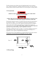
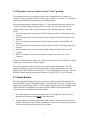
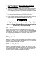
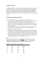
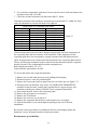
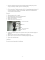
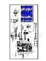
Model 30IM Service Manual Contents 1. Introduction Page 1.1 Product Specifications 2 1.2 Serial Nameplate 3 1.3 Before Servicing 3 1.4 After Servicing 4 1.5 Basic Refrigeration Tools 4 1.6 Installation 4 1.7 Electrical Requirements 5 1.8 Water Requirements 5 1.9 Gravity Drain 6 1.10 Drain Pump 7 1.11 Operation in ON position 7 1.12 Operation in CLEAN position 9 2. Sealed System 2.1 Introduction 9 2.2 Low Side Leaks 10 2.3 High Side Leaks 10 2.4 Restricted Capillary Tube 10 2.5 Access Valve 10 2.6 Pressures and Temperatures 11 2.7 Recharging 12 3. Sealed System Components 3.1 Hot Gas Valve 14 3.2 Evaporator 16 3.3 Compressor 19 3.4 Condenser 20 4. Valves 4.1 Drain Valve 21 4.2 Water Valve 22 5. System Components 5.1 Condenser Fan 23 5.2 Thermostats 24 5.3 Grid-cutter Transformer 27 6. Interior Components 6.1 Grid-cutter 28 6.2 Reservoir 29 6.3 Circulation Pump 30 7. Wiring 7.1 Wiring Diagram 31 7.2 Point-to-Point Wire Layout 32 8. Ordering Parts 35 9. Service Parts 36 10. Troubleshooting 43 11. Appendix A. Owner’s Guide B. Drain Pump Installation Instructions -1- 1.1 Specifications Cabinet dimensions: Height: 34 to 35 ¼ inches, adjustable Width: 14 ¾ inches Depth: 21 inches (cabinet only) 23 ½ inches (cabinet and door) Weight: 95 lbs. Shipping weight: 100 lbs. (approximate for standard models) Average ice making capacity per 24 hours: At 50F water temperature: 70F ambient: 35 lb/day 80F ambient: 30 lb/day 90F ambient: 23 lb/day At 70F water temperature: 70F ambient: 32 lb/day 80F ambient: 27 lb/day 90F ambient: 20 lb/day Electrical requirements: 115 VAC/60 Hz. Power cord length: 7 feet Compressor: Piston type Refrigerant charge: 5.0 oz. of R-134A Equalized pressure: 72 psi at 77F System refrigerant control: Capillary tube Temperature control: Electronic control with thermistor input Condenser fan motor: 2.3 W, 1300 RPM Water and drain controls: Solenoid activated. Flow controlled. -2- 1.2 Serial Nameplate The serial nameplate is located on the bottom flange directly above the grille on all Marvel units. Figure 1.1 gives the information that is provided. The serial number will need to be given whenever parts are ordered or when inquiring about the ice maker. Figure 1.1 1.3 Before Servicing h Power to the ice maker must be off before any attempt to service. This can be done by unplugging the unit or disrupting power to the ice maker receptacle. Verify power is disconnected to unit. h If unit has been running, use caution around condenser and copper tubing. These areas may be very hot. h Use caution around condenser fins and baseplate edges. These areas can be sharp. h Refrigerant is under high pressure. Evacuate system before attempting to open refrigerant system. h Reasonable care and safe work methods should be practiced when working on the ice maker. Do not work with energized electrical equipment in wet or damp areas. h Use an appropriate work area and location when performing repairs. You will find that it is easier to perform work on the ice maker if set on a raised platform or work table. h Wear protective safety glasses when performing any kind of work. h Any refrigerant, whether CFC, HCFC, or HFC (R-12, R-22, or R-134A) must be recovered. Federal regulations prohibit the intentional venting or release of refrigerants during the service repair or disposal of an appliance. -3- 1.4 After Servicing After servicing the unit, whether it is at the site or at service center, check the following: h MAKE CERTAIN THERE ARE NO LEAKS IN THE DRAIN OR WATER LINES. Check the water line, water valve, drain valve, and drain tubing for leaks. h Make certain the ice maker functions properly by observing ice production and ice harvest cycles. Check for hollow ice slabs or ice slabs that will not release. h Make certain the bin thermostat will turn the unit off. The best way to check this is to let the ice maker bin fill with ice. If time is restricted, however, use several ice cubes and place them on the bin thermostat’s capillary tube sleeve located on the side of the ice bin. The unit should shut down within a few minutes. After removing the ice, the unit should start at least five minutes later. 1.5 Basic Refrigeration Tools Here is a list of some of the basic tools needed: 1. 2. 3. 4. 5. 6. 7. 8. 9. 10. 11. 12. Hoses with R-134A couplers. Must meet standards for handling R-134A refrigerant Approved and certified recovery system for R-134A Manifold gage set for R-134A Charging cylinder with R-134A Weight scale, preferably in ounces to the nearest tenth of an ounce Access valves Tubing cutter both small and large Brazing torch Swaging tools Multimeter Leak detection equipment for detection of R-134A Standard hand tools. (Assorted phillips and standard screwdrivers, sockets, allen wrenches, adjustable wrenches, etc.) 13. Rivet gun and assorted rivets 14. Drill motor and assorted metal drills 1.6 Installation Location: h Unit can be installed freestanding or enclosed. The front of the unit must be unobstructed for proper air circulation and operation at all times. -4- h Area should be ventilated with temperature above 55F and below 90F for proper operation. h Unit must be installed indoors away from the elements of nature. h Unit must be on a level surface capable of supporting the loaded weight of the unit. h Refer to Appendix A, owner’s guide, for additional information. 1.7 Electrical Requirements Electrical Shock Hazard Failure to follow these requirements could result in personal injury, electrical shock, or fire. h 115 VAC, 60 Hz., single-phase power is needed. h Use outlet with a 15 amp. delayed action fuse or circuit breaker. Do not put a fuse on the neutral or ground of the circuit. h Properly grounded outlet is required for this unit. h It is recommended that a single circuit receptacle be used for this unit only. Do not use an extension cord. 1.8 Water Requirements h Use supplied water line fitting for water connection to the rear of the unit. h Use cold, potable water supply only with pressure between 20 to120 psi. h Use ¼ inch OD copper tubing. Plastic tubing can be used, but may leak with age. h Use ¼ inch saddle shut-off valve. Check to make sure valve complies with local codes. Do not use self-piercing saddle valve or less than ¼ inch saddle valve as water flow will be restricted. h A quality system water filter or local water filter is recommended. A quality filter can remove particles as well as remove unpleasant taste and odors from water. h Softened water is not recommended. Depending on mineral concentrations, this can produce mushy white cubes that may stick together. -5- The above materials can be found at most local plumbing supply stores or hardware stores. Follow the manufacture’s installation instructions for water valves and water line hook-ups. Make certain the waterline and the valve do not leak prior to enclosing cabinet. 1.9 Gravity Drain OBSERVE AND FOLLOW ALL LOCAL AND STATE CODES WHEN INSTALLING ICE MAKER. A DRAIN TRAP MUST BE USED FOR ICE MAKER DRAIN. FAILURE TO DO SO CAN RESULT IN EXPLOSION, PERSONAL INJURY, OR DEATH. The drain tube from the ice maker is 5/8 inch ID. This can be routed to a gravity drain in the area shown in figure 1.2 or to a remote gravity drain that is located below the ice maker. Be sure to check your local codes. Slope any long horizontal runs according to code to remote gravity drain for proper drainage. An air gap may be necessary for horizontal runs over 4 feet. Proper routing, sloping, and size of drain line is important especially if using flexible tubing, or poor ice production will result. If installing a standoff gravity drain, use Figure 1.2 for location. Standpipe can be up to 3 inches high above the floor. Route tubing from ice maker into the drain pipe. See Appendix A, owner’s guide, for additional drain information. It may be necessary in some installations to wrap drain tubing with wrap-type insulation. Condensation can form on the drain tubing and cause water damage. Figure 1.2 1.10 Drain Pump -6- 42242436, Marvel Drain Pump can be used to drain water when gravity drain is not available. Refer to Appendix B for drain pump installation instructions (also supplied with drain pump). As with the gravity drain, it may be necessary to wrap the drain tubing from the ice maker to the inlet of the drain pump with wrap-type insulation. Condensation can form on the drain tubing and cause water damage. 1.11 Operation. Selector switch is in the “ON” position. The assumptions before proceeding are that water is supplied to the ice maker (see section 1.8), there is proper electrical power to the ice maker (see section 1.7), and the drain is properly plumbed or the drain pump is operating properly. Input power must be applied at all times for proper operation. Any interrupt will lockout the compressor for up to 9 minutes and restart the mode of operation. Figure 1.3 below is the timing diagram/operation for the electronic control. * Figure 1.3 -7- Upon setting the switch to the “ON” position, the water solenoid will energize for 1.5 minutes and then de-energize. When the bin thermistor senses temperature at or above the “start ice” setpoint, and the evaporator thermistor senses temperature at or above the “production” setpoint, the production cycle will begin. The circulation pump, condenser fan, and compressor relay will energize. When the evaporator thermistor senses temperature at or below the “harvest” setpoint, the harvest cycle will begin. The circulation pump and condenser fan outputs will be de-energized and the hot gas solenoid and the drain solenoid will energize. The drain solenoid will remain energized for 45 seconds and then de-energize, after which the water solenoid will energize for 2.0 minutes and then de-energize. Loads will remain in this state until the evaporator thermistor temperature rises to the “production” setpoint. Once the evaporator thermistor temperature is at or above the “production” setpoint, a new production cycle will begin. If at any time the bin thermistor senses a temperature at or below the “stop ice” setpoint, any production or harvest cycle in process will continue until the harvest cycle is complete. Once complete, all loads will de-energize and remain so until the bin thermistor senses a temperature at or above the “start production” setpoint. A new production cycle will then begin. During the first production cycle only (the switch was previously in the “OFF” or “CLEAN” position), the evaporator thermistor temperature will be ignored until the circulation pump has run for 2 minutes. During all harvest cycles, the evaporator thermistor temperature cannot terminate the harvest cycle until the water solenoid is de-energized. The grid cutter output will always be energized during the harvest cycle, and for the first 35 minutes into the production cycle. If during any production cycle or harvest cycle, the selector switch is put into the “CLEAN” position, any cycle in process will be immediately terminated and a clean cycle will occur. The unit will now repeat the entire above cycle. If during any production or harvest cycle, the selector switch is put into the “OFF” position, the cycle in process will be stopped and all loads will de-energize and remain so as long as the selector switch remains in the “OFF” position. If during any production or harvest cycle, the selector switch is taken out of the “ON” position, a lockout will be started during which the compressor relay will not re-energize regardless of switch position. If during any production or harvest cycle, there is a power loss/interruption of greater than 25 milliseconds, a lockout delay will begin and the compressor relay will not reenergize upon re-application of power until the lockout delay is complete. The lockout delay begins with the loss of power and is unaffected by duration of power loss. All other loads will operate normally during the lockout. The setpoints are as follows: Stop ice: 35.0 deg. F +/- 2 deg. F Start ice: 43.0 deg. F +/- 2 deg. F Harvest: 11.0 deg. F +/- 2 deg. F Production: 45.0 deg. F +/- 2 deg. F Setpoint vs Temperarure and voltage (120VAC): +/- 3 deg. F -8- 1.12 Operation. Selector switch is in the “Clean” position. The assumptions before proceeding are that water is supplied to the ice maker (see section 1.8), there is proper electrical power to the ice maker (see section 1.7), and drain is properly plumbed or the drain pump is operating properly. Refer to timing/operation diagram in figure 1.3. Upon setting the selector switch to the “CLEAN” position during the production or harvest cycle, the water solenoid will energize and all other loads will be de-energized. The following sequence will now occur: 1. After 3.0 minutes the water solenoid will de-energize and the circulation pump will energize. 2. After 30 minutes the circulation pump will de-energize and the drain solenoid will energize. 3. After 75 seconds the drain solenoid will de-energize and the water solenoid will energize. 4. After 3.0 minutes the water solenoid will de-energize and the circulation pump will energize. 5. After 10 minutes the circulation pump will de-energize and the drain valve will energize. 6. After 75 seconds the drain solenoid will de-energize. The clean cycle is now complete. All loads will remain off as long as the selector switch remains in the “CLEAN” position and the power is not removed and re-applied. If at any time during a clean cycle the selector switch is moved from the “CLEAN” position, all loads except the drain solenoid will de-energize (this includes the “OFF” position). The drain solenoid will energize for 75 seconds and then de-energize. The unit will now operate normally according to whether it is in the “OFF” or “ON” position. 2.1 Sealed System The following should always be practiced with any sealed system that is opened. Only open the sealed system as the final diagnosis. Check all basic areas such as wiring, water supply, drain setup, proper air flow, etc first. Many times these areas can resemble sealed system problems. The diagnosis of a sealed system problem can be determined by accurate pressure and temperature measurements. 1. Use a leak detection system that will detect R-134A refrigerant. Leaks need to be found on any leaking system before repair takes place. 2. The drier must be replaced anytime the sealed system is opened. Order Marvel part number 42242961 for correct drier replacement. Failure to use correct part will result in repeated sealed system failure in the near future. -9- 3. Limit time the system is opened. DO NOT EXPOSE OPEN SYSTEM FOR MORE THAN 15 MINUTES. This will result in sealed system failure. Leave replacement parts sealed and/or pressurized until ready to install. 4. The compressor must be replaced if there is a low side leak. Moisture has been drawn into the system if the unit has been running for extended period of time. Be sure to flush the system with dry nitrogen gas and evacuate to 50 microns before re-charging (see section 2.3, Low Side Leaks). 5. A new evaporator assembly must be ordered (42242978) if the capillary tube is found to be plugged or severely restricted. Restrictions cannot be flushed out. 6. Be sure to purge the system after final brazing. This will flush out any air or moisture that may have entered the system before being absorbed into the ester oil. Testing of the electrical system, defrost system, controls, and air flow should be performed before entering any sealed system. What may first appear to be a system component failure may be only a simple control, air flow, electrical, or defrost system problem. 2.2 Low Side Leaks Low side leaks consist of a break in the system at the evaporator, low side (suction) return line, or accumulator. If a leak is found in any of these areas, moisture has probably entered the system. The compressor, drier, and hot gas valve will have to be replaced and the system will need to be flushed thoroughly with nitrogen gas and evacuated to 50 microns before recharging. 2.3 High Side Leaks High side leaks consist of a break in the system at the condenser, high side tubing, drier, or capillary tube. If a leak is found in any of these areas, the system can be flushed with nitrogen gas, evacuated to 50 microns, and recharged. 2.4 Restricted Capillary Tube Moisture or other contaminants that enter the system can cause deposits in the system. These deposits will usually collect in the capillary tube and form a restriction that cannot be completely removed by flushing. If the capillary tube is found to be restricted, the evaporator, compressor, condenser and drier should all be replaced. - 10 - 2.5 Access Valves A temporary access valve can be used to service or evaluate the system. The access valve can be installed on the compressor’s process tube (this will also be a low-pressure side). Be sure to cap off access valve while servicing. This will prevent contamination of the system and/or refrigerant from leaking. After servicing, the access valve should be removed. A pinch-off tool can be used to close the system to remove the access valve and then braze the hole for the access valve to seal the system. Be sure to leak check after brazing. 2.6 Pressures and Temperatures There are three ways to measure the temperature of the evaporator plate. 1. Use a thermocouple to measure the temperature of the evaporator. The thermocouple must be secured to the evaporator. The best and accurate location for the thermocouple end is where the thermistor is secured to the evaporator. Allow anywhere from 5-8F of variation in measured temperatures if you measure on the plate because of the thermal conductivity of stainless steel thermistor in comparison to the thermocouple. 2. If it has been determined that there is proper contact between the thermistor and the evaporator plate, the thermistor resistance value can be corresponded to the temperature (see section 5.2 for values). 3. If it has been determined that there is proper contact between the thermistor and the evaporator plate, the voltage at the thermistor terminals can be read. The voltage can be read while the unit is running by attaching test leads to thermistor terminals at the electronic control. The temperature to switch into the harvest cycle is 11.0 deg. F and the corresponding voltage is 3.0-3.1 V. The temperature to switch into the production cycle is 45 deg. F and the corresponding voltage is 1.9-2.0 V. Slight variations in actual measurements can occur due to input voltage variations. Note: The temperature and pressure readings must be taken with unit on and water flowing over the evaporator plate (in the production cycle). Use gage pressure readings from the compressor’s process tube (low side) access valve. Refrigeration Temperature-Pressure Chart for R-134A Degree F Pressure (psi) R-134A Degree F Pressure (psi) R-134A -12 1.1 36 31.3 -8 2.8 38 33.2 -4 4.5 40 35.1 0 6.5 42 37 2 7.5 44 39.1 4 8.5 46 41.1 6 9.6 48 43.3 8 10.8 50 45.5 10 12 52 47.7 - 11 - 12 14 16 18 20 22 24 26 28 30 32 34 13.1 14.4 15.7 17 18.4 19.9 21.4 22.9 24.5 26.1 27.8 29.5 56 60 64 68 72 76 80 84 88 92 96 100 52.3 57.5 62.7 68.3 74.2 80.3 86.8 93.6 100.7 108.2 116.1 124.3 Table A During production cycle, low side pressures will vary from 125 psi to 3 psi, depending at what point measurements are taken. High side pressures can range from 425 psi to 25 psi also depending at what point measurements are taken. In evaluating this system, the best point to determine if pressures are correct is at the end of the production cycle. This is the point where there is a thick slab formed on the evaporator and the evaporator thermostat is near cut-out temperature. Using Table A, use temperature to convert to a corresponding pressure. If low side pressure is below pressure in Table A, check for the following: 1. A system leak 2. Capillary tube is restricted 3. Insufficient compressor If low side pressure is above pressure in Table A, check for the following: 1. Restricted air flow 2. Dirty condenser coil 3. Leaking or energized hot gas valve 4. Overcharged system 5. Low side leak 2.7 Recharging Recharging of the unit should be done only after diagnosing and repairing the system (see Sealed System introduction). Be sure to flush the system with dry nitrogen gas and evacuate to 50 microns before re-charging. The method for recharging the unit is by weight using vapor refrigerant. Using manifold gage setup, hook up charge hoses to the access valve on the compressor’s process tube. If any access valve was attached to the high side process tube, remove it and seal the tube by brazing before charging. Charge the unit to 5.0 oz (0.313 lbs.) of R134A. - 12 - After recharge, check pressures. Refer to Table A for corresponding temperatures and pressures. If pressures or temperatures are incorrect, check the sealed system, recover the charge, repair, evacuate, and then recharge. NOTE: It is not uncommon to have some condensation or a slight frost on the suction line. This may occur towards the end of the production cycle. Liquid refrigerant is not getting into the compressor if the unit was charged properly. It is important that the insulation remains on the suction line and the capillary tube together after any repair and that it is sealed at both ends. - 13 - 3.1 Hot Gas Valve The hot gas valve is used to bypass the capillary tube and send warm gas to the evaporator when opened during the harvest cycle. The valve is actuated by a solenoid that opens the valve when energized and closes when de-energized. The valve seats using gravity so the valve must remain vertical to fully close. A faulty hot gas valve will result in long ice production cycles and higher than normal low side pressures. The valve usually fails by being stuck in the open or closed position, or by not fully seating in the closed position causing the valve to leak-by. A contaminated system or damage to the valve body will cause any of these failures. Care in keeping the system clean, handling the valve, keeping the valve cool during brazing, and evacuation of the system before charging must be done to prevent damage and eventual failure of the valve. Figure 3.1 Figure 3.2 Brazed joint (evaporator bypass tube) Solenoid retainer Brazed joint (tee fitting) Drier assembly brazed joint Hot gas solenoid Hot gas valve A quick way to check the valve to see that it opens and closes freely (with the system still sealed) is to repeatedly energize and de-energize the solenoid and listen for the valve opening and closing. You should be able to hear a distinct “click” of the valve opening and closing. If you can not hear this, then the valve is stuck and will need to be replaced. The solenoid coil itself can be check by measuring resistance across the electrical terminals. A resistance reading of 380-390 ohms should be found in a good solenoid coil. Replacing the hot gas valve Removal: 1. Disconnect power, water line, and drain line. If a drain pump is used, it will need to be disconnected and removed. 2. Remove the access panel and rear panel (see figure 3.3). - 14 - 3. Remove the grille by removing the two screws and disconnecting the three wires to Rear panel Access panel Figure 3.3 the rocker switch. Be sure to mark where these wires go for re-assembly. 4. Remove the drain valve. 5. Remove the water valve. 6. Take out the two screws that secure the top of the electrical bracket located in the front of the mechanical area (see figure 3.4). 7. Remove the six screws that secure the baseplate to the cabinet on the bottom of the unit (see figure 3.5). Remove six screws on the bottom of the unit to slide out the mechanical. Figure 3.4 Remove these two screws for the electrical bracket to slide out the mechanical assembly. Figure 3.5 Figure 3.4 8. Gently slide the mechanical out the rear of the unit just enough to gain access to the hot gas valve and drier assembly (see figure 3.6). Figure 3.6 - 15 - 9. Install system access valve(s) and recover refrigerant. After recovering, be sure to cap off the access valve to prevent contamination of the system. 10. Disconnect the wires at the solenoid, remove the solenoid-retaining clip, and remove the solenoid (see figure 3.2). 11. Un-braze the brazed union upstream of the hot gas valve (see figure 3.2). Be sure to cap off after tubing has cooled. 12. Un-braze and remove the capillary tube from the drier assembly. 13. Un-braze the drier assembly at the end of the condenser (see figure 3.1). Be sure to cap off after cooling. Installation: 1. Bend hot gas valve tubing similar to one being replaced. Do not kink tubing or overstress tubing at valve joints. 2. Braze in new drier assembly and then the capillary tube. 3. Apply a heat sink or a damp cloth on the valve body to keep heat away. Failure to keep the valve body cool will result in a leaky valve. 4. Braze the hot gas valve tube (from the side of the valve) into the tee on the drier assembly. 5. Braze the hot gas valve tube (from the bottom of the valve) into the evaporator bypass tube. 6. Cool the brazed joints with damp cloth. 7. Remove the heat sink or damp cloth from the valve body. 8. Check for leaks using dry nitrogen gas and a leak detection system. 9. Flush the system and recharge. 10. Reassemble reversing steps 1 through 10. 3.2 Evaporator The evaporator uses evaporating refrigerant to remove heat from the water that flows over the evaporator plate to form an ice slab. The ice slab will simply slide down the evaporator plate onto the grid-cutter during harvest. The evaporator plate will over time have a build up of mineral deposits. The evaporator will not need to be replaced due to the mineral deposits. These deposits must be removed periodically for proper ice maker performance. The evaporator must also be free of nicks and scratches. A nice polished and smooth evaporator will allow the ice machine to perform correctly, giving the best performance by allowing the ice slab to slide freely and allowing the water to have proper evaporator to water contact. If nicks and scratches are found, replacement is not needed. Simply remove the nicks and scratches with fine sanding material and then use a polish for stainless steel. If the evaporator has a leak, it should be replaced. A leak detection device will confirm a leaking evaporator assembly. Remember, if a leak in the evaporator, accumulator, or - 16 - low side tubing is found, the compressor, drier, and hot gas valve will need to be replaced. The temperature control thermistor sets on the bottom of the evaporator plate on a copper bracket. This bracket should be checked at the solder joint. Any cracks will break the proper thermal conductivity between the evaporator plate and the thermistor and result in long production cycle with a thick slab on the plate. The thermistor should also be secured tight and have full contact to the copper bracket or thermal conductivity again will be sacrificed. Replacing the evaporator: 1. Disconnect power, water line, and drain line. If a drain pump is used, it will need to be disconnected and removed. 2. Remove the door from the front of the unit. 3. Remove the escutcheon panel. 4. Remove the grid-cutter (see section 6.1). 5. Remove the ice deflector. 6. Remove the reservoir (see section 6.2). 7. Remove the circulation pump (see section 6.3), hose, and distributor. 8. Remove the stainless steel evaporator thermistor fastened on the bottom of the evaporator with a stainless hex head or phillips screw. 9. Remove the four screws securing the evaporator plate. 10. Remove the access panel and rear panel at the rear of the unit (see figure 3.3). 11. Remove the bin sensing tube with the bin thermistor remaining inside it. It is not necessary to remove the bin thermistor from the sleeve. Remove through the opening in the rear of the liner. 12. Remove the putty and the water line from the opening in the rear of the liner. 13. Remove the grille by removing the two screws and disconnecting the three wires to the rocker switch. Be sure to mark where these wires go for re-assembly. 14. Remove the drain valve. 15. Remove the water valve. 16. Take out the two screws that secure the top of the electrical bracket located in the front of the mechanical area (see figure 3.4). 17. Remove the six screws that secure the baseplate to the cabinet on the bottom of the unit (see figure 3.5). 18. Gently slide the mechanical out the rear of the unit just enough to gain access to the assembly (see figure 3.6). 19. Install the access valve and recover refrigerant. After recovering, be sure to cap off the access valve to prevent contamination of the system. 20. Remove the cap from the rear of the compressor. 21. Disconnect the PTC starter relay at the compressor by pulling off. You will not need to disconnect the three wires. 22. Un-braze and remove the capillary tube from the drier assembly. 23. Un-braze the hot gas valve tube at the evaporator bypass tube (see figure 3.2). 24. Un-braze and remove the drier assembly at the condenser (see figure 3.1). - 17 - 25. Un-braze and remove the suction line at the compressor (see figure 3.8). 26. Un-braze the hot gas discharge line at the compressor (see figure 3.8). Hot gas discharge line Process tube Compressor lock-nut Drier assembly Figure 3.8 Process tube (high side) 27. Remove the compressor by removing the two lock-nuts on the mounting plate of the compressor. Lift the compressor off of the carriage bolts (see figure 3.8). 28. Install the four rubber grommets in the bottom of the new compressor and install the two sleeves where the carriage bolts will be located. Mount the new compressor and install the two washers and lock-nuts and tighten to 45 in-lb. DO NOT REMOVE THE RUBBER PLUGS AT THE TUBE STUBS ON THE COMPRESSOR AT THIS TIME. 29. Remove the insulation tube on the evaporator tubing harness. 30. Remove the evaporator from the front of the unit. The evaporator will need to be tilted 90 degrees down and the tubing harness with the accumulator will fit through the opening in the liner. Installation: Reverse the removal instructions for installation. Remove the plugs from the compressor right before brazing. Make certain that the suction line and tubing harness insulation tube are installed and sealed. Also, check the thermistor to make sure it has full contact and is secure. Be sure to check for leaks, flush the system thoroughly and evacuate to 50 microns. Weight charge the system (see section 2.7). - 18 - 3.3 Compressor The compressor is the heart of the refrigeration system. It also, however, relies on other parts of the system to function. Make certain that the other parts of the system are correctly functioning before determining that the compressor is faulty. The compressor is protected from power interruptions with a start delay built into the control to prevent high pressure startup (see section 1.11 Operation). DO NOT mistake this for a faulty compressor. The following must also be observed before concluding the compressor is faulty: 1. Low high side pressures, warm evaporator plate, cool condenser coil, or little or very low current draw from the unit will indicate a faulty compressor. 2. Check for continuity between the compressor terminals and the shell of the compressor. If continuity is found, the compressor is faulty and will need replaced. 3. Check for resistance between all three compressor terminals. The resistance will vary from terminal to terminal and from compressor to compressor due to age and use. If no resistance is found, the compressor is faulty and will need replaced. Removal 1. Disconnect power, waterline, and drain line. If a drain pump is used, it will need to be disconnected and removed. 2. Remove the access panel and rear panel at the rear of the unit (see figure 3.3). 3. Remove the grille by removing the two screws and disconnecting the three wires to the rocker switch. Be sure to mark where these wires go for re-assembly. 4. Remove the drain valve. 5. Remove the water valve. 6. Take out the two screws that secure the top of the electrical bracket located in the front of the mechanical area (see figure 3.4). 7. Remove the six screws that secure the baseplate to the cabinet on the bottom of the unit (see figure 3.5). 8. Gently slide the mechanical out the rear of the unit just enough to gain access to the drier assembly (see figure 3.6). 9. Install sealed system access valve(s) and recover refrigerant. After recovering, be sure to cap off the access valve to prevent contamination of the system. 10. Remove the cap from the rear of the compressor. 11. Disconnect the PTC starter relay at the compressor by pulling off. You will need to disconnect the three wires from the old PTC starter and then connect the new one. 12. Un-braze and remove the capillary tube from the drier assembly. 13. Un-braze the tube from the hot gas valve at the tee fitting on the drier assembly (see figure 3.1). 14. Un-braze and remove the drier assembly. 15. Un-braze and remove the suction line at the compressor (see figure 3.8). 16. Un-braze the hot gas discharge line at the compressor (see figure 3.8). - 19 - 17. Remove the compressor by removing the two lock-nuts on the mounting plate of the compressor (see figure 3.8). Lift the compressor off of the carriage bolts. Installation: 1. Install the four rubber grommets in the bottom of the new compressor and install the two sleeves where the carriage bolts will be located. Mount the new compressor and install the two washers and lock-nuts and tighten to 45 in-lb. DO NOT REMOVE THE RUBBER PLUGS AT THE TUBE STUBS ON THE COMPRESSOR AT THIS TIME. 2. Install and braze the new drier assembly to the condenser. Then install and braze the capillary tube and the hot gas valve tube. 3. Remove the plug for the hot gas line at the compressor. Install and braze the hot gas line to the compressor. 4. Remove the plug for the process tube on the compressor. Install and braze in the process tube. Be sure to cap off the end to prevent any contamination. 5. Remove the plug for the suction line on the compressor. Install and braze in the suction line from the evaporator. Be sure to also reinstall the suction line and tubing harness insulation tubes. 6. Reinstall PTC starter and wire according to wire diagram. 7. Reinstall compressor cap. 8. Reverse steps 1 through 8 of removal for remaining installation. 9. Refer to section 2.7 for recharging. 3.4 Condenser The condenser is a steel tube serpentine with copper alloy fins, which removes heat from hot, high pressure vapor from the compressor. The most common trouble is lack of air flow from either a restricted intake or exhaust opening in the front of the unit. Lint, dust, hair, and dirt build-up needs to be removed from the condenser periodically to allow the unit to perform properly. It is possible that the condenser might need replaced because of an un-repairable leak or a restriction that cannot be flushed out. System high side pressures and temperatures will verify if this is the case. Removal 1. Disconnect power, water line, and drain line. If a drain pump is used, it will need to be disconnected and removed. 2. Remove the access panel and rear panel (see figure 3.3). 3. Remove the grille by removing the two screws and disconnecting the three wires to the rocker switch. Be sure to mark where these wires go for re-assembly. 4. Remove the drain valve. - 20 - 5. Remove the water valve. 6. Take out the two screws that secure the top of the electrical bracket located in the front of the mechanical area (see figure 3.4). 7. Remove the six screws that secure the baseplate to the cabinet on the bottom of the unit (see figure 3.5). 8. Gently slide the mechanical out the rear of the unit enough to gain access to the condenser coil and fan shroud (see figure 3.6). 9. Install sealed system access valve(s) and recover refrigerant. After recovering, be sure to cap off the access valve to prevent contamination of the system. 10. Remove the fan by removing the two nuts on the fan mounting bracket at the baseplate. The fan wire leads can be left connected. Set the fan assembly to the side of the mechanical. 11. Remove the three nuts retaining the side of the fan shroud. Remove the fan shroud. 12. Un-braze the capillary tube from the drier assembly. 13. Un-braze the hot gas valve tube at the tee on the drier assembly (see figure 3.1). 14. Un-braze and remove the drier assembly. 15. Un-braze the hot gas line from the compressor at the top of the condenser coil (see figure 3.8). Installation Reverse the removal procedure. Be sure to thoroughly flush the system and evacuate to 50 microns before weight charging. If contamination was found or determined, the evaporator should also be replaced at this time. 4.1 Drain Valve The drain valve drains water that is left in the reservoir after ice production. The valve will only be open for a fixed time of 45 seconds during the beginning of the harvest cycle. The drain valve fails by allowing water to flow into the drain during the ice production cycle (leak-by). This is can be caused by a foreign particle(s) or build-up of mineral deposits that will not allow the valve to fully seat or has caused damage to the seat of the valve. Periodic cleaning of the ice maker will keep build-up off valve allowing it to work properly and should be done before further evaluation of the valve. Symptoms of this include thin or no ice slab (depending on severity of leak) and, more noticeably, water draining through to the drain during the ice production cycle (do not mistake this for reservoir run off water or melted ice drain water from the ice bin). The drain valve should be replaced if it is found to be leaking. The drain valve solenoid actuator can also possibly fail. Test the solenoid by checking the resistance. A resistance of 50-65 ohms should be found. If no resistance is found, the drain valve will need to be replaced. - 21 - Removal 1. Drain water in the reservoir by removing the drain plug or shutting off the water supply and allowing ice maker to cycle through ice harvest cycle. Replace the drain plug, if used, after the water has been drained. 2. Disconnect power, water line, and drain line. If a drain pump is used, it will need to be disconnected and removed. 3. Remove the access panel and rear panel (see figure 3.3). Hose 4. Remove the brown and white clamps wire terminals at the drain valve. 5. Loosen the hose clamps on each side of the drain valve (see figure 4.1). 6. Remove the two screws securing the drain valve (see figure 4.1). Figure 4.1 7. Remove the drain valve. Installation Reverse the removal procedure for installation. It is important to keep the valve clean during installation to assure proper performance. After installation, make certain the hose clamps are secure and that the valve or the tubing does not leak. This can be done by adding water to the reservoir and observing for any leaks from the tubing connections or the valve itself. 4.2 Water Valve The water valve supplies water to the reservoir for producing ice. The valve opens for 1.0 minutes during initial start-up of the unit and opens for 2.0 minutes in the harvest cycle after the drain valve has closed. The valve has a built-in screen in the water supply fitting. This screen will filter out any large particles and, over time, these particles will accumulate and restrict water supply. If this is found, simply clean the screen with a toothbrush to remove the particles. DO NOT REMOVE THE SCREEN FROM THE VALVE. To check the water valve: 1. Check the solenoid actuator for resistance. If no resistance is found, the valve will need to be replaced. 2. Check to see if the valve will seat properly. Foreign particles that may have passed the filter could damage the seat of the valve. To make sure the valve is seating, make sure power is disconnected to the unit, hook up the water supply, turn on the water - 22 - Screw Drain valve supply, and see if there is any water flowing in the water lines. If water is present and flowing, the valve will need to be replaced. 3. Check the flow rate of the reservoir water line. Using a stopwatch or a watch with a second hand, see what amount of time it takes to fill up a one quart container. The time should be 60 seconds to get the .25 gpm specifications of the valve. h If it takes substantially less than 60 seconds, check the water supply pressure to make certain it is not above 120 psi static pressure. If it is not, the metering orifice of the valve has been changed and the valve will need to be replaced. h If it takes substantially more than 60 seconds, check the water supply pressure to maker certain it is not below 20 psi static pressure. If it is not, make certain the valve screen filter is clean. If the filter is clean, replace the valve. Removal: 1. 2. 3. 4. Disconnect power, water line, and drain line. Remove the access panel and rear panel (see figure 3.3). Remove the blue and white wire terminals at the water valve. Loosen the reservoir water supply line compression nut from the bottom of the water valve. 5. Remove the two screws securing the water valve to the unit’s support pan. 6. Remove the water valve. Installation: Reverse the removal procedure for installation. Make certain that the reservoir waterline is in the reservoir inside the unit and there are no water leaks anywhere after installation. 5.1 Condenser Fan The condenser fan is used to force air over the condenser coil. The fan will run only during ice production cycle and turn off in ice harvest cycle. To check the condenser fan: h Make sure motor shaft turns freely. This can be done by rotating the fan blade by hand and observing any excessive resistance. h Check for resistance between terminals. If no resistance is found, replace the condenser fan. h Check for continuity between terminals and fan casing. If continuity is found, replace the condenser fan. h Check current draw. Typical current draw will be .15 amp without fan resistance. If current draw is .19 amp or more, check for resistance in air movement or objects touching the fan blade. If this is not found, then replace the condenser fan. - 23 - Removal 1. Disconnect power, water line, and drain line. If a drain pump is used, it will need to be disconnected and removed. 2. Remove the access panel and rear panel (see figure 3.3). 3. Remove the grille by removing the two screws and disconnecting the three wires to the rocker switch. Be sure to mark where these wires go for re-assembly. 4. Remove the drain valve. 5. Remove the water valve. 6. Take out the two screws that secure the top of the electrical bracket located in the front of the mechanical area (see figure 3.4). 7. Remove the six screws that secure the baseplate to the cabinet on the bottom of the unit (see figure 3.5). 8. Gently slide the mechanical out the rear of the unit enough to gain access to the condenser fan (see figure 3.6). 9. Remove the two nuts that secure the condenser fan. 10. Disconnect the neutral white wire lead (black ribbed wire) at the terminal block and the hot wire lead (black smooth wire) at the electronic control. 11. Remove the condenser fan. Installation Reverse the removal procedure for installation. 5.2 Thermistors This unit utilizes two thermistors for reading temperatures for input to the electronic control. Each thermistor has a different function for input to the electronic control. Evaporator thermistor ( p/n 41006205): The evaporator thermistor is made up of a stainless steel body and is secured to the under side of the evaporator. The location of the thermistor allows the thermistor to give voltage input to the electronic control. This input is processed through the electronic control to switch the ice maker into the production or the harvest cycles. The thermistor must be tightly secured to the evaporator bracket for proper heat transfer. The following will happen in the event of a thermistor failure: 1. If an evaporator thermistor fails, all loads will be shut off and the unit will not run. 2. If the evaporator thermistor senses temperature outside of 0-140 deg. F, all loads will be shut off and the unit will not run. The thermistor can be check by use of a multi-meter with the ability to read resistance. To check the thermistor: 1. Disconnect and remove the thermistor from the unit. - 24 - 2. Use a reference temperature point that is known (such as an ice bath) and measure the resistance across the wire leads. 3. Check the recorded resistance with that in the table 5.1 below. If measured resistance falls outside the resistance given in the table 5.1 within 4% of the value, the thermistor is bad and will need to be replaced. RESISTANCE VS. TEMPERATURE CHART TEMPERATURE (C) TEMPERATURE (F) RESISTANCE (KOHMS) -15 5 11.350 -10 14 8.918 -5 23 6.700 0 32 5.630 5 41 4.520 10 50 3.652 15 59 2.970 20 68 2.430 25 77 2.000 Table 5.1 If the thermistor has been tested and is found to be good then check the temperature of the evaporator plate and the resistance of the thermistor. If the temperature of the evaporator plate does not correspond to a proper resistance from the thermistor then check for proper and secure connection of the thermistor to the evaporator plate bracket. The use of a heat sink compound can be used between the thermistor and the evaporator bracket if needed. The recommended heat sink compounds are: Radio Shack part number 276-1372 General Electric part number 10-8108 To access and replace the evaporator thermistor: 1. 2. 3. 4. Remove any ice and drain the reservoir by pulling the drain plug. Disconnect power, water line, and drain line. Remove the access panel and rear panel from the rear of the unit (see figure 3.3). Disconnect the red and black wires to the “EVAPORATOR THERMISTOR” terminals on the electronic control (there should also be a tag on the gray wire insulation with the part number 41006205 for the evaporator thermistor). 11. From inside the unit, remove the escutcheon panel. 12. Remove the grid-cutter (see section 6.1). 13. Remove the ice deflector. 14. Remove the reservoir (see section 6.2). 15. Remove the evaporator thermistor by removing the screw securing it. 16. Feed the thermistor’s wire out through the opening in the rear of the unit. Installation: Reverse the removal procedure for installation. Be sure to thoroughly tighten the thermistor’s screw for proper bracket to thermistor contact. Bin thermistor (p/n 41006204): - 25 - The bin thermistor is made up of a soft copper tube body and placed inside a plated copper sensing tube. This plated tube is then secured to the side of the ice maker’s bin to detect the ice bin level. The bin thermistor gives voltage input to the electronic control. This input is processed through the electronic control to switch the ice maker into stop making ice or start making ice. The thermistor must be fully inserted into the plated sensing tube for proper detection. Once the bin thermistor detects to stop making ice, the electronic control will continue in ice production or harvest until a harvest cycle is complete. See section 1.11. The following will happen in the event of a thermistor failure: 1. If a bin thermistor fails, all loads will be shut off and the unit will not run. 2. If the bin thermistor senses temperature outside of 25-140 deg. F, all loads will be shut off and the unit will not run. The thermistor can be checked by use of a multi-meter with the ability to read resistance. To check the thermistor: 1. Disconnect and remove the thermistor and sensing tube from the unit. 2. Use a reference temperature point that is known (such as an ice bath) and measure the resistance across the wire leads. 3. Check the recorded resistance with that in the table 5.1. If measured resistance falls outside the resistance given in the table 5.1 within 4% of the value, the thermistor is bad and will need to be replaced. Bin thermistor and sleeve removal: 1. 2. 3. 4. Remove any ice and drain the reservoir by pulling the drain plug. Disconnect power, water line, and drain line. Remove the access panel and rear panel from the rear of the unit (see figure 3.3). Disconnect the red and black wires to the “BIN THERMISTOR” terminals on the electronic control (there should also be a tag on the gray wire insulation with the part number 41006204 for the bin thermistor). 5. From inside the unit, remove the escutcheon panel. 6. Remove the grid-cutter (see section 6.1). 7. Remove the ice deflector. 8. Remove the reservoir (see section 6.2). 9. Remove the bin thermistor and sleeve assembly by removing the screws securing it to the ice maker’s bin. 10. Feed the thermistor’s wire out through the opening in the rear of the unit. 11. Remove the sensing tube from the unit out the opening in the rear. 12. The bin thermistor will slide out of the sleeve. - 26 - Installation: Reverse the removal procedure for installation. Make certain that the thermistor’s copper tube is fully inserted into the sleeve. 5.3 Grid-Cutter Transformer The grid-cutter transformer is used to step down the voltage to the grid-cutter to 12 VAC. The transformer is on only from the start of a harvest cycle to 35 minutes from the start of the production cycle. The transformer itself can be checked by applying 120VAC to the marked 120V (for the hot lead) and COM (neutral lead) side of the transformer and reading the 12V side using a multimeter. If no readout is found or readout is below 10VAC, replace the transformer. Removal: 1. Disconnect power, water line, and drain line. If a drain pump is used, it will need to be disconnected and removed. 2. Remove the access panel and rear panel (see figure 3.3). 3. Remove the grille by removing the two screws and disconnecting the three wires to the rocker switch. Be sure to mark where these wires go for re-assembly. 4. Remove the drain valve. 5. Disconnect the hot gas valve solenoid orange and white wires at the solenoid. 6. Remove the hot gas valve solenoid coil by removing the spring retainer, rotating the coil 90 degrees, and then lifting up. 7. Take out the two screws that secure the top of the electrical bracket located in the front of the unit (see figure 3.4). 8. Remove the three nuts and carriage bolts that secure the bottom of the electrical bracket and secure the power cord clamp. 9. Gently slide the electrical bracket assembly to the rear of the unit. The condenser fan wire leads may need to be disconnected if the bracket does not slide all the way to the rear of the unit. 10. Mark and remove the four wires to the transformer. 11. Remove the two screws that secure the transformer. 12. Remove the transformer. Installation: Reverse the removal procedure for installation. Make certain all wire connections are secure and the power cord’s ring terminal ground is secured. The spring retainer on the hot gas valve must be secured and seated properly. - 27 - 6.1 Grid-Cutter The grid-cutter is used to cut cubes from the ice slab formed on the evaporator. It uses low voltage, 12VAC, to heat the wires. Wires are warm to the touch of a hand when not under the load of a slab of ice. The grid-cutter is on only from the start of a harvest cycle to 35 minutes from the start of the production cycle (see section 1.11). There is no repair for the grid-cutter. It will have to be replaced as an assembly. To test the grid-cutter: h Check the resistance at the outside grid-cutter’s plug-in terminals (note: the middle terminal is not used). If the resistance between the terminal of the plug is 5.0-5.9 ohms, the grid-cutter is good. At any other resistance readings, it will need to be replaced. h Check for continuity between terminals and the grid-cutter’s stainless steel frame. If continuity is found, check for wires that are not on the insulators. Removal: 1. From inside the unit, remove the escutcheon panel. Grid-cutter receptacle Make certain that wires are away from the path of the ice slab. Screws Escutcheon panel brackets Grid-cutter assembly Figure 6.1 2. Unplug the grid-cutter from the receptacle on the side of the liner (see figure 6.1). 3. Remove the four screws that secure the grid-cutter and escutcheon panel brackets (see figure 6.1). 4. Slide the escutcheon panel brackets out. 5. Remove the grid-cutter. Installation: 1. Re-install the grid-cutter and escutcheon panel brackets with the four screws. - 28 - 2. Plug the grid-cutter into the receptacle on the side of the liner. Route the plug wire between the reservoir and liner (see figure 6.1). This will keep it away from the path of the ice slab. 3. Re-install the escutcheon panel. Adjustment to the brackets may be necessary to align the escutcheon panel. 6.2 Reservoir The reservoir retains the water needed to produce an ice slab. It will hold a maximum of 3 quarts of water. Anything over 3 quarts will be drained in the reservoir’s overflow. Anytime the reservoir is removed, it should be cleaned with ice machine cleaner. Be sure to rinse the reservoir before re-installing. To remove the reservoir: 1. 2. 3. 4. 5. 6. 7. From inside the unit, remove the escutcheon panel. Remove the grid-cutter (see section 6.1). Remove the four screws that secure the ice deflector. Remove the ice deflector. Drain the reservoir by removing the drain plug located on the bottom of the reservoir. Remove the two screws and spacers that secure the reservoir (see figure 6.2). Remove the reservoir by lifting the drain tube off the reservoir and away from the circulation pump (see figures 6.3 and 6.4). Remove the two screws and spacers at the reservoir Reservoir Figure 6.2 Gently lift reservoir off drain tube (figure 6.3), then lower the reservoir to clear the circulation pump (figure 6.4) Figure 6.4 Figure 6.3 - 29 - Installation 1. Slide the circulation pump into the reservoir. 2. Insert the reservoir drain tube fitting to the drain tube in the rear of the liner. 3. Tilt the reservoir forward and line up the screw holes in the reservoir with those of the liner. 4. Insert the spacer to the outside of the reservoir and then the screw and plastic washer to the inside of the reservoir. Repeat for the other side. Water line is away from the path of the ice slab. Figure 6.5 5. Route the water line from the circulation pump between the liner and the reservoir. This will keep it away from the path of the ice slab (see figure 6.5). 6. Re-install the ice deflector. 7. Re-install the grid-cutter and escutcheon panel brackets. 8. Plug the grid-cutter into the receptacle on the side of the liner. Route the plug wire between the reservoir and liner. This will keep it away from the path of the ice slab. 9. Re-install the escutcheon panel. Adjustment to the brackets may be necessary to align the escutcheon panel. 6.3 Circulation Pump The circulation pump is used to circulate the water in the reservoir over the evaporator. The circulation pump will run only during ice production cycle and turn off in ice harvest cycle. The pump is a centrifugal impeller type pump. The pump and motor are an assembly that cannot be repaired separately. To check the circulation pump (with the pump removed): h Make sure motor shaft turns freely. This can be done by rotating the pump’s drive shaft and observing any excessive resistance. h Check for resistance between terminals. If no resistance is found, replace the circulation pump. - 30 - h Check for continuity between the hot and neutral terminals and the pump’s motor casing. If continuity is found, replace the circulation pump. h Check current draw. Typical current draw will be .36 amp without pump resistance. If excessive current draw is found, check the pump’s impeller for foreign particles or severe build-up of mineral deposits. Removal 1. 2. 3. 4. 5. Disconnect power to the ice maker. From inside the unit, remove the escutcheon panel. Remove the grid-cutter (see section 6.1). Remove the ice deflector. Remove the reservoir (see section 6.2). Circulation pump plug Screws Circulation pump Water line Figure 6.6 6. Unplug the circulation pump at the receptacle at the top of the circulation pump (see figure 6.6). 7. Disconnect the water line at the circulation pump (see figure 6.6). 8. Remove the two screws that secure the circulation pump (see figure 6.6). 9. Remove the circulation pump. Installation Reverse the removal procedure for installation. - 31 - Figure 7.1 7.1 Wiring Diagram Figure 7.1 is the wiring diagram for the ice maker. 7.2 Point-to-Point Wire Layout The diagram on the following page, figure 7.2, shows point-to-point termination. This diagram is also located on the back panel of the unit along with the wiring diagram (figure 7.1). - 32 - Figure 7.2 - 33 - Notes: - 34 - 8 Ordering Parts The following information will need to be given when inquiring about service parts: 1. 2. 3. 4. Model and serial number located on the serial nameplate (see section 1.2) The color of the model Metal or plastic grille Type of door (replacement panel or standard) To order, call or write: Marvel Industries Customer Service P.O. Box 997 Richmond, IN 47375 Phone: (800) 428-6644 or (765) 962-2521 Fax: (765) 962-2493 - 35 -