
1
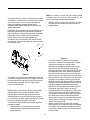
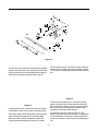
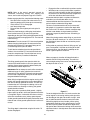
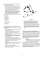
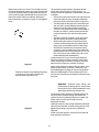
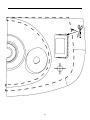
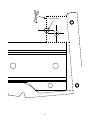
Operator’s Manual
Model 190-002
30” Hydraulic
Tiller Attachment
REQUIRED FOR USE:
Weight Kit Bracket
(190-307-100)
Suitcase Weights (3 Req’d)
(190-390-100)
IMPORTANT: Read safety rules and instructions carefully before operating equipment.
CUB CADET CORP. P.O. BOX 368023 CLEVELAND, OHIO 44136-9722
PRINTED IN U.S.A.
TABLE OF CONTENTS
Content
Page
Important Safe Operation Practices................................................................... 3
Slope Gauge ..................................................................................................... 6
To the Owner .................................................................................................... 7
Loose Parts........................................................................................................ 7
Assembling the Tiller.......................................................................................... 7
Preparing the Tractor ........................................................................................ 9
Mounting the Tiller ............................................................................................ 12
Know the Tiller ................................................................................................... 14
Operating the Tiller ............................................................................................ 15
Maintenance ...................................................................................................... 18
Storage .............................................................................................................. 21
Troubleshooting ................................................................................................. 22
Templates .......................................................................................................... 23
FINDING MODEL NUMBER
This Operator’s Manual is an important part of your new tiller attachment. It will help you assemble, prepare
and maintain the unit for best performance. Please read and understand what it says.
Before you start assembling your new equipment, please locate the model plate on the
equipment and copy the information from it in the space provided below. The information on
the model plate is very important if you need help from your local authorized Cub Cadet
dealer.
You can locate the model number by looking at the left side of the tiller frame near the top. A sample model
plate is explained below.
(Model Number)
(Serial Number)
Copy the model number here:
CUB CADET CORP.
Copy the serial number here:
P.O. BOX 368023
CLEVELAND, OHIO 44136
CALLING WARRANTY SERVICE
If you have difficulty assembling this product or have any questions regarding the controls, operation or
maintenance of this unit, please call the Customer Dealer Referral Line.
Call 1-(800)-528-1009 to locate your nearest Cub Cadet dealer. Before contacting your local
dealer, be sure to have your unit’s model number and serial number ready. See previous
section to locate this information.
2
SECTION 1: IMPORTANT SAFE OPERATION PRACTICES
WARNING: This symbol points out important safety instructions which, if not followed, could endanger
the personal safety and/or property of yourself and others. Read and follow all instructions in this
manual before attempting to operate this machine. Failure to comply with these instructions may result
in personal injury. When you see this symbol—heed its warning.
DANGER: This machine was built to be operated according to the rules for safe operation in this
manual. As with any type of power equipment, carelessness or error on the part of the operator can
result in serious injury. This machine is capable of amputating hands and feet, and throwing objects.
Failure to observe the following safety instructions could result in serious injury or death.
General Operation
•
•
•
•
•
•
•
Read this operator’s manual carefully in its entirety
before attempting to assemble this machine. Read,
understand, and follow all instructions on the
machine and in the manual(s) before operation. Be
completely familiar with the controls and the proper
use of this machine before operating it. Keep this
manual in a safe place for future and regular
reference and for ordering replacement parts.
This machine is a precision piece of power
equipment, not a plaything. Therefore, exercise
extreme caution at all times. Your unit has been
designed to perform one job: to till soil. Do not use it
for any other purpose.
Never allow children under 14 years old to operate
this machine. Children 14 years old and over should
read and understand the operation instructions and
safety rules in this manual and should be trained
and supervised by a parent. Only responsible
individuals who are familiar with these rules of safe
operation should be allowed to use your machine.
Thoroughly inspect the area where the equipment is
to be used. Remove all stones, sticks, wire, bones,
toys and other foreign objects which could be
picked up and thrown by the tiller tines in any
direction which could cause serious personal injury
to the operator or any others allowed in the area.
Plan your tilling pattern to avoid discharge of
material toward roads, sidewalks, bystanders and
the like. To help avoid tine contact or a thrown
object injury, keep children, bystanders and helpers
at least 75 feet from the tiller attachment while it is in
operation. Stop tiller if anyone enters the area.
Always wear safety glasses or safety goggles
during operation or while performing an adjustment
or repair to protect eyes from foreign objects that
may be thrown from the machine in any direction.
Wear sturdy, rough-soled work shoes and closefitting slacks and shirts. Shirts and pants that cover
the arms and legs and steel-toed shoes are
recommended. Loose fitting clothes and jewelry
can be caught in movable parts. Never operate a
unit in bare feet, sandals, slippery or light weight
(e.g. canvas) shoes.
•
•
•
•
•
•
•
•
•
•
•
•
•
•
3
Do not put hands or feet near or under rotating
parts. Keep clear of the tiller tines at all times as the
rotating tines can cause injury.
Never operate the tiller without the rear deflector in
its proper place.
Disengage the PTO and raise the tiller attachment
when crossing gravel drives, walks, or roads.
Watch for traffic when operating near or crossing
roadways. This machine is not intended for use on
any public roadway.
Do not operate while under the influence of alcohol
or drugs.
Use tiller attachment in daylight or in good artificial
light only.
Never carry passengers.
Slow down before turning. Operate the machine
smoothly. Avoid erratic operation and excessive
speed.
Use a slow ground speed when tilling soil for the
first time. Fast speeds may cause you to lose
control and may also damage the machine.
Disengage the PTO and raise the tiller attachment
before shifting into reverse and backing up. Always
look down and behind before and while backing up
to avoid a back-over accident.
Disengage the PTO and raise the tiller attachment
before making sharp turns. Leaving the tiller
lowered and engaged may adversely affect the
steering and control of the tractor.
Use extra caution when making turns, especially in
tight areas or around obstacles. The tiller
attachment extends beyond the back of the tractor
and could strike an adjacent object (e.g. tree, fence,
bystander etc.) which could damage the machine or
cause personal injury.
Check overhead clearances carefully before driving
under power lines, wires, bridges, low hanging tree
branches, before entering or exiting buildings, or
any other situation where the operator may be
struck or pulled from the unit, which could result in
serious personal injury.
Disengage the PTO and raise the tiller attachment
when not in use.
Never leave a running machine unattended. Always
disengage PTO, place transmission in neutral, set
•
•
•
•
parking brake, turn engine off and remove key
before dismounting.
Disengage the PTO, stop the engine and wait until
the tiller comes to a complete stop before making
any repairs, adjustments, or removing any rocks or
debris.
Use extra caution when loading or unloading the
machine into a trailer or truck. A tractor with a tiller
attachment should not be driven up or down a ramp
onto a trailer or truck under power, the unit could tip
over causing serious personal injury. The unit must
be pushed manually to load or unload properly.
Follow all manufacturer’s recommendations for use
of counterweights to improve machine stability.
If situations occur which are not covered in this
manual, use care and good judgment. Contact your
dealer for assistance. Telephone 1-800-528-1009
for the name of your nearest dealer.
•
•
•
•
Children
Tragic accidents can occur if the operator is not alert to
the presence of children. Children are often attracted to
the machine and the tilling activity. They do not
understand the dangers. Never assume that children
will remain where you last saw them.
Slope Operation
•
Slopes are a major factor related to loss of control and
tip-over accidents which can result in severe injury or
death. Operation on slopes requires extra caution. If
you cannot back up the slope or if you feel uneasy on it,
do not till it. For your safety, use the slope gauge
included as part of this manual to measure slopes
before operating this unit on a sloped or hilly area. If the
slope is greater than 10 degrees as shown on the slope
gauge, do not operate this unit on that area or serious
injury could result.
•
•
•
•
Do:
•
•
•
•
•
•
•
Till up and down slopes, not across. Exercise
extreme caution when changing direction on slopes.
Watch for holes, ruts, bumps, and hidden objects
(e.g. rocks etc.) which can be under the soil.
Uneven terrain could overturn the machine which
may cause personal injury.
Use slow speed. Choose a low enough speed
setting so that you will not have to stop or shift while
on the slope. Always keep the machine in gear
when going down slopes to take advantage of the
engine braking action.
Keep all movements on slopes slow and gradual.
Do not make sudden changes in speed or direction.
Rapid engagement or braking could cause the front
of the machine to lift and rapidly flip over backwards
which could cause serious personal injury.
Avoid starting and stopping on a slope. If tires lose
traction, Disengage the PTO and proceed slowly
straight down the slope.
Use extra care with the tiller attachment as it can
change the stability of the machine.
Follow all manufacturer’s recommendations for
wheel weights or counterweights to improve the
stability of the machine.
•
•
Keep children out of the tilling area and under the
watchful care of a responsible adult other than the
operator.
Be alert and turn the machine off if a child enters the
area.
Before and while moving backwards, look behind
and down for small children.
Use extreme care when approaching blind corners,
doorways, shrubs, trees, or other objects that may
obscure your vision of a child who may run into the
machine.
Never carry children, even with the attachment
disengaged. They may fall off and be seriously
injured or interfere with safe machine operation.
Keep children away from hot or running engines.
They can suffer burns from a hot muffler.
Remove key when machine is unattended to
prevent unauthorized operation.
Never allow children under 14 years old to operate a
power mower. Children 14 years old and over should
read and understand the operation instructions and
safety rules in this manual and should be trained and
supervised by a parent.
Service
Safe Handling of Gasoline:
To avoid personal injury or property damage use
extreme care in handling gasoline. Gasoline is
extremely flammable and the vapors are explosive.
Serious personal injury can occur when gasoline is
spilled on yourself or your clothes which can ignite.
Wash your skin and change clothes immediately.
•
•
Do Not:
•
Do not till near drop-offs, ditches or embankments.
The machine could suddenly overturn if a wheel or
the attachment is over the edge, or if the edge
caves in.
Do not operate machine on wet grass. Reduced
traction could cause sliding and loss of control of the
machine.
Do not try to stabilize the machine by putting your
foot on the ground.
Do not till slopes greater than 10 degrees as shown
on the slope gauge.
Do not turn on slopes unless necessary; then, turn
slowly and gradually downhill, if possible.
•
4
Use only an approved gasoline container.
Extinguish all cigarettes, cigars, pipes and other
sources of ignition.
Never fuel machine indoors because flammable
vapors will accumulate in the area.
•
•
•
•
•
•
•
Never remove gas cap or add fuel while the engine
is hot or running. Allow engine to cool at least two
minutes before refueling.
Never over fill fuel tank. Fill tank to no more than ½
inch below bottom of filler neck to provide space for
fuel expansion.
Replace gasoline cap and tighten securely.
If gasoline is spilled, wipe it off the tractor’s fender.
Move unit to another area. Wait 5 minutes before
starting the engine.
Never store the machine or fuel container inside
where there is an open flame, spark, or pilot light as
on a water heater, space heater, furnace, clothes
dryer, or other gas appliances.
To reduce fire hazard, keep machine free of grass,
leaves, or other debris build-up. Clean up oil or fuel
spillage and remove any fuel soaked debris.
Allow machine to cool at least 5 minutes before
storing.
•
•
•
•
•
General Service:
•
•
•
•
•
Never run an engine indoors or in a poorly
ventilated area. Engine exhaust contains carbon
monoxide, an odorless and deadly gas.
Before cleaning, repairing, or inspecting, make
certain the tines and all moving parts have stopped.
Disconnect the spark plug wire and ground against
the engine to prevent unintended starting.
Never attempt to make adjustments or repairs to the
machine while the engine is running.
Never check for leaks in the hydraulic lines with
your hands. Hot, high pressure fluid can escape
through a pin hole leak and cause serious injury by
puncturing the skin and causing blood poisoning.
Muffler, engine and belt guards become hot during
normal operation and can cause a burn. Hydraulic
hoses, fittings and fluid also become hot during
normal operation. Allow the machine, tiller
•
•
•
•
•
attachment, and its related hardware time to cool
before cleaning, repairing, or inspecting.
Check the tine mounting bolts at frequent intervals
for proper tightness. Also, visually inspect tines for
damage (e.g., bent, cracked, worn etc.) Replace
tines with the original equipment manufacture’s
(O.E.M.) tines only, listed in this manual. “Use of
parts which do not meet the original equipment
specifications may lead to improper performance
and compromise safety!”
Tiller tines are sharp and can cause serious injury.
Wrap the tines or wear gloves, and use extra
caution when servicing them.
Keep all nuts, bolts, and screws tight to be sure the
equipment is in safe working condition.
Never tamper with safety devices. Check their
proper operation regularly. Use all guards as
instructed in this manual.
After striking a foreign object, stop the engine,
disconnect the spark plug wire and ground against
the engine. Thoroughly inspect the machine for any
damage. Repair the damage before starting and
operating.
Check brake operation frequently as it is subjected
to wear during normal operation. Adjust and service
as required.
If the tractor or tiller attachment should begin to
vibrate abnormally, stop the engine and check over
the equipment immediately for the cause. Abnormal
vibration is a warning of a problem.
Do not change the engine governor setting or
overspeed the engine.
Observe proper disposal laws and regulations.
Improper disposal of fluids and materials can harm
the environment.
Maintain or replace safety and instruction labels, as
necessary.
Your Responsibility
Restrict the use of this power machine to persons who read, understand and follow the warnings and
instructions in this manual and on the machine. The safety label on the equipment is reproduced
below. Take a moment to study the label before operating the unit. Always maintain safety while
operating or servicing the equipment.
5
SECTION 2: SLOPE GAUGE
6
SECTION 3: TO THE OWNER
Model 190-002-100, 30-inch hydraulic tiller attachment is designed for use on Series 2000 Lawn Tractors with 23”
rear tires only. It will NOT fit nor operate properly or safely on ANY other tractor. Using this tiller attachment requires
the use of weight kit bracket 190-307-100 and suitcase weights part number 190-390-100 (three weights required).
The instructions in this manual are divided into sections. Carefully read all sections and study the illustrations to
ensure proper installation and usage of this attachment. Read and observe all WARNING and CAUTION
statements. They are included to provide for the protection of the equipment installer and user, and to ensure the
prolonged service life of the equipment.
References to LEFT and RIGHT indicate the left and right sides of the tractor and tiller attachment when facing
forward in the operator’s position. Reference to the FRONT indicates the grille end of the tractor and reference to
the REAR dictates the drawbar end where the tiller attaches.
SECTION 4: LOOSE PARTS
The tiller attachment is shipped with the following loose parts in the crate. Please remove all loose parts from the
crate before discarding it. Refer to Figure 1 to identify the parts, noting that these parts may be referred to again in
the following sections of the manual.
Attachment
Tiller Frame w/Roller
Hardware Kit
w/ Elect Lift
Rear Tine Shield
(for use w/out roller)
Hydraulic Pump Assembly
Figure 1
SECTION 5: ASSEMBLING THE TILLER
Attachment Hitch Assembly
Hydraulic Pump Assembly
The attachment hitch assembly is shipped with a
separate hardware kit that is needed to mount the
assembly to the tractor. See Figure 1.There is also an
electric wiring harness necessary for the lift operation of
the attachment hitch.
The hydraulic pump assembly is shipped together with
a V-belt and a bracket with mounting hardware
attached to it.
The two hydraulic hoses, which are enclosed in a
protective sleeve, are packaged separately from the
hydraulic pump assembly and need to be attached to it.
Both hoses have female connectors on either end and
will attach to male connectors on both the hydraulic
pump assembly and the tiller assembly itself.
The attachment hitch assembly is shipped complete.
This assembly includes the electric lift cylinder, a wiring
harness, and an electric switch that will control the lift
cylinder.
7
To connect the hydraulic hoses to the hydraulic pump
assembly:
•
Locate both male hydraulic fittings on the hydraulic
pump. Notice that the fittings are not the same
diameter.
Figure 3
There is a short hydraulic hose that is connected to the
hydraulic motor on one end that was removed from the
hydraulic control valve for shipping (refer to Figure 3).
After installing the small diameter hydraulic hose to the
control valve, attach the short hose to the male fitting on
top of the control valve.
Figure 2
•
Thread the end of the small diameter hose onto the
male end of the hydraulic pump by hand, making
sure to not cross thread the connectors.
•
Once the fittings are hand tight, use two wrenches
to tighten the connection. One wrench will prevent
the hose from spinning while tightening, and the
other will be used to tighten the connectors
together. Tighten firmly.
•
Repeat this step for the large diameter hydraulic
hose.
Hydraulic Fluid
The tiller attachment operates using hydraulic fluid. The
fluid should be added to the tiller once the hydraulic
hoses are connected. The following list includes fluids
which are approved for use in this tiller:
• Mobile 424
• Texaco TDH
• Shell Donax
Tiller Frame and Roller Assembly
• Farmland TF
• Citgo TF
The tiller frame and the roller come shipped as an
assembly. The tiller does not get shipped with the
hydraulic fluid that is required to drive the tiller. Before
adding fluid, the two hydraulic hoses that are attached
to the hydraulic pump assembly need to be installed on
the tiller.
• Sun Tractor Fluid
• Amoco 1000
• Shell TTF
Remove the dipstick/reservoir cap and add 4.5 gallons
of hydraulic fluid as noted above. Replace the dipstick.
Recheck the hydraulic fluid after the tiller has been
mounted on the tractor and the hydraulic pump has
been engaged. The hydraulic hoses, hydraulic pump,
motor, and valve, and the hydraulic filter will fill up once
the hydraulic pump has been engaged. Hence, the fluid
level will then need to be rechecked and more fluid will
need to be added to maintain the proper fluid level of
the reservoir.
The large diameter hydraulic hose needs to be
attached to the tiller frame. There is a male fitting on the
front, right side of the tiller frame. Attach the large
hydraulic hose to the tiller frame using the same
method that was used when attaching to the hydraulic
pump. Refer to Figure 3.
The small diameter hydraulic hose has to be attached
to the hydraulic control valve. Refer to Figure 3. Attach
the hydraulic hose using the same procedure that was
used to attach this hose to the hydraulic pump.
NOTE: Refer to the maintenance section for
information pertaining to changing the hydraulic fluid
and filter after use.
8
SECTION 6: PREPARING THE TRACTOR
NOTE: References to LEFT and RIGHT indicate the left
and right sides of the tractor and tiller attachment when
facing forward in the operator’s position.
NOTE: If the tractor is equipped with a mower deck,
remove it now. Refer to the tractor’s operator’s manual
for instruction on removing the mower deck and
hardware.
IMPORTANT: The use of this tiller attachment requires
the use of the weight bracket 190-307-100, and the
weight kit part number 190-390-100 on the front of the
machine. It is recommended that three weights be used
(three 42lb. suitcase weights). Without front weights,
steering will be extremely difficult and there is potential
for backwards tip over on uneven surfaces. Install these
pieces while preparing the tractor for tilling.
Figure 4
•
•
Installing the Lift Switch
The lift switch for the tiller attachment requires
permanent mounting to the tractor’s dash. Remove the
wiring harness from the electric lift cylinder, a part of the
attachment hitch assembly, by unplugging the
connector located near the electric lift cylinder. Refer to
Figure 1.
•
The lift switch is shipped in a separate bag that can be
found in the box with the electric lift cylinder.
Secure the lift switch by threading on the nut
removed in the last step, now.
Working under the dash, connect the five slot
connector in the lift switch wiring harness to the lift
switch.
Feed the opposite end of the wiring harness, the
end with the two slot connector on it, down toward
the right side of the frame. Continue routing the
harness toward the rear of the tractor between the
running board and the right frame, being certain to
attach it where it will not get pinched by moving
parts.
Drilling a hole in the dash is required to mount the lift
switch and a template is provided on page 23 for
correct placement of the hole. Retrieve the template
from the rear of the book following the instructions from
that page, and secure it to the dash panel with tape.
Refer to Figure 4. Complete the following steps to
properly install the lift switch and electric harness:
•
•
•
Open the hood of the tractor and carefully inspect
the area below the marked hole location as seen in
Figure 4. Check the area for wires and secure them
as necessary to prevent damage.
Using a 1/2” drill bit, drill a hole through the plastic
dash panel being certain to center on the drill bit on
the marked location.
The hex nut is installed on the lift switch prior to
shipping, remove the nut now. Working from
underneath the dash, push the switch through the
newly drilled hole in the dash panel with the threads
showing on the outside and the flat edge of the
threads facing right. Refer to Figure 5.
Figure 5
•
9
Route the wire harness at the back of the tractor
over the hitch plate. Then route it toward the left
side of the tractor where the connector for the
electric lift cylinder will be after the attachment hitch
is mounted.
IMPORTANT: If working on or with the battery for any
reason, disconnect the NEGATIVE (Black) wire from it’s
terminal first, followed by the POSITIVE (Red) wire.
When reattaching the battery cables, always connect
the POSITIVE (Red) wire to the positive (+) battery
terminal first, followed by the NEGATIVE (Black) wire to
the negative (-) battery terminal. Be certain that the
wires are connected to the correct terminals, reversing
them could change the polarity of the battery and cause
damage to your engine’s alternating system.
WARNING: Batteries contain an explosive
gas. Work on the battery in a well ventilated
area and do not allow a spark or an open
flame near the battery.
Figure 6
Working under the hood again, there are two wires that
need to be connected. These wires provide power to
the wiring harness for the electric lift cylinder.
•
•
Removing the Rear Wheels
To remove the rear wheels, a 3/4” socket with an
extension, or a star (lug nut) wrench with a 3/4”
opening, is necessary. Loosen the four lug nuts slightly
that hold each wheel on before jacking the rearend of
the tractor up. Raise the rearend of the tractor up, block
the frame of the tractor for support, and remove the
lugnuts and wheels on both sides of the machine.
The terminal connector attached to the short blue
wire needs to be connected to the positive side of
the battery. This is the wire with the fuse holder
attached. Connect this wire along with the red
(positive) battery cable to the positive side of the
battery.
The short black wire in the lift switch wiring harness
needs to be connected along with the black
(negative) battery cable to the negative side of the
battery.
Installing the Shoulder Bolts
There is a template located on page 25 that will be used
to locate the exact position for drilling the hole. Follow
the instructions given on that page for cutting the
template correctly. Figure 6 shows the basic location
where the following work will be performed with the
tractor’s body parts eliminated for clarity.
Attachment Hitch Mounting Bolts
The attachment hitch, which will mount over the
hitchplate on the rear of the tractor, requires the
permanent installation of mounting bolts that the
attachment plate will hang on once installed.
•
Locate the shoulder bolts, washers, and locking nuts
that are packed separately in the box with the
attachment hitch.
To mount the shoulder bolts, a drill with a 7/16” drill bit
will be used. Drilling the holes in the frame will require
the rear tires of the tractor to be removed. Be certain to
stabilize the tractor with blocks or jack stands to prevent
it from tipping while the rear wheels are off.
Working on the left side of the frame in the rear of
the tractor as shown in Figure 7, attach, with tape,
the template which was cut out from the back of this
manual. Make certain that the lower edge of the
template piece is lined up along the top edge of the
frame rail. Also, align the right side of the template
piece along the left edge of the hitch plate, and be
certain the left half of the existing hole on the tractor
frame is exposed and lined up with the half of the
marked existing hole on the template. It is critical
that the template is set correctly for proper drilling.
Refer to Figure 7.
IMPORTANT: Some newer units may already have the
necessary mounting holes drilled to the correct size.
Read the following instructions up to the bulleted
paragraph on page 11 above Figure 9 to verify if the
tractor’s frame needs to be drilled.
Figure 7
10
•
•
Hydraulic Pump Assembly Hanging Brackets
To mark the hole to ensure proper centering of the
new hole to be drilled, place the pointed end of a
center punch on the cross hairs of new hole
position. Using a hammer, strike the end of the
center punch to create a permanent mark in the
metal frame and carefully remove the template.
The hydraulic pump assembly attaches to the tractor
using hangers that are permanently affixed to the
tractor’s frame. These brackets are shipped with the
hydraulic pump assembly. The hardware to mount the
brackets to the tractor is shipped attached to the
brackets and will need to be removed before installing.
Using a 7/16” drill bit, set it on the mark just made
by the center punch and drill completely through
the frame. Carefully remove any sharp edges
around the hole with a file.
The side frame brackets will require two 9/16”
wrenches to install on the tractor.
•
Enlarged Hole
(Drill Here)
•
Install the bolts from the outside of the frame with
the threads on the inside of the frame. Use Figure
10 to determine the position of the hole in the
frame.
Holding the bolt through the hole with one hand,
slide the small hole of the side frame bracket over
the bolt threads making certain that the curved
portion of the bracket is facing outward. Refer to
Figure 10.
Hitch Plate
Frame Rail
Figure 8
Move to the right side of the tractor and locate the
existing hole to be enlarged. Refer to Figure 8.
•
•
Again using the 7/16” drill bit, carefully drill
completely through the hole marked “Enlarged
Hole” as shown in Figure 8. The original hole in the
tractor’s frame is not large enough to accommodate
the correct mounting hardware.
Figure 10
With both holes drilled to the correct dimension, the
shoulder bolts and related hardware need to be
installed. Both shoulder bolts are identical but the
one that will be mounted on the left side receives
the extra washer which is thinner than the other
two. Refer to Figure 9 for the correct mounting of
the hardware. Reinstall the rear wheels and remove
the frame blocks.
•
Thread the locking nut onto the bolt threads and
tighten. Repeat this step on the other side. These
brackets will not need to be removed when using a
mower deck.
The rear mounting bracket for the hydraulic pump
assembly has two bolts and lock nuts that hold it to the
tractor’s frame. This bracket will be mounted toward the
rear of the tractor directly in between the left and right
frame rails. Refer to Figure 10 for the correct location of
the mounting holes.
Installing the rear mounting bracket will require two 3/4”
wrenches.
•
First position the rear mounting bracket against the
cross bar on the rear of the frame with the long
slotted lower portion toward the rear of the tractor.
• The cross bar has holes drilled to match those on
the rear mounting bracket. Align the holes and
install the bolts with the threaded part of the bolt
toward the back of the tractor.
• Thread on the locking nuts and tighten firmly.
The rear mounting bracket will not need to be removed
when a mowing deck is installed.
Figure 9
11
SECTION 7: MOUNTING THE TILLER
Installing the Attachment Hitch
NOTE: Be careful to insure that the hydraulic pump
assembly clears the tractor’s transmission as the
tractor is moving toward the tiller attachment.
The attachment hitch, which has the electric lift cylinder
attached to it, attaches to the rear of the tractor’s frame
over the hitch plate. There is a short clevis pin and
cotter pin mounted to the lower portion of the
attachment hitch during shipping, remove them now
and set them aside.
•
Release the left and right hitch latches by removing
the clevis pin and cotter pin that secure them in a
locked position.
Holding the attachment hitch with the hitch hooks facing
the tractor, place the hitch hooks over the mounting
bolts and allow the attachment hitch to rest on the hitch
plate of the tractor. Install the clevis pin removed
earlier, into the holes that line up between the
attachment hitch and the hitch plate, and secure with
the cotter pin. This clevis pin holds the attachment hitch
in place during use.
Figure 12
•
Figure 11
The electric lift wiring harness is mounted near the rear
frame of the tractor on the right side. Plug the connector
from the electric lift wiring harness into the mated plug
on the electric lift cylinder. This will supply electric
power to the lift cylinder.
•
•
Attaching the Tiller Assembly
Before continuing, be certain that the hydraulic hoses
are connected to both the tiller assembly and the
hydraulic pump assembly. Set the hydraulic pump
assembly directly in front of the tiller on the ground as
far as the hoses will allow. Align the tractor so it can be
pushed straight back to the tiller attachment.
•
To attach the tractor and the tiller assembly together,
proceed as follows:
•
•
With the tractor not running, push it backwards
toward the tiller attachment over the hydraulic
pump assembly.
12
The attachment hitch, which is mounted to the
tractor, has a cross bar running through it that the
sleeve hitch attaches to. Push the tractor
backwards to the point where the crossbar ends
slide into the channels below the hitch latches.
Doing this will require some aligning of the tiller with
the attachment hitch. Once the two are attached,
lock the parking brake on the tractor and reinstall
the clevis pins that lock the hitch latches into place.
Remove the clevis pin and spacers from the end of
the electric lift cylinder by removing the cotter pin.
Slide the clevis pin out and set aside the hardware.
Maneuver the unattached portion of the electric lift
cylinder in between the slotted channels of the
sleeve hitch. Raise or lower the cylinder using the
lift switch on the tractor’s dash if necessary.
Connect the electric lift cylinder to the sleeve hitch
using the clevis pin and spacers removed earlier.
One spacer will mount on either side of the electric
lift cylinder shaft and the washer will be placed
outside of the channels on the end of the clevis pin
with the hole in it. Secure the clevis pin with the
cotter pin removed earlier.
Before attaching the hydraulic pump assembly,
make certain that the hydraulic hoses are routed to
the inside of the hose hook and under the tractor’s
transmission. Refer to Figure 12 for the location of
the hose hook.
Attaching the Hydraulic Pump Assembly
To mount the hydraulic pump assembly to the tractor,
make certain that it is placed under the center of the
tractor’s frame, resting on the ground, with the hydraulic
hoses attached. Connect the hydraulic pump assembly
as follows:
•
The rear of the hydraulic pump assembly has a
“tongue” on it. The tongue is the flat portion toward
the rear of the assembly. Raise the rear of the
assembly up and slide the tongue into the slotted
portion of the rear mounting bracket. Refer to
Figure 13.
• Before raising the front of the hydraulic pump
assembly, remove the front hanger rod by removing
one of the hairpin clips and sliding the rod out.
• Lift the front of the hydraulic pump assembly and
align the holes in the assembly with the holes in the
side frame brackets.
• Install the front hanger rod and secure with the
hairpin clip removed earlier.
With the hydraulic pump assembly installed, locate the
sleeve that surrounds the two hydraulic hoses and slide
it toward the hydraulic pump as far as possible. This will
provide more protection to the hydraulic hoses where it
is necessary.
Figure 13
•
•
•
Installing the PTO Drive Belt
•
The hydraulic pump drive belt needs to be installed.
This belt connects the tractor’s PTO to the hydraulic
pump which provides power to the tiller attachment.
The following describes how the belt is installed:
•
•
Raise the hood of the tractor and locate the PTO
pulley on the front of the engine.
Working from the engine compartment, feed the
belt around the front of the PTO pulley and place
the last portion of the belt onto the pulley with the Vgroove of the belt facing into the pulley.
•
13
Lying down on the right side of the tractor, take the
loose portion of the belt and pull it toward the back
of the tractor.
Keeping light tension on the belt, align the V-groove
of the belt into both mule drive pulleys mounted
slightly in front of the front axle of the tractor. There
should be a single 90° twist of the belt between the
PTO pulley and each mule drive pulley.
Place a 3/8” ratchet head, set to tighten, into the
square hole near the right hand idler pulley and
apply force. Notice how the pulley moves toward
the outside of the tractor. Doing this will make
installing the remainder of the belt easier.
Making certain that the belt has a single 90° twist
between the mule drive pulleys and the idler
pulleys, and that the flat side of the belt is resting on
the idlers, apply pressure to the ratchet and finish
routing the belt around the hydraulic pump pulley.
Be sure that the V-groove of the belt is set
completely in the pulley before releasing the
ratchet.
Recheck the routing of the belt to ensure that it is
resting completely in all the grooves of all the
pulleys before engaging the PTO.
SECTION 8: KNOW THE TILLER
Figure 14
Lift Switch
Tine Direction Lever
The tine direction lever is located on the top of the tiller
attachment on the right side of the unit. Refer to Figure
14. This lever is used to control which direction the tines
turn.
The lift switch is located on the right side of the steering
wheel on the dash panel and is used to raise and lower
the tiller attachment and also to determine the depth at
which the tines dig into the ground. See Figure 15.
Figure 16
The lever has three positions. F is the forward tilling
position. By pulling the tine direction lever toward the
front of the tractor (refer to Figure 16), this will activate
the tines into forward tilling motion. Forward tilling is
used when cultivating or tilling soft soil.
Figure 15
Pushing forward, or up, on the switch will raise the tiller.
Pulling down, or back, on the switch will lower the tiller.
The electric lifting cylinder will produce a clicking noise
when it reaches its maximum lift or lowered height.
When this noise is heard, immediately release the
switch to prevent damage to the electric lift cylinder.
N is the neutral position. When the lever is in this
position, the tiller tines are not in motion. The N position
is located between the forward and reverse positions
on the lever. Neutral is used whenever transporting the
unit.
14
Hydraulic Reservoir
R is the reverse tilling position. The tine direction lever
is pushed toward the back of the machine, or away from
the operator to start the tines in the reverse direction.
Tines spinning in a reverse direction are used for
breaking ground or tilling hard soil.
The hydraulic reservoir is a part of the tiller frame and
can be found directly on top of the tiller in the center. It
has a vented tank cap with a dipstick attached. It is
vented to allow for expansion of the hydraulic fluid as it
heats up and expands during normal use. The opening
on the top of the reservoir acts a checking and a filling
point for the hydraulic fluid.
IMPORTANT: Turn the tractor’s PTO into the off position
before changing tine direction. Do not move the tine
direction lever with the PTO engaged. Doing so will
cause damage to the hydraulic motor.
The hydraulic reservoir holds the oil that drives the tiller
tines. It is important to maintain the correct level of fluid
in the reservoir to prolong the life of the hydraulic motor.
Tiller Tines
The tiller’s tines are located under the frame of the tiller.
The tines cultivate the soil when placed in contact with
the ground while in motion.
WARNING: Hydraulic hoses, fittings, and
fluid become hot during normal usage. Allow
the machine and its related hardware to cool
down before checking the fluid level or
performing maintenance.
The tines are replaceable and wear should be
expected. Rate of wear will depend on the amount of
time used and the condition of the ground which is
being tilled.
Hydraulic Filter
WARNING: Tiller tines are sharp and can
cause serious injury. Wear heavy gloves and
use extra caution when servicing the tines.
The hydraulic system on the tiller attachment has a filter
that is located directly to the left of the tine direction
lever. The filter keeps the hydraulic fluid free from
impurities and should be changed according to
manufacturer’s data as listed in the maintenance
section of this manual.
Roller
The roller is mounted to the tiller attachment directly
behind the tines. It is a heavy duty round screen
designed to level the tilled soil without compacting it.
The dirt surface after being rolled, helps eliminate the
need for raking soil level after tilling. It is spring loaded
and fully adjustable so it can be used on variable terrain
at all tilling depths.
Tiller Stand
The tiller attachment is equipped with a stand which
allows the equipment to stand on its own when it is not
attached to the tractor. It is located on the front left
portion of the tiller frame and when set, will also aid in
the reattaching process to the tractor.
Hydraulic Pump
Rear Tine Shield
The hydraulic pump is a belt driven pump which moves
hydraulic fluid to the hydraulic motor on the tiller via
hydraulic hoses. It is mounted under the center of the
tractor and is activated by the tractor’s PTO.
The rear tine shield, as shown in Figure 1, comes
shipped as a separate item. The rear tine shield is to be
used in place of the roller when the roller is removed. It
is a safety device that prevents tilled debris from being
thrown from the tiller during use.
NOTE: The PTO on the tractor will not function while
the tractor is in the Reverse speed. Use the tiller while
driving forward only.
SECTION 9: OPERATING THE TILLER
Fluid Level
IMPORTANT: Using this tiller attachment requires the
use of weight kit bracket 190-307-100 and suitcase
weights part number 190-390-100. It is recommended
that three weights be used (three 42lb. suitcase
weights), especially when using the machine on
uneven surfaces. Without front weights, steering will be
extremely difficult and there is potential for backwards
tip over on uneven surfaces.
IMPORTANT: Check the tiller’s hydraulic fluid level
before using the unit as described in the assembly
section of this manual. Read instructions carefully.
WARNING: Never check the hydraulic oil
level immediately after using the tiller.
Hydraulic oil gets hot during normal usage
and may build pressure in the system.
15
Engaging the Tiller
•
•
Engage the tiller as outlined in the previous section.
With the tractor, running at full throttle, in position,
use the lift switch to lower the tiller into the ground.
Be aware that as the tiller penetrates the ground, it
will shake and vibrate the tractor initially.
Kit number 190-014-100 is an optional skid shoe kit,
available at your Cub Cadet dealer, that is
recommended for the tiller attachment. The skid shoes
make it simpler to determine tilling depth.
NOTE: Refer to the tractor’s operator’s manual for
information concerning starting and stopping the
tractor, and location and proper usage of its controls.
Before engaging the tiller, complete the following steps:
•
Start the tractor’s engine and make certain it is at
operating temperature (the engine is warmed up).
• Verify that the PTO is disengaged.
• Lock the parking brake.
• Raise the tiller to its highest point using the lift
switch.
Select the tine direction by shifting the tine direction
lever into the forward (F) or reverse (R) position
depending on the type of tilling to be performed. Set the
tractor to full throttle and engage the PTO. The tines will
now be turning.
The tines can be lowered from 0” to a maximum 6.5”
tilling depth. It is important to set the tiller depth while
the tractor is NOT in motion. Come to a complete stop
with the tractor before raising or lowering the tiller
attachment, especially when the tines are working in
the ground.
When tilling hard ground or when tilling an area for the
first time, do not till more than 2” at a time. To increase
the tilling depth, lower the tiller on successive passes
over the area.
IMPORTANT: Turn the tractor’s PTO into the off position
before changing tine direction. Do not move the tine
direction lever with the PTO engaged. Doing so will
cause damage to the hydraulic motor.
If tilling softer or previously tilled soil, tilling up to 3” per
pass is acceptable. If vibration or shaking of the tiller
attachment occur, the tiller depth is too deep or the
tractor’s ground speed is excessive.
To shift the tine selection lever from one position to
another, first turn off the PTO and wait for the tines to
come to a complete stop. Then shift the lever to any
position as necessary as outlined in Section 8.
Using the Roller
When set properly, the roller will help eliminate the
need for after till raking and leveling. The roller has
several height settings that can be used depending on
the depth the tiller is set at.
Tilling Ground Speed
The tilling ground speed is the speed at which the
tractor travels while the tiller is set in the ground and
working. Correct ground speed is determined by the
soil conditions and the depth of cut.
IMPORTANT: Do not attempt to use the tiller attachment
while backing up. A safety switch on the tractor will
automatically shut off the PTO when the reverse pedal
on the tractor is depressed. Always lift the tiller out of
the ground before backing up.
When tilling hard ground, with the engine running at full
throttle, the ground speed of the tractor should be less
than 30% of the top speed of the tractor. This will vary
based on the soil. If the engine is slowing at all or the
tractor and tiller are vibrating or shaking, the ground
speed should be slowed.
When tilling soft or previously tilled ground, a slightly
higher speed, up to 50% of the total speed of the tractor
is acceptable. Again, if noticeable vibration or shaking
of the tiller attachment occur, reduce ground speed.
Figure 17
To set the height of the roller, first make sure that the
tractor engine is not running and the parking brake is
set. Standing on the right side of roller, facing it, hold
the u-handle located on the back frame of the roller.
While lifting slightly on the u-handle, pull the spring
loaded locking rod clear of the adjustment bar and lift
the roller up or set it down based on the depth of the
tilling to be done. Release the locking rod in one of the
adjustment holes in the adjustment bar to lock the roller
into position.
A slow ground speed while tilling will produce the finest
tilled soil and a faster ground speed results in soil that is
coarse.
Tilling Depth
The tilling depth is determined using the lift switch. To
set the tilling depth:
16
For shallow tilling, drop the roller to its lowest position
by putting the locking rod into the highest hole of the
adjustment bar. For deeper tilling, continue to raise the
roller by using lower holes in the adjustment bar. The
lowest hole (highest setting) is used for transporting the
tiller.
Using the Rear Tine Shield
The rear tine shield that was shipped separately with
the tiller assembly must be in place whenever the tiller
is being used without the roller.
To install the rear tine shield:
•
Remove the roller assembly completely by
removing the two bolts that attach it to the tiller
frame and disconnecting it from the adjustment bar.
•
Remove the long rod that holds the shorter tine
shield that is used with the roller.
•
In place of the shorter tine shield just removed,
install the larger tine shield using the existing
hardware.
Figure 19
Clearance
The left hand side of the tiller attachment lines up
evenly with the left hand tires of the tractor. To get
nearest to an object while tilling, line the object up just
to the left side of the tractor.
The tiller attachment makes the tractor noticeably
longer. Be careful in turns to watch the rear end
clearance of the tiller attachment. In a tight turn, the
tiller sticks out and may strike an object that the tractor
itself normally would not.
Wet Soil
Tilling soil that is wet will result in the formation of large
clumps of soil that will dry solid. The potential to get the
tractor stuck while tilling is increased substantially while
tilling wet soil. If the tractor begins spinning its wheels in
this situation, shut the PTO off on the tractor, raise the
tiller out of the ground, and attempt to drive out of the
area. Resume tilling after the ground has dried.
Cub Cadet offers an optional set of agricultural tires that
would help to increase traction o12.1(os1(o)-12.33(t tr)-6.3( )12.(um)
Figure 18
Figure 18 shows the larger rear tine shield in place with
the adjustment chain holding the tine shield in a
maintenance position. When operating the tiller, adjust
the chain so the rear tine shield touches the ground.
Doing this will help to prevent objects from being thrown
away from the working tines.
Operating Tips
For best results while tilling, always till the area at least
twice. Always till at right angles as shown in Figure 19.
Turning
The tiller attachment was intended to be used in a
straight line only. Very slight turns while tilling can be
achieved by traveling at a slower ground speed, but
sharp turns during tilling can put excess stress on the
frame of the tiller and tractor and will cause the
equipment to shake and vibrate excessively.
17
If the object does not dislodge using this method and
the tines continue to not spin:
•
•
•
Shut off the PTO immediately, shift the tine
direction lever to neutral (N), raise the tiller to its
highest position, and turn the tractor engine off.
Lift the roller to its highest position to create easier
access to the tines. Raise the rear deflector, if
necessary, and locate the object that is binding the
tines.
Using a broom handle or heavy stick, dislodge the
object from between the tines and the housing. If it
is necessary to reach into the tine area with your
hand to remove an object, use caution around the
tines which may be sharp.
WARNING: Tiller tines are sharp and can
cause serious injury. Wear heavy gloves and
use extra caution when servicing the tines.
SECTION 10: MAINTENANCE
WARNING:
Before
performing
any
adjustments, be certain that the tractor’s
engine is not running and the parking brake
is set. If working on the tines, raise the tiller
to its highest point and place blocks under
the edges of the tiller frame to prevent it from
dropping.
The attaching clips and the point where they pass
through their pins should also be lubricated. This
should be done every 10 running hours on the tiller to
prevent corrosion and maintain free movement.
The roller needs to be lubricated in several areas. On
each end of the roller shaft that runs through the middle
of the roller is a bearing. Each bearing has a grease
fitting with a removable cap that will require a standard
grease gun to lubricate every 25 running hours. Be
certain to replace the grease fitting cap after lubricating
to prevent contamination.
Cleaning
It is important after every use to clean the tiller,
especially around the tines. It is much easier to clean
the dirt off of the tiller while it is fresh than if it is left to
dry for a sustained period.
Also on the roller, use white lithium spray grease on the
spring loaded locking rod where it passes through the
adjustment bar, and where the compression spring is
on the long side of the locking rod. Just above the
locking rod is a clevis pin surrounded by two springs,
lubricate this area also. This spring loaded section
allows the roller to fluctuate and follow uneven ground.
The area around the tines is the most important to clean
for this is the area that receives actual contact with the
ground. Using a garden hose in this area as well as on
the top of the tiller is acceptable, but it is important not
to use direct water pressure on the electric lift cylinder.
After washing the underside of the tiller, start the tiller
tines in motion for a couple minutes to help disperse
any water that may lie in the bearings and tine shaft
areas causing excessive corrosion.
The point where the roller frame attaches to the tiller
frame is a pivot point. The two attaching bolts, where
the roller assembly pivots, need lubrication also.
Changing Hydraulic Filter and Fluid
Also, avoid direct water contact with the tank cap on top
of the hydraulic reservoir. Wipe this area clean with a
dry rag to avoid possible contamination while checking
the hydraulic fluid.
WARNING: Hydraulic hoses, fittings, and
fluid become hot during normal usage. Allow
the machine and its related hardware to cool
down before checking the fluid level or
performing maintenance.
It is recommended also that the machine be dried off
after washing, if possible. Water that sits on a machine
can cause corrosion over time. An air hose that is
attached to an air compressor is ideal for drying
machinery such as this. If that is not available, a towel
will suffice. Doing this will help prolong the life and
appearance of the tiller.
Hydraulic Filter
Lubrication
•
The hydraulic filter should be changed every 50 running
hours on the tiller. To change the filter:
•
There are several lubrication points on the tiller
attachment. Using a lithium based lubricant, white
lithium spray lube is recommended, contact all the pivot
points where the tiller pivots when raising and lowering.
These are where the sleeve hitch, the attachment hitch,
and the electric lift cylinder contact the tiller frame.
•
18
Place a pan (shorter than 1.5”) under the oil filter to
collect the oil that remains in filter when not using.
Use a filter wrench to loosen the filter. Drain excess
oil into the pan.
Install a new filter, part #723-0405, by first
moistening the o-ring on the new filter with
hydraulic oil. Tighten the filter until the o-ring makes
contact with the filter base, then tighten 1/4 turn.
With the new filter in place, remove all tools used to
change the filter from the tiller:
•
Start the tiller in motion for about one minute in
order to circulate the oil through the new filter.
• Turn off the tiller and the tractor, lower the tiller until
the top flat portion of the tiller is level with the
ground, and check the hydraulic fluid.
• Remove the dipstick, wipe it clean and tighten it
back down on the hydraulic reservoir. Remove it
again and check the level of the fluid on the
dipstick. Add hydraulic fluid as necessary.
The following list includes fluids which are approved for
use in this tiller:
•
•
•
•
•
•
•
•
Mobile 424
Texaco TDH
Shell Donax
Farmland TF
Citgo TF
Sun Tractor Fluid
Amoco 1000
Shell TTF
Figure 20
•
•
Hydraulic Fluid
The hydraulic fluid in the tiller attachment should be
changed after every 100 hours of operation. To change
the fluid correctly:
•
•
•
•
•
•
•
Remove the tiller attachment from the tractor (refer
to the Storage section).
Carefully pivot the tiller forward so it rests on the
tines (do NOT use the tiller stand for this
procedure), until the front point of the sleeve hitch is
touching the ground.
Locate the drain plug on the front left side of the
tiller. It is slightly above the front deflector shield.
Refer to Figure 20.
A drain pan that will hold up to five gallons is
recommended for collecting the used oil. Place the
pan under the drain plug and using a 5/8” wrench,
remove the drain plug and drain the fluid
completely.
Before reinstalling the drain plug, check the gasket
for cracks or tearing. If necessary, replace the
gasket.
Reinstall the drain plug and tighten.
Set tiller back to a level position and set the tiller
stand in place for stability.
Remove the dipstick from the hydraulic fluid
reservoir and add four gallons of an approved
hydraulic fluid as noted in the previous list.
Add additional fluid as necessary to reach a full
reading on the dipstick. The hydraulic reservoir will
hold up to 4.5 gallons when empty, but in some
cases it is not possible to remove all of the fluid.
Using this method will help to prevent overfill when
refilling.
Replacing the Tines
The tiller tines will wear out over time based on the
amount of use and type of soil being tilled. There are 20
replaceable tines on the tiller. When the tines are new,
there is 1.5” inches across the cutting end of the tine as
shown in the window of Figure 21. When this distance
measures less than one inch, all the tines need to be
replaced. If the tines get used past this point, they may
become brittle and break off during use causing a
dangerous situation.
WARNING: Tiller tines are sharp and can
cause serious injury. Wear heavy gloves and
use extra caution when servicing the tines.
Removing the tiller tines requires a 9/16” and 3/4”
wrench or socket. The 3/4” wrench fits on the bolt head
and the 9/16” wrench fits on the nut. Remove both inner
and outer shoulder bolts to remove one tine. Take note
of the order of the shoulder bolts and washers as they
hold the tine on. Refer to Figure 21.
19
Replace only one tine at a time. This will help to insure
the correct positioning of the tines as they are mounted
on the tine assembly. When installing the new tine, be
certain that the longer shoulder bolt is in the inner hole
toward the center of the tine assembly. Realign the
bolts and washers as shown in Figure 21 and retighten
firmly.
The hydraulic pump drive belt is located under the
tractor and is driven by the PTO of the tractor. To
remove the belt for inspection or replacement, proceed
as follows:
•
Crouch or lie next to the tractor on the right side and
locate the hydraulic pump assembly underneath
the center of the tractor frame. Refer to Figure 22.
• The idler pulley on the right side is attached to the
idler arm and is spring loaded to provide constant
tension to the pulley which keeps the belt tight.
• There is a 3/8” square hole on the outside edge of
the idler arm which is used to relieve belt tension.
Insert the head of a 3/8” ratchet into the square
hole.
• With the ratchet set to tighten, pull on the ratchet
and notice that belt tension is being loosened.
• While holding the ratchet to keep the belt loose,
carefully remove the belt from the large hydraulic
pump pulley and the other stationary idler pulley.
• With the belt removed from the hydraulic pump
assembly, raise the hood of the tractor and locate
the belt where it rests in the pulley of the PTO. The
belt at this point is free of obstruction and can be
removed through the hood opening.
Inspect the belt for any cracks or fraying. Replace if
necessary. Before installing a new belt, check pulley
shafts and bearings for excessive end play and wear.
Make certain that they turn smoothly and freely.
Figure 21
Check pulley grooves for debris build-up or wear. If the
pulleys require cleaning, moisten a cloth with a nonflammable degreasing agent to clean out the grooves.
Changing Hydraulic Pump Drive Belt
Allow the machine to cool before performing
maintenance. The muffler and belts will
become hot during normal use.
Refer to the Mounting the Tiller section earlier in this
manual for instructions on installing the hydraulic pump
drive belt.
Hydraulic Hoses
WARNING: Hydraulic hoses, fittings, and
fluid become hot during normal usage. Allow
the machine and its related hardware to cool
down before performing maintenance.
The hydraulic hoses need to be checked regularly for
cracks or leaks. Hydraulic fittings also need to be
checked for leaks or damage. Replace any hose that
shows signs of cracking or leaking to avoid a
dangerous situation.
Hydraulic fittings that are leaking should be checked to
verify that they are tight. If further leaking persists after
tightening, the fitting or the hose may need to be
replaced.
Figure 22
If fluid is lost during repairs, be sure to check the fluid
level and add as necessary.
20
SECTION 11: STORAGE
NOTE: Before removing the tiller attachment for
storage, perform all lubrication maintenance as outlined
in the Maintenance section.
•
Supporting the weight of the hydraulic pump
assembly with one hand, use the other hand to
slide the front hanger rod out the right side of the
tractor. Set the front of the hydraulic pump
assembly carefully on the ground.
•
The rear of the hydraulic pump assembly is
supported by a tongue that is slid inside the rear
mounting bracket mounted to the tractor. Using
both hands, carefully pull the hydraulic pump
assembly towards the front of the tractor and the
assembly will become free of the rear mounting
bracket.
Removing the Tiller
NOTE: When removing the tiller attachment, because
the tiller is awkward, it is recommended that the tiller be
removed in a place that will not require it to be moved
regularly. It would also be helpful when removing the
tiller to allow approximately five feet of space in front of
the tractor. This will make the removal process simpler.
Setting the Tiller Stand
Before removing the tiller from the tractor for storage, it
is recommended that the roller be set in the lowest
position and the tiller stand be set.
To set the tiller stand, remove the hairpin clip (refer to
Figure 23) and clevis pin. The tiller stand will be free to
slide in its bracket. Align the tiller stand so the storage
position hole is lined up with the hole in the tiller stand
bracket and reinstall the clevis pin and hairpin clip.
(Sleeve Hitch not Shown for Clarity)
Tiller Stand
Clevis Pin
Hairpin Clip
Tiller Stand
Bracket
Figure 24
At this point, leave the hydraulic pump assembly setting
under the center of the tractor’s frame. With the tiller
unattached, the tractor can be pushed over the
hydraulic pump assembly with hydraulic hoses still
attached.
Operating
Position
Hole
Releasing the Sleeve Hitch/Removing the Tiller
Storage
Position
Hole
To release the sleeve hitch from the attachment hitch
on the tractor, locate these items in Figure 25 and
proceed as follows:
Figure 23
Removing the Hydraulic Pump Assembly
•
Remove the lower clevis pin on the electric lift
cylinder by first removing the hairpin clip and sliding
out the clevis pin from the right side. Note the order
of the spacers and washer as they rest on the clevis
pin.
•
Release the left and right hitch latches. To do this
requires the removal of the clevis pin which locks
the latches in place. Pull the hairpin and slide the
clevis pin out of the sleeve hitch on both sides. At
this point the pivoting hitch latches are free.
•
Place the tractor transmission release lever into the
released position and release the parking brake.
To remove the hydraulic pump assembly, the hydraulic
pump drive belt must first be removed. See the
Maintenance section for this procedure.
Once the belt is removed, proceed as follows:
•
To remove the front hanger rod which suspends the
front of the hydraulic pump assembly, there are two
hairpin clips that hold the front hanger rod in place.
There is one on each side of the tractors frame.
Only one of these pins needs to be removed.
Remove hairpin clip on the left side of the tractor.
21
•
There is enough clearance under the left side of the
transmission for the hydraulic pump assembly to
come out without having to raise the tractor.
Removing the Attachment Hitch
The attachment hitch, which has the electric lift cylinder
attached to it, is still attached to the tractor. To remove
the attachment hitch it is necessary to first unplug the
electric lift cylinder from the electric lift harness. This is
located between the rear fender of the tractor and the
electric lift cylinder itself.
It is recommended that the attachment hitch be
removed during non-tilling usage of the tractor. To
remove the attachment hitch, proceed as follows:
•
•
•
Follow the wires from the electric lift cylinder until
the connector is found. Pull the connectors apart.
Figure 25
•
Holding the hitch latches up will allow the tractor,
with the attachment hitch still mounted, to be
pushed away from the tiller with the sleeve hitch
mounted to it. Only push the tractor away a few
inches.
Pull the hairpin clip out of the clevis pin which holds
the attachment hitch to the hitch plate of the tractor
and remove the clevis pin. Refer to Figure 11.
•
Using both hands, lift the attachment hitch straight
up approximately one inch in order to get the
hanger slots off of the shoulder bolts they are
resting on. Once this is done, pull the attachment
hitch away from the machine and set it aside.
The hydraulic pump assembly is still lying on the
ground with the hoses attached. Carefully push the
tractor forward being careful to not damage the
hoses or hydraulic pump assembly.
IMPORTANT: Be certain to store all removed hardware
in a safe place to insure proper reinstallation later.
SECTION 12: TROUBLE SHOOTING
22
SECTION 13: TEMPLATES
Dash Panel Template
Instructions:
1. Carefully cut the template along the dotted lines only.
2. Tape the template into position on the dash panel.
3. Continue following instruction given on page 9, Installing the Lift Switch.
23
24
Rear Frame Template
Existing Hole
Instructions:
1. Carefully cut the template along the dotted lines only.
2. Continue following instruction given on page 10, Attachment Hitch Mounting Bolts.
25
MANUFACTURER’S LIMITED WARRANTY FOR:
TWO-YEAR RESIDENTIAL
ONE-YEAR COMMERCIAL
Proper maintenance of your Cub Cadet equipment is the owner’s responsibility. Follow the instructions in your
operator’s manual for correct lubricants and maintenance schedule. Your Cub Cadet dealer carries a
complete line of quality lubricants and filters for your equipment’s engine, transmission, chassis and
attachments.
Riding mowers, lawn tractors, garden tractors, Cub Cadet
attachments and home maintenance products
This limited warranty for residential users, covers any defect in materials or workmanship in your Cub Cadet
equipment for two years from the date of purchase for the first user purchaser. We will replace or repair any
part or parts without charge through your authorized Cub Cadet dealer.
Batteries have a one-year prorated limited warranty with 100% replacement during the first three months.
V-belts for either the traction drive or any attachments are covered for one year only.
Cub Cadet equipment used commercially is warranted for one year only.
(Commercial use is defined as either having hired operators or used for income producing purposes.)
Items not covered
The warranty does not cover routine maintenance items such as lubricants, filters (oil, fuel, air and hydraulic),
cleaning, tune-ups, brake and/or clutch inspection, adjustments made as part of normal maintenance, blade
sharpening, set-up, abuse, accidents and normal wear. It does not cover incidental costs such as transporting
your equipment to and from the dealer, telephone charges or renting a product temporarily to replace a
warranted product.
There is no other express warranty.
How to obtain service
Contact your authorized Cub Cadet servicing dealer who sold you your Cub Cadet equipment. If this dealer is
not available, see the Consumer Yellow Pages under “lawn mowers” for the name of a dealer near you.
If you need further assistance in finding an authorized Cub Cadet servicing dealer, contact:
Cub Cadet Corporation
Post Office Box 368023
Cleveland, Ohio 44136
How does state law apply?
This limited warranty gives you specific legal rights, and you may also have other rights which vary from state
to state.


![Lifts Part 4: Operational Management [PDF 707Kb]](http://vs1.manualzilla.com/store/data/006003154_1-8f988a4c31a2e96372488ae8439271db-150x150.png)