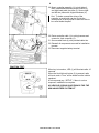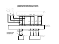
1
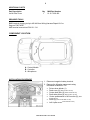
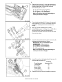
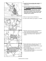
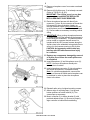
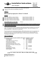
Installation Instructions Page 1 of 9 Phones, Navigation Accessory Development March 2004 These Installation Instructions supersede those dated February 2004. Changes to this revision are identified by a black bar. SUBJECT MINI Hands-Free System Kit - P/N 84 11 0 302 897 MODELS MINI Cooper (R50) w/o Harmon Kardon: MINI Cooper (R50) with Harmon Kardon*: MINI Cooper S (R53) w/o Harmon Kardon: MINI Cooper S (R53) with Harmon Kardon*: SUGGESTED INSTALLATION TIME: Vehicle Production 03/2002 - On Vehicle Production 09/2003 - On Vehicle Production 03/2002 - On Vehicle Production 09/2003 - On 1.0 hours *Note: This MINI Hands-Free Phone System with Bluetooth® Wireless Technology installation kit is not for vehicles with Harmon Kardon (HK) Audio Systems produced prior to 9/2003, as those vehicles will require a different wiring harness. “Never use any electronic device or make any inputs while driving that may distract you from driving safely. Pay attention to traffic laws and road conditions\situations. Safe vehicle operation is the driver's responsibility. Always wear your safety belt.” These instructions were developed specifically for MINI vehicles and are not to be compared to any existing instructions for vehicles other than MINI. No methods other than those specified in this document are to be used to install the MINI Hands-Free Phone System with Bluetooth® Wireless Technology in MINI vehicles. PARTS INFORMATION MINI Hands-Free Phone System Installation Kit Contents - P/N 84 11 0 302 897 Part Description Control Module Control Module Mounting Bracket Multi-Function Controller Controller Mounting Bracket Module Mounting Screws (M4 x 16mm) Multi-Function Controller - Mounting Tape Microphone Wiring harness* Female Bullet Connectors Cable ties (3mm x 104mm) Owner’s Manual Qty 1 1 1 1 2 2 1 1 3 6 1 MINI Part Number 84 11 0 302 896 84 11 0 302 903 84 11 0 302 902 84 11 0 302 901 N/A N/A 84 11 0 302 900 84 11 0 302 895 N/A N/A 84 11 0 302 892 DO IT RIGHT THE FIRST TIME, ON TIME, EVERY TIME Install Manual P/N 01 29 0 309 308 MINI, a division of North America, LLC © 2004 BMW of North America, LLC 2 ADDITIONAL PARTS Part Description Left A-Pillar Cover Qty 1 MINI Part Number 51 43 7 029 459 REQUIRED TOOLS BMW terminal crimping tool p/n 408 449 from Wiring Harness Repair Kit 3 or Snap-on P/N PWC47 AMP terminal removal tool P/N 611 134 COMPONENT LOCATION: A - Control Module B - Controller C – Microphone INSTALLATION PROCEDURE: 1. Disconnect negative battery terminal. 2. Remove the following components using information available in TIS: • Drivers knee bolster (1) • Dash cover (2) (Refer to RA51 45 051) • Center dash face (3) (Refer to RA62 21 001) • Radio side pillars (4) (Refer to RA51 16 198) • Center speedometer or NAV monitor (5) (Refer to RA62 21 001) • • Radio (6) (Refer to RA IS#65 11 030) Left A-pillar cover (Refer to RA51 43 201) Install Manual P/N 01 29 0 309 308 3 3. Remove the blue lock (1) from radio harness by releasing tab and sliding upwards, then remove following terminals (2) using AMP terminal removal tool p/n 611 134: Pin 12- Ground Connector (Brown) Pin 15- Battery +12V (Red/Brown) Pin 16- Ignition +12V (Violet/Blue) Note: wire colors may vary depending on vehicle production changes. 4. Cut original terminals off of 3 wires (1) removed from locations 12, 15 &16. Cut wire as close as possible to existing terminal to maintain wire length. 5. Strip 1/8” of wire shielding from 3 wires. 6. Using BMW terminal crimping tool p/n 408 449 or Snap-on PWC47 crimp new female bullet connectors included in kit onto each of the wires from previous step. 7. Insert the 3 terminals (4) into 3-pin connector (5) included with the harness as follows: IMPORTANT Pin 1 is identified by the straight edge of the connector Pin 1- Battery +12V (Red/Brown) Pin 2- Ignition +12V (Violet/Blue) Pin 3- Ground (Brown) Note: wire colors may vary depending on vehicle production changes. 8. Insert 5 wires from the hands-free kit harness (1) into the radio connector (2). To Radio From Harness Connector Pin Yellow (BAT) 15 Red (IGN) 16 Black (GND) 12 Violet (Mute) 10 Green (Tel ON) 11 9. Reinsert blue lock into radio harness connector. Install Manual P/N 01 29 0 309 308 4 10. Insert black 12-pin connector from hands-free kit harness (1) into lower right section of radio connector (2). 11. Connect male & female 3-pin connectors (3). Note: On vehicles equipped with Navigation and/or AUX Input the 12-pin connector (1) is already included in radio harness. It will be necessary to remove pins 6 & 12 from the hands-free kit harness 12-pin connector and insert them into the appropriate slots of the existing 12-pin connector. 12. Remove 2 upper screws to bulkhead (1). 13. Loosen 2 lower screws (2) to expose ¼” of thread. 14. Slide the 2 lower slots of the module bracket (1) onto 2 screws (2) loosened previously. 15. Install module bracket to bulkhead using 2 upper screws (3) removed previously. Tighten all 4 screws. 16. Route hands-free kit wiring harness up through radio cavity to bracket mounting location. 17. Insert and secure 18-pin connector (1) into handsfree kit module (2). 18. Secure control module (2) to module-bracket using 2 - M4x16 Screws (3). NOTE: A right-angle screwdriver is recommended to install screws into bracket. Install Manual P/N 01 29 0 309 308 5 19. Remove microphone cover from center overhead location. 20. Remove left A-pillar cover, if not already removed. (Refer to TIS RA 51 43 201) IMPORTANT: The A-Pillar cover is a one time use component and MUST BE REPLACED WITH A NEW PART ONCE REMOVED. 21. Route microphone harness with black 3-pin connector (1) from 18-pin connector of hands-free kit harness (2) along underside of dash, up through left-hand A-pillar (along windshield) and to microphone mount location in center overhead (3). Secure cable as necessary to existing vehicle wiring. 22. IMPORTANT: When routing microphone harness (1) along the left A-Pillar insure that the harness is routed along the windshield. The harness should not be routed in a manner that will cause it to interfere with the HPS, secure harness along the A-pillar close to the windshield using plastic ties to secure it to the harness running up the A-pillar. CAUTION: An improperly routed cable may interfere with HPS and cause serious injury in a collision. 23. Replace any components damaged by removal of A-pillar cover before the new A-pillar cover is reinstalled. 24. Insert Microphone (1) into Microphone cover (2). NOTE: Arrow on microphone should point towards front of vehicle. 25. Insert microphone connector (3) into microphone and install microphone in overhead console. Note: On vehicles equipped with a sunroof the location of the sunroof switch and microphone can be switched in order to place the microphone closer to the driver. 26. Reinstall radio using 4 original mounting screws. 27. Adhere strips of mounting tape (1) to top and bottom positions of button bracket (2). Trim excess tape as necessary. 28. Mount controller (3) to button bracket (2) with provided adhesive tape (1). Be sure to properly align controller to bracket before adhering. Install Manual P/N 01 29 0 309 308 6 29. Mount controller assembly (1) to right side of radio, sandwiched between center console (2) and right-hand radio trim pillar (3). Secure right and left trim pillars with original hardware (4). Hint: To better conceal the wiring of the controller, a small notch can be cut into the inside portion of the trim pillar to allow the wire to be routed inside the pillar. 30. Route controller cable (1) to wiring harness and connect to 4-pin connector (2). 31. Secure cable slack (4) with provided cable ties. 32. Reinstall all components removed for installation process. 33. Reconnect negative battery terminal FUNCTION TEST: When key is turned on, LED (1) will illuminate after 10 seconds. When the Hook/Unhook button (2) is pressed, radio will mute, and a “Tone” will be heard from the vehicle speakers. At voice prompt say, “SETUP”. If there is a voice response, installation is complete. NO VEHICLE CODING IS NECESSARY FOR THE MINI HANDSFREE SYSTEM KIT. Install Manual P/N 01 29 0 309 308 7 PAIRING PROCEDURE: Pairing is needed for phone recognition and to prevent other mobile phones from establishing an unwanted wireless connection. Mobile phones that are not paired will not operate with the system. Pairing only needs to be done once for a mobile phone unless the device is deleted from the system's memory. The MINI Hands-Free System searches first for the most recently paired phone stored in memory. The first mobile phone found will be connected to the system. Once this connection is established no other phone can be connected. Only one of five paired phones can be wirelessly connected to the system at a time IMPORTANT: Prior to starting the pairing procedure the Bluetooth Wireless Technology feature of your phone must be activated. This feature will enable your phone to discover or be discovered by other devices that utilize Bluetooth Wireless Technology. If the feature is not activated the pairing procedure cannot be completed. The methods of enabling this feature will vary for each model phone being utilized please refer to the owner’s manual of the phone being connected to the system for specific instructions on activating the Bluetooth feature/operation mode. Pairing Procedure and Pass code To pair a mobile phone enabled with Bluetooth® wireless technology to the hands-free system installed in your vehicle, turn on the vehicle's ignition, wait for the controller LED light to blink once, have your mobile phone pairing procedure available and follow these steps: 1. Prior to starting the pairing procedure the Bluetooth Wireless Technology feature of your phone must be activated. This feature will enable your phone to discover or be discovered by other devices that utilize Bluetooth Wireless Technology. If the feature is not activated the pairing procedure cannot be completed. IMPORTANT: The methods of enabling this feature will vary for each model phone being utilized, please refer to the owner’s manual of the phone being connected to the system for specific instructions on activating the Bluetooth feature/operation mode. 2. On controller press Send/Receive, wait for the beep and say, "SETUP" 3. System Response: "SELECT ONE OF THE FOLLOWING: PHONE PAIRING, CONFIRMATION PROMPTS OR LANGUAGE" audible beep 4. Say “PHONE PAIRING" 5. System Response: ”PLEASE, SELECT ONE OF THE FOLLOWING: PAIR OR DELETE THE CURRENT PHONE" audible beep 6. Say "PAIR" 7. System Response: "PLEASE, PAIR PHONE AS MENTIONED IN PHONE MANUAL" 8. The MINI Hands-Free System with Bluetooth® Wireless Technology will search for approximately two minutes for another device with the Bluetooth feature enabled and it’s discover mode activated. 9. To complete the pairing procedure, the mobile phone must be placed into the correct search/discover mode in order to be recognized by the hands-free system. Refer to the user’s guide of the phone being paired for instructions on activating the Bluetooth connection/search/discover feature. Install Manual P/N 01 29 0 309 308 8 IMPORTANT: Pairing will only be successful if the Bluetooth feature of the mobile phone is activated and the phone is placed into the correct search mode in order to locate other devices that utilize Bluetooth® wireless technology. 10. As a connection is established between the phone and the Hands-free system, most mobile phones will display a message like: “searching” Followed by "Mini HF" once the MINI Hands-Free System with Bluetooth® Wireless Technology is detected. 11. Press the YES/SEND key on the phone to accept "Mini HF" 12. Press YES/SEND key on the phone once more to accept "add to paired". 13. Enter the requested password/pass code - 0000 using phone keypad 14. On phone press YES/SEND key to accept the entered passcode. 15. The mobile phone will display "Mini HF pairing" to indicate the procedure is being completed. 16. The last step is modifying and/or accepting the "Mini HF" nametag given to the system. Once the YES/SEND key is pressed, pairing will be finalized. 17. Successful pairing is indicated by the prompt "PAIRING COMPLETED". 18. Approximately 15 seconds after the prompt, the LED light will stay on indicating an active mobile phone connection. To stop or cancel a pairing procedure that has been initiated, press Send/Receive. The procedure will be cancelled and the system will exit. TROUBLESHOOTING Symptom No Power to Controller or Controller does not illuminate with Key-on Radio does not Mute when Hook/Unhook button is pressed on controller No audio from speakers System does not respond to voice Commands Possible solution Blown Radio fuse in fuse panel Incorrect wiring to control module from radio harness Controller not connected to Control Module Incorrect wiring between control module and radio 12-pin audio connector not connected in rear of radio Incorrect harness for H/K audio-equipped vehicle Microphone not connected to phone harness Damaged wiring between control module and microphone Install Manual P/N 01 29 0 309 308 Wiring Schematic MINI Hands-Free System (Without HK as of 3/02 & With HK as of 9/03) Connection to Main Harness (Wires Removed from Radio Connector) N9 Radio IGN. Batt. 1 Gnd. 2 3 15 16 12 0.5 RT 0.5 SW 0.5 SW 11 10 0.5 GN 0.5 VI 13 4 Audio + X2519 X8 0.5 GE Audio - 6 12 X4 0.5 BL/SW 0.5 BL/BR X7 11 10 Batt. IGN. Mic + Mic - 18 1 Gnd. 7 Audio + X1 Audio - Hands-Free Phone Module Controller Inputs 9 14 1 0.5 SW 1 16 Mute Tel-On 0.5 SW NOTE: Wiring Diagram reflects the harness installed with the MINI Hands-Free System Mute X9 0.5 RT 0.5 GE Tel-On Gnd. IGN. Batt. X5 2 0.5 RT 2 15 0.5 GN 3 6 X1 0.5 GE 4 2 Microphone Multi-Function Controller