1
AIC-6915 Ethernet LAN Controller Programmer’s Manual
Instruction Formats
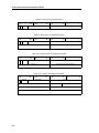
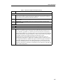
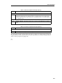
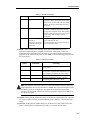
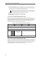
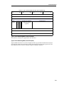
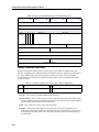
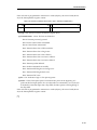
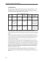
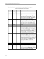
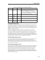
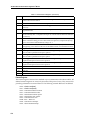
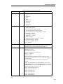
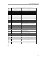
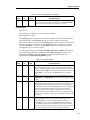
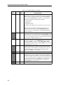
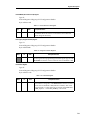
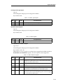
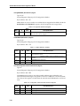
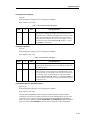
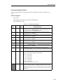
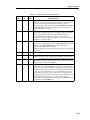
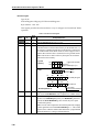
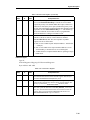
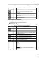
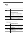
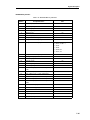
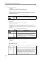
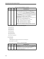
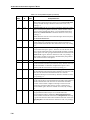
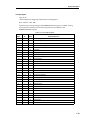
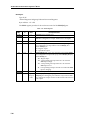
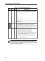
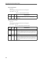
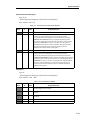
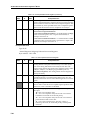
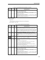
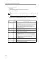
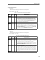
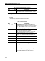
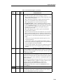
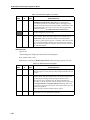
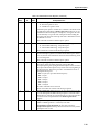
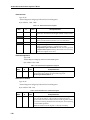
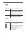
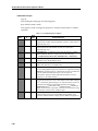
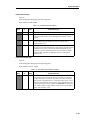
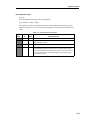
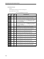
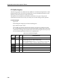
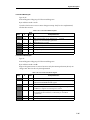
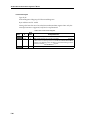
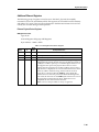
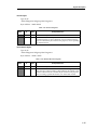
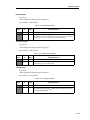
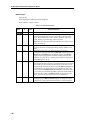
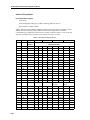
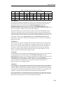
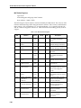
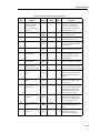
Table 5-2 describes the Instruction Formats.
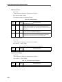
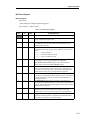
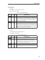
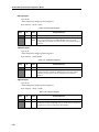
Table 5-2. Instruction Formats
Name
5-6
Bit Number
Description
Opcode 0
3:0
Execute - Execute instruction as specified by control fields
Opcode 1
3:0
BrToImmIfTrue - Branch to immediate address specified in
BRANCHADD field if ALU flag is true
Opcode 2
3:0
BrToImmIfFalse - Branch to immediate address specified in
BRANCHADD field if ALU flag is false
Opcode 3
3:0
BrToWreg3IfTrue - Branch to the location pointed to by WR3 if
ALU flag is True
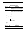
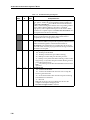
Opcode 4
3:0
BrToWreg3IfFalse - Branch to immediate address specified in
BRANCHADD field if ALU flag is False
Opcode 5
3:0
Write - Write ALU output to 8-bit address defined in
BRANCHADD[7:0]. If BRANCHADD[7] is set the write operation is
targeted to a register implemented in the GFP module. If the bit is
reset the target register is implemented externally.
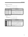
Opcode 6
3:0
Read - Read location pointed to by the address defined in
BRANCHADD[7:0], pass the data through the ALU and store it in
the working registers.
Opcode 7
3:0
Halt - Halt the processor. Wait for the assertion of ResetProcessor
input, then reset and start execution at address 0.
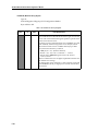
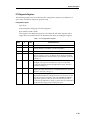
Opcode 8
3:0
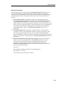
CheckIpv4ProtocolId - Special instruction for checking Ipv4
Protocol ID field, then branch to one of three possible addresses.
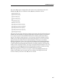
The GFP recognizes 3 Protocol IDs:
TCPFRAMEID = 8'h06, Branch address = BRANCHADD[7:0]
UDPFRAMEID = 8'h11, Branch address = DATA[7:0]
ICMPFRAMEID = 8'h00, Branch address = DATA[15:8]
Opcode 9
3:0
ReadIpv6ExtHeader - Special instruction for reading the Next
Header and Length fields of an Ipv6 extension header. After the
instruction is executed, WR2 stores the size of the extension header
in 16-bit halfword units minus 1 (for the first 16-bit already read).
WR3 stores the total size of the frame in bytes. WR4 stores the Next
Header field.