1
azur 540R V2.0
AV receiver
User’s manual
CONTENTS
Introduction .................................................................................................3
Limited warranty ........................................................................................4
Safety precautions .....................................................................................5
Important safety instructions ....................................................................6
Front panel connections ............................................................................8
Rear panel connections ...........................................................................10
Remote control ........................................................................................12
Surround Sound modes ...........................................................................14
Loudspeaker positioning .........................................................................15
Loudspeaker connections .......................................................................16
Audio connections ...................................................................................17
Video connections ....................................................................................17
Digital connections ..................................................................................18
6.1 Direct In .. ...........................................................................................18
6.1 Preamp Out .......................................................................................19
Front Input connections ...........................................................................19
Aerial connections ....................................................................................20
On-screen display (OSD) ..........................................................................20
OSD menus ...............................................................................................21
Surround Sound setup .............................................................................22
Operating instructions ..............................................................................26
Custom installation use ...........................................................................28
Reset/Back-up memory ...........................................................................28
Troubleshooting .......................................................................................29
2 Azur AV receiver
Technical Specifications ..........................................................................30
540R V2.0 AV receiver
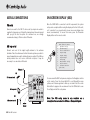
INTRODUCTION
Thank you for purchasing this Cambridge Audio Azur range AV receiver.
This 540R version 2 is part of our commitment to the on-going
development of the Azur range. We hope that you will appreciate the
results and enjoy many years of listening pleasure from it.
In addition, the 540R V2.0 also carries a 6.1 channel analogue input.
This feature allows for the connection of a DVD Audio or SACD player
equipped with a 5.1/6.1 output. This means that the 540R V2.0 is fully
equipped to make the most of these exciting new music formats.
About the 540R V2.0
As well as the full complement of audio inputs, the 540R V2.0 also
performs Composite, S-Video and Component Video switching. This
means that the 540R V2.0 can be used as a hub to route video signals
in addition to the audio ones.
The 540R V2.0 is designed to maximise multi-channel performance
without compromising on stereo reproduction. As such, the six 80W
discrete amplifiers are kept as separate as possible from the processing
and input stages. An oversized power supply ensures that the 540R
V2.0 can maintain a high power output into even difficult speaker loads
to ensure a powerful and effortless sound.
For this V2.0 model we have fitted an improved volume control IC, larger
PSU capacitors and made various improvements to the circuitry further
elevating the sound quality of the unit. The Video switching has also
been completely re-designed to give higher bandwidth compatible with
HDTV and the unit now features full On Screen Display.
A full range of digital and analog inputs are fitted to the 540R V2.0.
Digital inputs allow for the connection of suitably equipped DVD players,
satellite boxes and games consoles for decoding into stereo or digital
surround formats. Conventional analog stereo inputs allow the
connection of CD players and the like to ensure the best possible stereo
reproduction. The 540R V2.0 is also capable of decoding analog stereo
sources in Dolby Pro Logic® II and DTS Neo:6, for a convincing and
effective surround experience from an analog source. This ensures
sources such as analog televisions and VCRs can also make full use of
the 540R V2.0's surround capabilities.
All this proprietary engineering is housed within our low resonance,
acoustically damped chassis. An Azur Navigator remote control is also
provided, giving full remote control of your AV receiver in an attractive
and easy to use handset.
Your 540R V2.0 can only be as good as the system it is connected to.
Please do not compromise on your speakers or cabling. Naturally we
particularly recommend DVD/CD players or other source equipment
from the Cambridge Audio Azur range, which have been designed to the
same exacting standards as our receivers. Your dealer can also supply
excellent quality Cambridge Audio interconnects to ensure your system
realises its full potential.
Thanks for taking the time to read this manual, we do recommend you
keep it for future reference.
Matthew Bramble
Technical Director
Azur AV receiver 3
LIMITED WARRANTY
Cambridge Audio warrants this product to be free from defects in
materials and workmanship (subject to the terms set forth below).
Cambridge Audio will repair or replace (at Cambridge Audio's option) this
product or any defective parts in this product. Warranty periods may vary
from country to country. If in doubt consult your dealer and ensure that
you retain proof of purchase.
To obtain warranty service, please contact the Cambridge Audio
authorised dealer from which you purchased this product. If your dealer
is not equipped to perform the repair of your Cambridge Audio product,
it can be returned by your dealer to Cambridge Audio or an authorised
Cambridge Audio service agent. You will need to ship this product in
either its original packaging or packaging affording an equal degree of
protection.
Proof of purchase in the form of a bill of sale or receipted invoice, which
is evidence that this product is within the warranty period, must be
presented to obtain warranty service.
This Warranty is invalid if (a) the factory-applied serial number has been
altered or removed from this product or (b) this product was not
purchased from a Cambridge Audio authorised dealer. You may call
Cambridge Audio or your local country Cambridge Audio distributor to
confirm that you have an unaltered serial number and/or you purchased
from a Cambridge Audio authorised dealer.
This Warranty does not cover cosmetic damage or damage due to acts
of God, accident, misuse, abuse, negligence, commercial use, or
modification of, or to any part of, the product. This Warranty does not
cover damage due to improper operation, maintenance or installation,
or attempted repair by anyone other than Cambridge Audio or a
4 Azur AV receiver
Cambridge Audio dealer, or authorised service agent which is authorised
to do Cambridge Audio warranty work. Any unauthorised repairs will void
this Warranty. This Warranty does not cover products sold AS IS or WITH
ALL FAULTS.
REPAIRS OR REPLACEMENTS AS PROVIDED UNDER THIS WARRANTY
ARE THE EXCLUSIVE REMEDY OF THE CONSUMER. CAMBRIDGE AUDIO
SHALL NOT BE LIABLE FOR ANY INCIDENTAL OR CONSEQUENTIAL
DAMAGES FOR BREACH OF ANY EXPRESS OR IMPLIED WARRANTY IN
THIS PRODUCT. EXCEPT TO THE EXTENT PROHIBITED BY LAW, THIS
WARRANTY IS EXCLUSIVE AND IN LIEU OF ALL OTHER EXPRESS AND
IMPLIED WARRANTIES WHATSOEVER INCLUDING, BUT NOT LIMITED TO,
THE WARRANTY OF MERCHANTABILITY AND FITNESS FOR A PRACTICAL
PURPOSE.
Some countries and US states do not allow the exclusion or limitation of
incidental or consequential damages or implied warranties so the above
exclusions may not apply to you. This Warranty gives you specific legal
rights, and you may have other statutory rights, which vary from state to
state or country to country.
540R V2.0 AV receiver
SAFETY PRECAUTIONS
Checking the Power Supply Rating
For your own safety please read the following instructions carefully before attempting
to connect this unit to the mains.
Check that the rear of your unit indicates the correct supply voltage. If your mains
supply voltage is different, consult your dealer.
This unit is designed to operate only on the supply voltage and type that is
indicated on the rear panel of the unit. Connecting to other power sources may
damage the unit.
This equipment must be switched off when not in use and must not be used unless
correctly earthed. To reduce the risk of electric shock, do not remove the unit's
cover (or back). There are no user serviceable parts inside. Refer servicing to
qualified service personnel. If the power cord is fitted with a moulded mains plug
the unit must not be used if the plastic fuse carrier is not in place. Should you lose
the fuse carrier the correct part must be reordered from your Cambridge Audio
dealer.
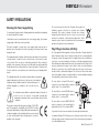
The lightning flash with the arrowhead symbol within an equilateral
triangle is intended to alert the user to the presence of un-insulated
‘dangerous voltage’ within the product’s enclosure that may be of
sufficient magnitude to constitute a risk of electric shock to
persons.
The exclamation point within an equilateral triangle is intended to
alert the user to the presence of important operating and
maintenance instructions in the service literature relevant to this
appliance.
This product complies with European Low Voltage (73/23/EEC)
and Electromagnetic Compatibility (89/336/EEC) Directives
when used and installed according to this instruction manual. For
continued compliance only Cambridge Audio accessories should
be used with this product and servicing must be referred to
qualified service personnel.
The crossed-out wheeled bin is the European Union symbol for
indicating separate collection for electrical and electronic
equipment. This product contains electrical and electronic
equipment which should be reused, recycled or recovered and
should not be disposed of with unsorted regular waste. Please
return the unit or contact the authorised dealer from whom you
purchased this product for more information.
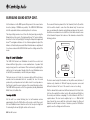
Plug Fitting Instructions (UK Only)
The cord supplied with this appliance is factory fitted with a UK mains plug fitted
with a 5 amp fuse inside. If it is necessary to change the fuse, it is important that
a 5 amp one is used. If the plug needs to be changed because it is not suitable for
your socket, or becomes damaged, it should be cut off and an appropriate plug
fitted following the wiring instructions below. The plug must then be disposed of
safely, as insertion into a mains socket is likely to cause an electrical hazard.
Should it be necessary to fit a 3-pin BS mains plug to the power cord the wires
should be fitted as shown in this diagram. The colours of the wires in the mains
lead of this appliance may not correspond with the coloured markings identifying
the terminals in your plug. Connect them as follows:
The wire which is coloured BLUE must be
connected to the terminal which is marked
with the letter ‘N’ or coloured BLACK.
The wire which is coloured BROWN must be
connected to the terminal which is marked
with the letter ‘L’ or coloured RED.
The wire which is coloured GREEN/YELLOW
must be connected to the terminal which is
marked with the letter ‘E’ or coloured GREEN.
If your model does not have an earth wire, then disregard this instruction.
If a standard 13amp (BS 1363) plug is used, a 5 amp fuse must be fitted, or if any
other type of plug is used a 5 amp fuse must be fitted, either in the plug or adaptor,
or on the distribution board.
Azur AV receiver 5
IMPORTANT SAFETY INSTRUCTIONS
Please take a moment to read these notes before installing your 540R
V2.0, as they will enable you to get the best performance and prolong
the life of the unit. Please retain these instructions for future reference.
Ventilation
IMPORTANT - The unit will become hot when in use. Please ensure that
there is ample ventilation around the unit. Leave at least 10cm of space
between the top, back and sides. Do not situate it on a rug or other soft
surface and do not obstruct the air inlet and outlet grilles on the
underside and top cover. Do not place in an enclosed area such as a
bookcase or in a cabinet.
Positioning
Choose the installation location carefully. Avoid placing it in direct
sunlight or close to a source of heat. Also avoid locations subject to
vibration and excessive dust, cold or moisture. Do not place the unit on
an unstable surface or shelf. The unit may fall, causing serious injury to
a child or adult as well as serious damage to the product. Do not place
a CD player or other equipment on top of the unit.
This unit must not be exposed to dripping or splashing water or other
liquids. No objects filled with liquid, such as vases, shall be placed on
the unit. In the event, switch off immediately, disconnect from the mains
supply and contact your dealer for advice.
Ensure that small objects do not fall through any ventilation grille. If this
happens, switch off immediately, disconnect from the mains supply and
contact your dealer for advice.
Electronic audio components have a running in period of around a week
(if used several hours per day). This will allow the new components to
settle down, the sonic properties will improve over this time.
6 Azur AV receiver
Grounding and polarisation
The unit may be equipped with a polarised alternating current line plug
(a plug having one blade wider than the other). This plug will fit into the
power outlet only one way. This is a safety feature. If you are unable to
insert the plug fully into the outlet, try reversing the plug. If the plug
should still fail to fit, contact your electrician to replace your obsolete
outlet. Do not defeat the safety purpose of the polarised plug. (North
America Only)
Power sources
The unit should be operated only from the type of power source
indicated on the marking label. If you are not sure of the type of powersupply to your home, consult your product dealer or local Power
Company.
This unit has been designed to be left in Standby mode when not in use,
this will increase the life of the amplifier (this is true with all electronic
equipment). If you do not intend to use this unit for a long period of time,
unplug it from the mains socket.
Power cord protection
Your power supply cord should be placed so that the power lead is not
likely to be walked on or pinched by items placed upon or against them,
paying particular attention to cords at wall plugs and where the power
lead exits from the unit.
Be sure to insert each power cord securely. To prevent hum and noise,
do not bundle the interconnect leads with the power cord or speaker
leads.
540R V2.0 AV receiver
Overloading
Attachments
Do not overload wall outlets or extension cord as this can result in a risk
of fire or electric shock. Overloaded AC outlets, extension cords, frayed
power cords, damaged or cracked wire insulation, and broken plugs are
dangerous. They may result in a shock or fire hazard.
Do not use attachments not recommended by your dealer as they may
cause harm to the unit.
Lightning
These units are not user serviceable, never attempt to repair,
disassemble or reconstruct the unit if there seems to be a problem. A
serious electric shock could result if this precautionary measure is
ignored. In the event of a problem or failure, please contact your dealer.
For added protection during a thunderstorm, or when it is left
unattended and unused for long period of time, unplug the unit from the
wall outlet and disconnect the antenna or cable system. This will prevent
damage to the unit from lightning and power-line surges.
Servicing
Contact the service department should any of these conditions occur:
Outdoor antenna grounding
- When the power-supply cord or plug is damaged.
If an outside antenna or cable system is connected to the product, be
sure the antenna or cable system is grounded so as to provide some
protection against voltage surges and built-up static charges. Section
810 of the National Electrical Code, ANSI/NIPA No. 70-1984 (section 54
of Canadian Electrical Code, Part 1) provides information with respect to
proper grounding of the mast and supporting structure, grounding of the
lead-in wire to an antenna-discharge unit, size of grounding conductors,
location of antenna-discharge unit, connection to grounding electrodes,
and requirements for the grounding electrode.
- If liquid has been spilled, or objects have fallen into the amp.
- If the unit has been exposed to rain or water.
- If the unit does not operate normally after following the operation
instructions, adjust only those controls that are covered by the
operation instructions.
- If the unit has been dropped or damaged in any way.
- When the unit exhibits a distinct negative change in performance.
Cleaning
Unplug the unit from the wall outlet before cleaning. To clean, wipe its
case with a moist, lint-free cloth. Do not use any cleaning fluids
containing alcohol, ammonia or abrasives. Do not spray an aerosol at or
near the unit.
IMPORTANT
If the unit is run at a very high level, a sensor will detect a temperature
rise and show "PROTECTION OVERLOAD" on the display. The unit will
then go into Standby mode. It cannot be switched on again until the
temperature has fallen to a more normal level.
Azur AV receiver 7
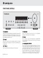
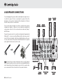
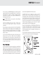
FRONT PANEL CONTROLS
Volume
azur 540R
AV Receiver
19
1
2
Standby / On
Phones
3
4
10
11
12
13
DVD
Video 1
Video 2
Video 3
14
15
16
Tuner FM/AM Tape/MD/CDR
CD/Aux
17
6.1 Direct
18
–
Tuning
+
Mode/Store
Video
Left
Right
20
Stereo
5
1
Dolby Digital EX/ Pro Logic II/
DTS ES
Neo 6
6
Standby/On
Switches the unit between Standby mode (indicated by dim power LED)
and On (indicated by bright power LED). Standby is a low power mode
where the power consumption is less than 10 Watts. The unit should be
left in Standby mode when not in use.
2
Phones
Allows for the connection of stereo headphones with a ¼" Jack plug.
Headphones with an impedance of between 32 and 600 ohms are
recommended.
3
Tuning +/-
Used to tune FM frequencies and skip presets in Tuner mode.
8 Azur AV receiver
7
DSP
Mode
Input
Mode
8
9
4
Video 3 inputs
Mode/Store
Press to cycle between Tuner modes (refer to the ‘Operating
Instructions’ of this manual for more information).
5
Stereo
Press to listen to a source in either analog stereo or digital (LPCM)
stereo (depending on the input mode) from the front left and right
loudspeakers only.
6
Dolby Digital EX / DTS ES
Press to select between various standard Dolby Digital or DTS surround
5.1 modes (with suitably encoded digital source material). Also selects
extended Dolby Digital EX and DTS ES modes which provide 6.1 output
with suitably encoded EX/ES material. These modes can only be
decoded from digital audio sources (via Coaxial or Optical inputs). An
Autodetect mode is also available which allows the 540R V2.0 to
automatically set itself to the appropriate mode for digital material.
540R V2.0 AV receiver
7
Pro Logic II / Neo:6
Press to decode suitable encoded analog stereo source material into
surround sound. Autodetection for these modes is not possible and they
must be manually selected.
8
DSP Mode
The 540R V2.0 can create a surround sound effect even from nonencoded material by Digital Signal Processing (DSP). Press this button to
choose one of the following surround sound effects: THEATER, HALL,
MOVIE, MUSIC or ROOM.
9
Input Mode
Press this button to toggle between analog or optical/coaxial digital
input types for the currently selected source. The 540R V2.0 remembers
the input type selected for each source when you return to that source.
10
DVD
Press to select the DVD source equipment for output through the 540R
V2.0.
11
Video 1
Press to select the source equipment connected to Video 1 for output
through the 540R V2.0.
12
Video 2
Press to select the source equipment connected to Video 2 for output
through the 540R V2.0.
13
Video 3
14
Tuner FM/AM
Press to select the tuner for output through the 540R V2.0. In Tuner
mode also use this button to switch between FM and AM modes.
15
Tape/MD/CDR
Press to select the recording device connected to the Tape/MD/CDR
input for output through the 540R V2.0.
16
CD/Aux
Press to select the CD or other source equipment connected to CD/Aux
on the rear panel for output through the 540R V2.0.
17
6.1 Direct
Press to select a 5.1 or 6.1 DVD-A or SACD player connected to the 6.1
Direct In sockets.
18
Infrared sensor
Receives IR commands from the supplied Azur remote control. A clear
unobstructed line of sight between the remote control and the sensor is
required.
19
Volume
Use to increase/decrease the level of the sound from the outputs of the
540R V2.0.
20
Video 3 input sockets
Allows a video camera recorder/video games console to be connected
and selected by the Video 3 source button.
Press to select the source equipment connected to Video 3 (on the front
panel) for output through the 540R V2.0.
Azur AV receiver 9
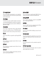
REAR PANEL CONNECTIONS
2
azur 540R V2.0
AV Receiver
3
TV/Mon Out
5
Optical In
S-Video In
Video 1
DVD
CD
Video 1/Video 2 DVD
S-Video
Video 2
This device
complies with
part 15 of
FCC rules
Manufactured
in an ISO9002
approved facility
7
AM
Loop
300Ω
CD
Video 2
Tuner
4
Video 1
RS232C
20
Y
Cr/Pr
Cb/Pb
Y
Cr/Pr
Cb/Pb
Off
R
Power AC
L
SL
Cen
SB
C
SL
L
Sur
Right
Right
Sur
Back
Centre
14
R
Video 2
Video 1
DVD
Tape Play
Tape Rec
R
SW
SR
6.1 Direct In
18
FM/AM antenna
TV/Mon outputs
Composite - Connect to your television via RCA phono cable to display
the picture of any composite video connected unit.
These outputs are also used to view the 540R V2.0’s on-screen setup
menu.
S-Video inputs
Connect the S-Video outputs from the source equipment.
10 Azur AV receiver
Power
13
Left
L
CD/Aux
12
Y
On
Sur
Left
Coax Out
S-Video - Connect to your television via S-Video cable to display the
picture of any S-Video connected unit.
3
Cb/Pb
Control
Bus
10
All tuner antenna connections are made here. Refer to the ‘Antenna
Connections’ section of this manual for more information.
2
Designed in London, England
www.cambridge-audio.com
In
Tape
19
1
Component Video Out
8
11
Coax In
Audio In
Risque de choc electrique
Ne pas ouvrir
6
Component Video In
Video 1/Video 2
Reset
DVD
L
Vorm öffnen des gërates
Netzstecker ziehen
9
Video 1/Video 2 DVD
Composite Video In
Caution / Avis /Achtung
Risk of electric shock
Do not open
DVD
Cr/Pr
FM 75Ω
Composite
1
Optical
Out
SB
17
SW
SR
6.1 Preamp Out
Speaker Impedance 4-8 Ohms
16
4
Power Rating: 230V AC 50Hz
Max Power Consumption: 615W
R
Serial No. label fitted on underside
15
Composite Video inputs
Connect the Composite Video outputs from the source equipment.
5
Component Video inputs
Connect the Component Video outputs from the source equipment.
Note: The preferred connection method for video sources is always
Component Video (highest quality) then S-Video then Composite Video.
DVD Component Video sources often also support Progressive Scan
which gives better picture quality if supported by both your DVD player
and TV.
6
Component Video Out
Connect to the Cr/Pr, Cb/Pb, & Y terminals of a television set.
Note: There is no on-screen setup menu present on the Component
Video outputs.
540R V2.0 AV receiver
7
Optical In
Connect to the digital optical (Toslink) outputs from source equipment.
8
Optical Out
Connect to the digital optical (Toslink) input of an external recording
device (eg MD/CDR etc) to record from the selected digital audio source.
9
Coax In
Connect to the digital coaxial (SPDIF) outputs from source equipment.
10
Coax Out
Connect to the digital coaxial (SPDIF) input of an external recording
device (eg MD/CDR etc) to record from the selected digital audio source.
11
Control Bus In
Allows un-modulated commands from multi-room systems or other
components to be received by the 540R V2.0.
12
Reset
Resets all factory default settings. Refer to the ‘Reset/Back-up memory’
section of this manual for more information.
13
Power On/Off
15
Speaker terminals
Connect to loudspeakers with an impedance of between 4-8 ohms.
16
6.1 Preamp Out
Connect to the 6.1 (or 5.1) channel input terminals of another amplifier
system, separate power amps, subwoofer or active loudspeakers.
17
6.1 Direct In
Connect to the 6.1 (or 5.1) channel output terminals of a DVD player
with built-in surround sound decoding for playing DVD-A or SACD.
18
Tape
Connect the Tape Play sockets to the line output terminals of a Tape
deck, MD player, CD-R etc. Connect the Tape Rec sockets to the line
input terminals of a Tape deck, MD player, CD-R etc.
19
Audio inputs
Connect to the audio line output terminals of a source device (eg CD,
DVD player etc).
20
RS232C
For use by an installer/dealer for software updates.
Switches the unit on and off.
14
Mains power lead
Once you have completed all connections, plug the AC power lead into
an appropriate mains socket. The AV receiver is now ready for use.
Azur AV receiver 11
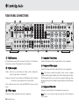
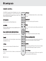
REMOTE CONTROL
The 540R V2.0 is supplied with an Azur Navigator remote control.
Insert the supplied AAA batteries to activate. For full details of the
various adjustment functions available from the remote, refer to
the later sections of this manual.
Standby/On
Switches the unit between On and Standby mode.
CH Select
Input
Mode
Press to select individual channels, then use volume to balance
speakers.
Stereo
PL II
Neo 6
DD EX
DTS ES
DSP
Mode
Dynamic
LFE
Trim
Test
Tone
CH
Select
Sub
On/Off
SPK
Setup
Delay
Sub On/Off
Press to turn on/off the output of the subwoofer.
Input Mode
Delay
Switches the 540R V2.0 between analog and digital inputs for the
currently selected source.
Press to set the delay times when setting up surround sound
speakers.
Vol
Stereo, PLII/NEO 6, DD EX/DTS ES, DSP Mode
SPK Setup
Enter
Vol
Press to change the surround sound speaker settings.
See button details as listed in the ‘Front Panel Controls’ section.
Dynamic
Press repeatedly to reach the desired dynamic compression range
(Dolby Digital mode only).
Tuner
AM/FM
Bass
Treble
6.1
Direct
PTY
APS
Display
Stereo
Mono
Store
Mode
DVD
Video 1
Video 2
Video 3
Tape
MD/CDR
CD
Aux
LFE Trim
Press to access the Low Frequency Trim (subwoofer) mode.
Test Tone
Press to access the test tones to balance your surround sound
speakers.
12 Azur AV receiver
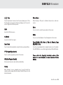
On-screen Display (OSD)
Press to access an on-screen set-up menu when connected to a
monitor/screen via composite or S-video connections.
Mute
Mutes the audio on the AV Receiver. The mute mode is indicated
by the channel LED flashing. Press again to cancel mute.
Volume
Increase or decrease the volume of the AV receiver output. Also
used as up/down in the OSD setup menu.
540R V2.0 AV receiver
Tune
Press the right arrow to increase tuner frequency/change preset. Press
the left arrow to decrease tuner frequency/change preset. Also used to
scroll left/right in the OSD setup menu.
Stereo Mono
When listening to FM, press to alternate between stereo and mono
modes.
Store
Enter
Press to store the current frequency when in Tuner mode.
Used in the OSD setup menu.
Mode
6.1 Direct
Press to select Auto/Manual or Preset tuning when in Tuner mode.
Selects the 5.1/6.1 Direct input.
Bass Treble
Press for bass/treble adjustment, using the Volume up/down buttons.
Tuner FM/AM, DVD, Video 1, Video 2, Video 3, Tape
MD/CDR, CD Aux
Press the corresponding button to change the input source. Pressing the
Tuner AM/FM button a second time toggles between FM and AM modes.
PTY (Program Type Search)
Press to search by program type when in Tuner mode.
APS (Auto Program Search)
Please refer to the ‘Operating Instructions’ section of this
manual for more information on some functions of these
buttons.
Allocates and memorises radio stations automatically.
Display
When listening to source equipment press to view the input type
(optical/coaxial or analog). When listening to FM with RDS, press to view
station information.
Azur AV receiver 13
SURROUND SOUND MODES
The 540R V2.0 has several music and home-cinema listening modes
available, all designed to reproduce “surround sound” effects,
dependant on the input signal and speaker setup:
Stereo
Only the Front Left and Front Right speakers (and subwoofer if selected)
have output in this mode. If an analog source is selected you will be
listening to pure analog stereo with no digital signal processing. If a
digital source is selected the 540R V2.0 will act as a digital to analog
converter and play back stereo LPCM as output by CD players etc.
for greater image depth and more solid sound localisation behind the
listener. All channels are discretely encoded digitally for the best
possible surround sound effect. DTS-ES Discrete requires a DTS-ES
Discrete encoded disc.
DTS-ES Matrix (6.1)
Another enhanced form of DTS, ES Matrix also provides an extra channel
(Surround Back) but instead the extra channel is inserted into the left
and right surround channels in a matrix process. DTS-ES Matrix requires
a DTS-ES Matrix encoded disc.
Dolby Digital (5.1)
Pro Logic II
Provides (up to) 5.1 output from suitable encoded Dolby Digital material
using 5 main speakers (Left Front , Right Front , Centre, Left Surround,
Right Surround) and a subwoofer. Decoding Dolby Digital requires a
Dolby Digital encoded DVD disc and a digital connection from the 540R
V2.0 to the source equipment (Such as a DVD player).
A newer version of Dolby Pro Logic which is able to recreate 5.1 surround
sound from suitable encoded analog source material. The source
material is stereo (and can be played as such) but also has special
encoding that allows the 540R V2.0 to decode a 5.1 surround sound
output. There are 5 standard modes: Movie, Music, Virtual, Pro Logic
Emulation and Matrix.
DTS (5.1)
DTS also provides (up to) 5.1 output from suitable encoded DTS material
using 5 main speakers (Left front , Right front , Centre, Left Surround,
Right Surround) and a subwoofer. Decoding DTS requires a suitably
encoded DTS disc and a digital connection from the 540R V2.0 to the
source equipment.
Dolby Digital EX (6.1)
An enhanced form of Dolby Digital, DD EX provides an extra channel
(Surround Back) for greater image depth and more solid sound
localisation behind the listener. DD EX requires a DD EX encoded disc.
DTS-ES Discrete (6.1)
An enhanced form of DTS, ES provides an extra channel (Surround Back)
14 Azur AV receiver
DTS Neo:6
A DTS technology which is able to recreate 6.1 surround sound from
suitable encoded analog source material. The source material is stereo
(and can be played as such) but also has special encoding that allows
the 540R V2.0 to decode a 6.1 surround sound output. There are 2
standard modes: Cinema and Music.
DSP modes
These modes allow a realistic surround-sound experience from source
material that has no encoding at all. The surround sound effect is
achieved by Digital Signal Processing of the Analog or Digital stereo
source used. Five modes are possible: Theater, Hall, Movie, Music and
Room.
540R V2.0 AV receiver
LOUDSPEAKER POSITIONING
The diagram shows a typical example of a 5.1/6.1 loudspeaker setup.
Always adjust the speaker and listening positions until you are happy
with the sound. Please refer to the loudspeaker and subwoofer manuals
for more detailed positioning information.
1 Front Left and Right speakers - For stereo and multi-channel sound.
Angle towards the listening position.
2 Centre speaker - For dialogue and centre sounds. Position at a
similar height to the front left and right speakers (above or below the
TV/monitor). Using a centre speaker from the same
manufacturer/range as used used for the front left and right speakers
is advisable. This “timbre matching” allows surround effects to flow
more naturally from left to right without obvious transitions between the
speakers.
1
5
1
2
5.1/6.1
3 Surround Left and Right speakers - For ambient and multi-channel
sound. Floorstanding speakers should be angled towards the listening
position. Bookshelf/standmount speakers should be wall mounted or
used with dedicated speaker stands, positioned at or above ear height.
To set the required delay between speakers for surround sound modes,
please refer to the ‘Surround Sound Setup’ section of this manual.
4 Surround Back speaker - Optional sixth channel speaker, required
for enjoying Dolby® Digital EX or DTS®-ES audio. Improves the quality of
sound effects by filling the gap between the surround left and rear right
speakers. Position the speaker firing towards the front of the room.
5 Subwoofer - For improving the bass in your system, as well as
reproducing LFE cinema effects when playing Dolby Digital or DTS
encoded discs. Your subwoofer can often be placed almost anywhere in
the room as bass is less directional, but experimentation with
positioning is recommended.
3
4
*
3
* Optional “6th” speaker
Azur AV receiver 15
LOUDSPEAKER CONNECTIONS
To avoid damaging the speakers with a sudden high-level signal, be sure
to switch the power off before connecting the speakers. Check the
impedance of your speakers. Speakers with an impedance of between
4 and 8 ohms (each) are recommended.
Front right
speaker
Front left
speaker
Surround
right speaker
The coloured speaker terminals are positive (+) and the black speaker
terminals are negative (-). Make sure correct polarity is maintained at
each speaker connector or the sound can become weak and “phasey”
with little bass.
Prepare the speaker cords for connection by stripping off approximately
10mm (3/8”) or less (no more than 10mm, as this could cause a shortcircuit) of the outer insulation. Twist the wire tightly together so there are
no loose ends. Unscrew the speaker terminal knob, insert the speaker
cable, tighten the knob and secure the cable.
DVD
Surround
left speaker
Component Video In
Video 1/Video 2
Component Video Out
Designed in London, England
www.cambridge-audio.com
Reset
Cr/Pr
Cb/Pb
Y
Cr/Pr
Cb/Pb
Y
Cr/Pr
Cb/Pb
Y
On
Control
Bus
Power
Sur
Left
Left
Off
In
Power AC
Cen
SB
SW
t In
SB
C
SL
L
SW
SR
6.1 Preamp Out
Sur
Right
Right
Sur
Back
Note: All connections are made via loudspeaker cable, except if using an
active subwoofer which would be connected via a standard RCA phono
cable. Banana Plugs (4mm standard) connected to the speaker cable
are recommended for direct insertion into the speaker terminals.
Speaker Impedance 4-8 Ohms
Power Rating: 230V AC 50Hz
Max Power Consumption: 615W
Serial No. label fitted on underside
Phono/RCA cable
Powered
subwoofer
16 Azur AV receiver
Centre
R
Surround back
speaker
Front centre
speaker
540R V2.0 AV receiver
AUDIO CONNECTIONS
VIDEO CONNECTIONS
Note: Do not plug in the mains power lead or turn the unit on until all
connections have been made.
Three types of video connections can be made on the 540R V2.0:
Composite (1), S-Video (2) and Component (3). For best picture quality
we recommend making Component video connections, then in declining
order of quality, S-Video connections and then Composite video
connections. The 540R V2.0 does not provide conversion between
Composite, S-Video or Component video formats (e.g. if you are
watching a S-Video input from a DVD, you must view it from the S-Video
output on the 540R V2.0).
Connect to source equipment using stereo phono cables (stereo 2RCA2RCA). Tape/MD/CDR recorder/players require two sets of stereo
phono/RCA cables, one for recording, one for listening.
Tape player/recorder
TV/Monitor
DVD player
Optical In
S-Video In
Video 1
DVD
CD
Video 1/Video 2 DVD
Optical
Out
DVD
Component Video In
Video 1/Video 2
Component Video Out
Designed in London, England
This device
complies with
part 15 of
FCC rules
Manufactured
in an ISO9002
approved facility
Cb/Pb
Y
Cr/Pr
Cb/Pb
Y
Cr/Pr
Cb/Pb
Video 1/Video 2 DVD
Power
Left
Off
Tuner
DVD
Composite Video In
Coax In
Tape
Caution / Avis /Achtung
Risk of electric shock
Do not open
RS232C
L
Risque de choc electrique
Ne pas ouvrir
In
Audio In
Coax Out
Power AC
L
SL
Cen
SB
C
SL
L
Sur
Right
Right
This device
complies with
part 15 of
FCC rules
Manufactured
in an ISO9002
approved facility
AM
Loop
300Ω
Video 1
DVD
Tape Play
Tape Rec
R
SR
SW
6.1 Direct In
SB
SW
SR
6.1 Preamp Out
CD
Optical
Out
DVD
Centre
Power Rating: 230V AC 50Hz
Max Power Consumption: 615W
R
Speaker Impedance 4-8 Ohms
Serial No. label fitted on underside
Cb/Pb
Component Video In
Video 1/Video 2
Component Video Out
Designed in London, England
www.cambridge-audio.com
Y
Cr/Pr
Cb/Pb
Y
Cr/Pr
Cb/Pb
Y
On
Control
Bus
Video 1/Video 2 DVD
Power
Left
Off
Video 1
DVD
In
Composite Video In
Coax In
Audio In
Risque de choc electrique
Ne pas ouvrir
Vorm öffnen des gërates
Netzstecker ziehen
Coax Out
Tape
Power AC
L
Cen
SB
SR
SW
6.1 Direct In
SB
SL
C
SL
SW
SR
6.1 Preamp Out
L
Sur
Right
Right
L
R
Sur
Back
R
CD/Aux
Video 2
Video 1
Phono cable (2RCA-2RCA)
1
CD player
Video 1/Video 2 DVD
Sur
Left
Video 2
Caution / Avis /Achtung
Risk of electric shock
Do not open
Video 2
CD
L
Sur
Back
R
CD/Aux
DVD
Reset
Tuner
L
R
Video 1
Cr/Pr
On
Control
Bus
Sur
Left
Video 1
Optical In
S-Video In
Video 2
FM 75Ω
Y
Composite
Composite
CD
Video 2
Vorm öffnen des gërates
Netzstecker ziehen
TV/Mon Out
Reset
Cr/Pr
AM
Loop
300Ω
azur 540R V2.0
AV Receiver
www.cambridge-audio.com
S-Video
Video 2
Component cable
(3RCA-3RCA)
3
S-Video
TV/Mon Out
FM 75Ω
RS232C
azur 540R V2.0
AV Receiver
S-Video
cable
2
Phono cable (2RCA-2RCA)
DVD player
DVD
Tape Play
Tape Rec
R
Single 75 ohm
Phono cable
(RCA-RCA)
Centre
Power Rating: 230V AC 50Hz
Max Power Consumption: 615W
R
Speaker Impedance 4-8 Ohms
Serial No. label fitted on underside
Component cable
(3RCA-3RCA)
DVD player
TV/Monitor
DVD player
TV/Monitor
Azur AV receiver 17
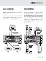
DIGITAL CONNECTIONS
6.1 DIRECT IN
Two types of digital audio connections can be made to the 540R V2.0,
Optical/Toslink and Coaxial/SPDIF. Either type can be used for each
source as the 540R V2.0 is able to convert between the two. Only one
connection type should be used per source.
To listen to multi-channel DVD Audio player or SACD discs connect your
DVD/SACD player to the 6.1 Direct In sockets.
Whichever type is used to connect to the digital inputs, both the
coaxial/SPDIF and optical/toslink outputs on the 540R V2.0 will be active.
CD player
Optical In
S-Video In
Video 1
DVD
CD
Video 1/Video 2 DVD
Optical
Out
DVD
Component Video In
Video 1/Video 2
Component Video Out
Designed in London, England
www.cambridge-audio.com
S-Video
Video 2
This device
complies with
part 15 of
FCC rules
Manufactured
in an ISO9002
approved facility
CD
Cb/Pb
Y
Cr/Pr
Cb/Pb
Y
Cr/Pr
Cb/Pb
Y
Video 1/Video 2 DVD
Power
Left
Off
Video 1
DVD
Coax In
Audio In
RS232C
Caution / Avis /Achtung
Risk of electric shock
Do not open
Coax Out
Tape
L
Risque de choc electrique
Ne pas ouvrir
In
Composite Video In
Power AC
L
SL
Cen
SB
C
SL
L
Sur
Right
Right
Video 2
Video 1
DVD
Tape Play
R
Tape Rec
SR
SW
6.1 Direct In
SB
SW
SR
6.1 Preamp Out
DVD
This device
complies with
part 15 of
FCC rules
Manufactured
in an ISO9002
approved facility
AM
Loop
300Ω
CD
Video 1/Video 2 DVD
Optical
Out
DVD
Cb/Pb
Component Video In
Video 1/Video 2
Component Video Out
Designed in London, England
www.cambridge-audio.com
Y
Cr/Pr
Cb/Pb
Y
Cr/Pr
Cb/Pb
Y
On
Control
Bus
Video 1/Video 2 DVD
Power
Sur
Left
Left
Off
Video 2
Tuner
Caution / Avis /Achtung
Risk of electric shock
Do not open
Centre
Power Rating: 230V AC 50Hz
Max Power Consumption: 615W
Risque de choc electrique
Ne pas ouvrir
Serial No. label fitted on underside
Vorm öffnen des gërates
Netzstecker ziehen
R
Speaker Impedance 4-8 Ohms
CD
Reset
Video 1
DVD
In
Composite Video In
Coax In
Audio In
Tape
L
Sur
Back
R
CD/Aux
Video 1
Cr/Pr
L
R
Optical In
S-Video In
Video 2
On
Control
Bus
Sur
Left
Video 2
Tuner
Vorm öffnen des gërates
Netzstecker ziehen
TV/Mon Out
FM 75Ω
Composite
Composite
AM
Loop
300Ω
azur 540R V2.0
AV Receiver
Reset
Cr/Pr
FM 75Ω
S-Video
TV/Mon Out
Optical cable
(OPT-OPT)
OR
RS232C
azur 540R V2.0
AV Receiver
Use Volume up/down on the remote to adjust the relative level of each
input channel in turn by -10dB to +10dB in 1dB steps. If no adjustment
is made for 5 seconds the unit saves the settings and returns to its
normal state. Note that any changes made are saved and will affect all
surround sound modes.
DVD player
OR
As any signals connected to the 6.1 Direct Input (multi-channel DVD-A /
SACD etc.) will have been decoded by an external unit it may be necessary
to adjust the relative levels of each channel when listening to this input.
This can be done using the CH Select button on the remote, the 540R
V2.0’s front panel display will rotate round each channel in turn.
Coax Out
Power AC
L
Cen
SB
SR
SW
6.1 Direct In
SB
SL
C
SL
SW
SR
6.1 Preamp Out
L
Sur
Right
Right
L
R
Sur
Back
R
CD/Aux
Video 2
Video 1
DVD
Tape Play
Tape Rec
R
Centre
Power Rating: 230V AC 50Hz
Max Power Consumption: 615W
R
Speaker Impedance 4-8 Ohms
Serial No. label fitted on underside
OR
Phono cable (2RCA-2RCA)
OR
MD/DVD-R/CD-R
18 Azur AV receiver
DVD-A player or SACD multi-channel
player 5.1 or 6.1 connections
540R V2.0 AV receiver
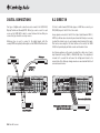
6.1 PREAMP OUT
FRONT INPUT CONNECTIONS
To connect external power amplifiers, use Phono/RCA leads connected
to the 6.1 Preamp Outputs on the rear panel.
The front panel Video 3 input is for temporary connections to video
games consoles etc. Remove the cap to access the Video 3 inputs, and
connect to a video game or video camera’s outputs using a composite
video cable and stereo phono cable (RCA-RCA).
Set the Pre Out setting in the Output Setup OSD menu to 'Pre Out' rather
than 'Normal'. This mutes the internal power amplifiers as they are not
being used.
Volume
azur 540R
AV Receiver
DVD
Video 1
Video 2
Video 3
Tuner FM/AM Tape/MD/CDR
CD/Aux
6.1 Direct
Video
Stereo
azur 540R V2.0
AV Receiver
TV/Mon Out
Optical In
S-Video In
Video 1
DVD
CD
Video 1/Video 2 DVD
CD
Video 1/Video 2 DVD
Optical
Out
DVD
Component Video In
Video 1/Video 2
Manufactured
in an ISO9002
approved facility
Left
Right
Video 3 inputs
Designed in London, England
www.cambridge-audio.com
Composite
Cb/Pb
Y
Cr/Pr
Cb/Pb
Y
Cr/Pr
Cb/Pb
Y
On
Control
Bus
Power
Sur
Left
Left
Off
Video 2
Tuner
Caution / Avis /Achtung
Risk of electric shock
Do not open
Risque de choc electrique
Ne pas ouvrir
Vorm öffnen des gërates
Netzstecker ziehen
Video 1
DVD
In
Composite Video In
Coax In
Audio In
RS232C
This device
complies with
part 15 of
FCC rules
Input
Mode
Reset
Cr/Pr
FM 75Ω
AM
Loop
300Ω
DSP
Mode
Component Video Out
S-Video
Video 2
Dolby Digital EX/ Pro Logic II/
DTS ES
Neo 6
Tape
L
L
R
R
CD/Aux
Video 2
Video 1
DVD
Tape Play
Coax Out
Power AC
L
Tape Rec
R
SL
Cen
SR
SW
6.1 Direct In
SB
SB
C
SW
SL
SR
6.1 Preamp Out
L
Sur
Right
Right
Sur
Back
Centre
Power Rating: 230V AC 50Hz
Max Power Consumption: 615W
R
Speaker Impedance 4-8 Ohms
Serial No. label fitted on underside
Composite
video
cable
Stereo
phono
cable
(RCA-RCA)
Phono cable (2RCA-2RCA)
Power amplifier
Video games console
(or video camera recorder)
Azur AV receiver 19
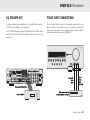
AERIAL CONNECTIONS
ON-SCREEN DISPLAY (OSD)
FM aerial
Once the 540R V2.0 is connected to all AV components, the system
setup can be completed either using the display on the front of the unit,
or if connected to a screen/monitor, via an on-screen display setup
menu (recommended). To access this menu, press the On-screen
Display button on the remote control.
Connect an aerial to the FM 75 ohm socket (a simple wire aerial is
supplied for temporary use). Extend the lead and move the aerial around
until you get the best reception. For continued use, we strongly
recommended using a 75 ohm outdoor FM aerial.
AM loop aerial
Connect each end of the single length antenna to the antenna
terminals. Place the antenna as far from the main system as possible to
prevent unwanted noise and to obtain optimum reception. If the AM loop
aerial provided does not receive sufficient reception, it may be
necessary to use an outdoor AM aerial.
azur 540R V2.0 Menu
1.
Speaker Config
2.
Speaker Dealy
3.
Level Calibration
4.
Input Setup
5.
Output Setup
6.
Input Assign
7.
OSD Setup
8.
Bass/Treble Config
9.
Sub Crossover
10. Software Version
(Quit OSD)
Vol
Enter
Vol
FM aerial
OR
azur 540R V2.0
AV Receiver
TV/Mon Out
S-Video In
Video 2
Video 1
S-Video
FM external aerial
This device
complies with
part 15 of
FCC rules
AM loop aerial
Manufactured
in an ISO9002
approved facility
Composite
FM 75Ω
AM
Loop
300Ω
Video 2
Tuner
Video 1
Composite Video
Audio In
To move around the OSD setup menu, simply use the Navigator controls
on the remote. Press the Arrow right/left to scroll through the menu
options, and Volume up/down to move up or down. Press the centre
Enter button to progress into a sub-menu. Press the OSD button to save
the settings and exit the setup menu.
Risque de choc electrique
Ne pas ouvrir
Vorm öffnen des gërates
Netzstecker ziehen
AM external aerial
Ground
20 Azur AV receiver
RS232C
L
Caution / Avis /Achtung
Risk of electric shock
Do not open
OR
R
CD/Aux
Video 2
Video 1
Note: The OSD setup menu is only available on a
screen/monitor connected via S-Video or Composite inputs.
540R V2.0 AV receiver
OSD MENUS
Speaker Configuration
OSD Setup
Assign the size of the speakers in your system (Small, Large or None if
not used).
TV format - Choose PAL (UK/Europe) or NTSC (Canada/USA) depending
on your TV type.
Speaker Delay
Background - Choose a blue screen or video source as the background
image for the OSD setup menu.
Set delay for your speakers according to their positions in your room.
This is calculated in milliseconds per metre. Please refer to the
‘Surround Sound Setup’ section of this manual for more information on
these speaker setup menus.
Level Calibration
Select to send a test tone signal through individual speakers. Adjust the
output to obtain the best sound. Please refer to the ‘Surround Sound
Setup’ section of this manual for more information on these speaker
setup menus.
Input Setup
Assign the audio source inputs to be digital or analog each time they are
selected. Video 3, Tuner, Tape, and 6.1 Direct will always be analog.
Output Setup
OSD Video - If Video selected for the background, choose the video
source (Composite or S-Video).
Language - Scroll through the available languages for the OSD setup
menu and press the Enter button to select.
Bass/Treble Configuration
Increase/decrease the bass/treble tone control settings.
Sub Crossover Frequency
Set the frequency at which bass sounds are to be sent to the subwoofer
(range 40Hz - 200Hz).
Software Version
Displays the current loaded software version.
If an external amplifier is connected via the 6.1 Preamp out sockets,
select ‘Preamp Out’ to mute the internal amplifiers.
Input Assign
Assign the Component video and/or digital audio source inputs for Video
1/Video 2.
Azur AV receiver 21
SURROUND SOUND SETUP
To setup the 540R V2.0 for surround sound use it is necessary to
perform 3 steps to match the unit to your speaker package type and
configuration. The required steps are:
1. Speaker Types - tell the 540R V2.0 how many and what type of
speakers are connected ('Large' or 'Small' in terms of bass response).
2. Delay Times - set up a delay time for the rear surround and/or centre
speakers so that the sound arrives at the listening position at the
right time (for each speaker) for the best surround sound effect.
3. Level Calibration - adjust the relative level of each speaker to take
into account any difference in efficiency or speaker type between
each speaker.
Optionally, when using the unit and after having performed the 3 stages
above you can then perform two other surround sound adjustments:
• Trimming the Low Frequency Effect (LFE) level to taste/circumstances.
• Applying Dynamic Range Control (DRC) to reduce the volume range of
loud to quiet passages in movie soundtracks.
These two extra adjustments can be made where it might be desired to
reduce the bass output level and/or the maximum difference in
loudness between quiet and loud passages in the movie. For example,
to change loudness temporarily for late night listening.
Step 1 - Speaker Types
The 540R V2.0 can support up to a 6.1 speaker setup which means 6
speakers (Front Left, Front Right, Centre, Surround Left, Surround Right,
Back Surround) plus a mains powered Subwoofer (the .1).
The first step is to tell the unit how many speakers you are actually
22 Azur AV receiver
using. For example, if you choose not to use a Centre Channel speaker
you can set this to 'None' in the settings and the 540R V2.0 will
automatically redirect the centre channel audio information into the Left
and Right Front channels, creating what is know as a 'Phantom Centre'.
Similarly, you might decide to not use a subwoofer if your main Left and
Right speakers are capable of reproducing enough bass for a satisfying
music/movie experience.
Our advice would be a 5.1 or 6.1 setup to take full advantage of the
540R V2.0's capabilities and modern movie soundtracks. The
difference being whether it is chosen to use a Back Surround speaker.
This extra speaker is only required if it is desired to play back 6.1
material such as DD EX, DTS ES or Neo:6. All other material only requires
a 5.1 speaker package.
In addition each speaker that is being used can also be set to be either
'Large' or 'Small' (the 'Large' or 'Small' settings do not necessarily reflect
the actual physical size of the speaker):
Large - speakers with an extended low frequency response of
approximately 20-30Hz to 16-20kHz (floorstanders or high quality larger
stand-mounted speakers).
Small - speakers with a less extended low frequency response of
approximately 80-100Hz to 16-20kHz (small stand-mounted, bookshelf
or satellite speakers).
Setting each speaker allows the 540R V2.0 to perform Bass
Management and to direct low frequency bass from music and the Low
Frequency Effects channel of surround sound material to those
speakers best able to reproduce it. The process is fairly self explanatory
and can be achieved via the OSD Speaker Config Menu (recommended)
or via the front panel display by pressing SPK Setup on the remote.
540R V2.0 AV receiver
In the second case the 540R V2.0 displays each speaker type (FL/R
Large to indicate the Front Left and Right as ‘Large’ etc.) each time the
SPK Setup button is pushed. The settings are changed via Volume
up/down and once set wait for a few seconds for the 540R V2.0 to save
the settings and exit the menu.
Note: The 540R V2.0 will force some speakers to certain settings in
some circumstances as below!
The Front Left and Right speakers may be ‘Large’ or ‘Small’ but never
‘None’ as they are always required for any type of music/movie
reproduction.
Bass must always be reproduced by either the Front Left and Right or
Subwoofer channel (or both). Setting the Front Left and Right to ‘Small’
will result in the Subwoofer automatically being set to ‘On’. Setting the
Subwoofer to ‘Off’ will automatically result in the Front Left and Right
being set to ‘Large’.
If the Front Left and Right cannot reproduce low frequency bass a
Subwoofer must be used. Also, setting the Front Left and Right as
‘Small’ will always set the other speakers as ‘Small’ (and the Sub to
‘On’). This is because LFE/ bass information should not be redirected to
the surround channels. With the caveats above, all other speakers can
be ‘Large’ or ‘Small’ or ‘None’.
must be situated equidistant from the listener/viewer.
In addition Dolby Pro Logic II playback also requires an extra 15
milliseconds delay to the surround channels only (in addition to any
surround delay set above). This extra delay is part of the Dolby Prologic
II specification and ensures that sound from the surrounds arrives just
after sound from the front reducing the audibility of sound leakage from
the front to the surround speakers. This is necessary as Dolby Prologic
II being an analog encoding process does not possess the complete
channel separation of the DD or DTS Digital systems.
Because the relationship between the Dolby Digital and Dolby ProLogic
II two delays is fixed (15mS extra to the surround channels), it is only
necessary to set the delay in either one of the two modes. The 540R
V2.0 will automatically provide the appropriate delay whenever you
switch to the other mode.
To set the delay times simply measure the distances from the listening
position to the each speaker as shown in the following diagram:
1
1
2
2 = Centre speaker
3m (9ft)
5
4m (12ft)
Step 2 - Delay Times
Because the speakers in a surround sound system are usually different
distances from the viewer/listener the 540R V2.0 incorporates the
ability to apply a variable digital delay to the each of the channels so that
the sound from each appears at the same time at the listening position
for best surround-sound effect. Each pair of speakers (i.e. Front Left and
Right or Surround Left and Right) are subject to the same delay and so
1 = Front Left & Right
speakers
3 = Surround Left & Right
speakers
4 = Surround Back speaker
2m (6ft)
3
4
5 = Subwoofer
3
Azur AV receiver 23
SURROUND SOUND SETUP CONT.
Set the distances in the OSD Speaker Delay menu to the nearest value
in metres (delays of 0-60mS are possible). The 540R V2.0 OSD shows
both the equivalent distances and delay times for reference.
The delay settings can also be set from the front panel by pressing the
Delay button on the remote. The display will show “L-R” and a distance
in meters for front Left (and Right). Pressing the Delay button again will
show “C” and again a distance etc. Use Volume up/down to adjust the
distance to that actually measured. When finished make no adjustment
for a few seconds and the 540R V2.0 will save the settings and exit the
menu.
The menu will then drop down to the first channel (Front Left) and the
test tone will be heard to come from this channel only. You can now
move up and down the channels using Volume up/down on the remote.
Each time a new channel is selected the test tone will be heard to move
to that channel. Compare the loudness of all channels as heard at the
listening position.
Step 3 - Level Calibration
The 540R V2.0 allows Level Calibration to match the acoustic level
between different types/sizes or even manufacturers of speaker that
may be being used for each channel. This is achieved by adjusting the
relative level of each speaker through either the Level Calibration menu
in the OSD (recommended) or via the front panel display.
The basic process is to listen to or measure with an SPL meter (more
accurate and recommended but not essential) the level of sound
produced by each speaker and set relative levels for each speaker so
that they all sound the same loudness at the normal listening position.
The 540R V2.0 incorporates a Test Tone generator (actually broad-band
White Noise) to facilitate this.
For setup via OSD:
Set the unit to a normal listening level or half maximum volume
approximately. Press the OSD button on the remote control then select
the Level Calibration menu. Now turn on the test tone by selecting item
‘A’ and using the Arrow left/right controls on the remote.
24 Azur AV receiver
The idea is now to adjust the channels so they all the same (in terms of
loudness only, channels of different frequency responses can sound
different in terms of the 'tone' of the sound i.e. more or less hissy).
Pick the channel that sounds most different and select it to listen to the
test tone. Now adjust the relative level in dB (using Arrow left/right on
the remote) and continue comparing it to other channels until it is of
equal loudness. The level can be adjusted up to + or - 10dB in 1dB
steps. Repeat the process with the next loudest channel etc. Once all
channels sound the same in terms of loudness, press the OSD button
again to save the settings and exit the menu.
540R V2.0 AV receiver
For setup via Front Panel:
Dynamic Range Control
Consult the previous section for the overall procedure. Press the Test
Tone button on the remote control.
This setting controls the dynamic range of Dolby Digital movie
soundtracks by compressing the dynamics in four stages to limit the
difference in level between loud and quiet passages in the movie.
The 540R V2.0 will start with the test tone playing via the Front Left
channel. Using the Volume up/down controls on the remote adjust the
relative level. To move to the next channel press the Test Tone button
again. After the last channel (BS - Back Surround) the 540R always
drops out of test tone mode, pressing the Test Tone button again
initiates another sequence.
This can be a useful feature when watching movies late at night for
instance. Four settings are possible:
DRC=0/4 No Compression (normal full dynamic range playback)
DRC=1/4
Alternatively if it is desired to make a 'tweak' to one channels level whilst
listening this can be done using the Ch Select button on the remote, the
540R's front panel display will rotate round each channel in turn.
Volume up/down can now be used to adjust the relative level of each
channel in turn by -10dB to +10dB in 1dB steps. If no adjustment is
made for 5 seconds the unit saves the settings and returns to its normal
state. Note that any changes made are saved and will affect all surround
sound modes.
DRC=2/4
LFE Trim
Note: DRC only works for Dolby Digital sources which support this
feature.
This setting (on the remote only) allows adjustment of the LFE (surround
sound Low Frequency Effects) channel of DD or DTS surround-sound
modes (only). This can be used to reduce the effects bass output for
instance for late night listening or if a particular movie/soundtrack is
over bass heavy. When playing back a DD or DTS source, pressing the
LFE Trim button brings up “LFE” on the front panel display. Now use the
Volume up/down controls on the remote to adjust the LFE level between
0dB (normal full level LFE playback) and -10dB (maximum LFE
reduction).
DRC=3/4
DRC=4/4 Greatest Compression (reduced dynamic range playback)
DRC can be accessed by the Dynamic button on the remote, DRC=0/4
etc is displayed, pressing the button again moves to the next setting.
When finished make no adjustment for a few seconds and the 540R
V2.0 will save the settings and exit the menu.
Azur AV receiver 25
OPERATING INSTRUCTIONS
To activate the 540R V2.0, switch the Power button on the rear panel to
On then press the Standby/On button on the front panel.
Selecting the source
1. Select the desired source by pushing the corresponding source
button on the front panel or remote control.
2. Press the Input Mode button to select the input mode of the source
equipment, either analogue or digital (depending on the connection
made on the rear panel).
If you are connecting your source equipment digitally (via optical or
coaxial connections) and “UNLOCK” appears on the display, the source
is either not connected properly or the source is not switched on.
The 540R V2.0 stores the input type for each source so that it is
automatically recalled when that source is selected again.
Selecting the desired listening mode
material. These modes are for use with the digital outputs
(Bitstream/Raw) from DVD players or satellite receivers SPDIF outputs
etc.
Dolby Prologic II / Neo:6 mode - selects a range of analog surround
modes in (up to) 5.1 or 6.1 with appropriate analog encoded material.
These modes are for use with the analog outputs from TV's or VCR
Players if the source material has been encoded using one of these
processes.
DSP mode - selects a range of Digital Signal Processing modes which
can generate a realistic surround sound experience from material
without actual surround sound encoding. These modes are for use with
the stereo analog outputs from Tuner's or CD Players etc or un-encoded
stereo digital outputs (LPCM) i.e. from a CD players SPDIF output.
Using the Tuner
1. Press the Tuner FM/AM button on the front panel or remote control
to select Tuner mode.
2. Press the Tuner FM/AM button again to select FM or AM if desired.
Select the appropriate mode for the source material you are listening to
by pressing the appropriate front panel button and cycling through the
available sub-modes. 5 Types of operation are possible:
Stereo - selects 2 channel Stereo (with or without subwoofer) operation
for stereo material. This mode is for use with the analog outputs from
Tuner's or CD Players etc or un-encoded stereo digital outputs (LPCM)
i.e. from a CD players SPDIF output.
Dolby Digital EX / DTS ES Mode - selects a range of digital surround
modes in (up to) 5.1 or 6.1 with the appropriately digitally encoded
26 Azur AV receiver
3. Press the Mode/Store button on the front panel (or Mode button on
the remote control) to select automatic tuning, manual tuning or
preset mode.
4. Press the Tuning + and Tuning - buttons (or the left and right arrow
buttons on the remote) to select the station you want to listen to
In automatic tuning mode the unit scans to the next strong station. In
manual tuning mode the user can step manually through the
frequencies. In preset mode the unit cycles through the presets only.
540R V2.0 AV receiver
Two FM modes are available, stereo and mono - Press the Stereo Mono
button on the remote to alternate between Stereo mode and Mono
mode. If the Display button is pressed, the RDS station names of FM
stations will be displayed if available.
Storing stations
1. Tune in a station you wish to store as explained previously.
2. Press and hold the Mode/Store button (or Mode button on the
remote) for 5 seconds to bring up the "MEM" icon.
3. Use the Tuning+/- buttons to select a preset station number (1-15).
The station number will be displayed on the screen.
4. Press the Mode/Store button (or Mode button on the remote) to
memorise, while the “MEM” icon is still flashing.
Radio Data Systems (RDS)
RDS is a method for the transmission of additional information from
local radio stations. It is only available in FM mode. RDS will only work if
the local broadcasting stations have RDS transmission and the signal is
strong enough.
Press the Display button on the remote and go through the displayed
functions. There are functions for PS, PTY, CT and RT:
Note: Clock - Time will be only transmitted from local radio station once
a minute. If the Clock - Time is not available the message “NO CT” will
appear briefly on the display.
RT (Radiotext) - some Text messages will be shown.
Program Type Search (PTY)
1. Press the PTY button on remote control, "PTY SELECT" will flash on
the display.
2. Press Tuning + /- to choose the program type, for example NEWS or
SPORT.
3. Press the PTY button again once you have chosen the program type.
When the selected type of program is tuned in, it will stop searching,
otherwise, "NO FOUND" will appear.
Auto Program Search (APS)
1. Press the Tuner FM/AM button to select the AM or FM band.
2. Press the APS button on the remote to begin the automatic program
search through available stations. The searched stations will be
memorised in the respective band memory (maximum of 15
stations).
PS (Station Name) - current station name will be shown
PTY (Program Type) - current name type of the program will be shown
CT (Clock - Time) - current time from Radio Station will be displayed.
Azur AV receiver 27
CUSTOM INSTALLATION (C.I.) USE
RESET/BACK-UP MEMORY
The 540R V2.0 features a Control Bus input that allows un-modulated
remote control commands (positive logic, TTL level) to be received
electrically by the unit. These control commands are typically generated
by custom installation (multi-room) systems or remote IR receiver
systems. The Control Bus socket is colour-coded orange.
The 540R V2.0 has a function that preserves the preset memory and
other settings. In the event of a power failure, or if the power cord of the
unit is disconnected from the mains outlet, the back-up memory will
preserve the preset memory for approximately one week. If the power
supply is interrupted for 7 days or longer, the memory settings will be
erased.
This unit features 'direct' IR/Control codes as well as toggle codes for
many of their features to simplify programming custom installation
systems. Special direct On/Off commands can be accessed on the
supplied remote control for teaching into C.I. systems as follows:
1. Press and hold the Standby/On button on the remote control. The
remote first generates it's standby (toggle) command. Keep the
button held down, after 12 seconds an AV receiver “On” command
will be generated. If the button is kept held down for a further 12
seconds, an AV receiver “Off” command is generated.
Repeat this procedure with the Mute, Sub On/Off, Stereo Mono and
Tuner AM/FM buttons to send On/Off commands. The Tuner AM/FM
button also provides unique FM and AM commands to allow switching to
a specific band.
If it is desired to reset all settings to their factory defaults or in the
unlikely event that the unit locks up due to an electrical discharge etc,
switch the Power to On on the rear panel, and using a paper clip (see
diagram below), press and hold the Reset button for three seconds.
“RESET” will appear briefly on the front panel display before returning to
Standby mode.
Component Video Out
Designed in London, England
www.cambridge-audio.com
A full code table for this product is available on the Cambridge Audio
website at www.cambridge-audio.com.
Reset
r/Pr
Cb/Pb
Y
On
Power
Left
Off
Power AC
28 Azur AV receiver
540R V2.0 AV receiver
TROUBLESHOOTING
A low hum or buzz sound can be heard
Power cords or lighting placed near this product.
Analog inputs not connected securely.
Noise is excessive in both stereo and monaural
broadcasts
Poor location and/or direction of the antenna.
Transmitting station is too far away.
Sound is not audible from one channel
One of the input cords is disconnected.
The balance control is set to one side.
Speaker connections disconnected.
No sound from the rear speakers
Source being played is not recorded in surround sound.
Cable not connected securely.
Surround speakers have been set to “None” in OSD setup menu.
Sound cuts off when listening to music or there is no
sound even though power is ON
Speaker impedance is less than prescribed for the 540R.
The unit is not adequetely ventilated.
No sound from the centre speaker
Surround mode button is not set to one of the Dolby Digital, DTS Neo:6
or Dolby Pro Logic II modes.
Centre speaker has been set to “None” in OSD setup menu.
Low bass or “phasey” response
Speaker polarity (+/-) of one or more speakers is reversed.
No sound from the subwoofer
Sub has been set to ‘None’ in the OSD setup menu.
An unusual hissing noise is heard when listening to the
broadcast in stereo, but not heard when listening in mono
A slight noise may be heard because the method used for modulation of
FM stereo broadcasts is different than that used for mono broadcasts.
Remote control is not working
The batteries are flat.
The remote is too far from the receiver or out of the effective range.
Aerial quality also effects the level of hiss heard.
Azur AV receiver 29
TECHNICAL SPECIFICATIONS
Power Output
100 watts rms per channel,
8 ohms, two channels driven
80 watts rms per channel,
8 ohms all 6 channels driven
Audio Outputs
6 Amplified Speaker Outputs
6.1 Preamp output
1 Tape record output
Video Inputs
4 Composite, 3 S-Video,
2 Component Video
Video Ouputs
1 Composite, 1 S-Video,
1 Component Video
THD
<0.006% @1kHz
Crosstalk
<-60dB
Frequency response
20Hz – 20kHz +/- 1dB
Digital Inputs
4 Co-Axial, 3 Optical
Audio Input Sensitivity
150mV
Digital Outputs
1 Co-Axial, 1 Optical
Audio Input Impedance
47kOhms
Control Bus Input
Digital Input Impedance
75ohms (Coaxial/SPDIF)
Opto isolated, TTL positive logic,
Unmodulated
S/N Ratio
>90dB ‘A’ weighted
Dimensions - H x W x D
150 x 350 x 430mm
Tone Control Range
Bass +/-6dB
Treble +/-6dB
Weight
9.5kg (20.9lbs)
FM Tuner
87.5-108MHz,
75 ohm coaxial aerial
AM Tuner
522-1629kHz,
300 ohm loop aerial
Video Input Impedance
75ohm
Stby power consumption
<10w
Max power consumption
615w
Architecture
CS42518 CODEC
CS493263 DSP
Audio Inputs
6 Line Level + Tuner
6.1 Direct Input
This guide is designed to make installing and using this product as easy as possible. Information
in this document has been carefully checked for accuracy at the time of printing; however,
Cambridge Audio's policy is one of continuous improvement, therefore design and specifications
are subject to change without prior notice. If you notice any errors please feel free to email us
at: [email protected]
This document contains proprietary information protected by copyright. All rights are reserved.
No part of this manual may be reproduced by any mechanical, electronic or other means, in any
form, without prior written permission of the manufacturer. All trademarks and registered
trademarks are the property of their respective owners.
© Copyright Cambridge Audio Ltd 2005
30 Azur AV receiver
“Dolby”, “Pro Logic”, “Surround EX” and the double-D symbol are trademarks of Dolby
Laboratories.
“DTS”, “DTS Digital Surround”, “DTS-ES” and “Neo:6” are trademarks of Digital Theater Systems,
Inc.
540R V2.0 AV receiver
Azur AV receiver 31
azur 540R V2.0
www.cambridge-audio.com
Part No. AP19118/1