1
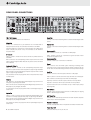
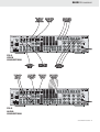
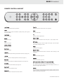
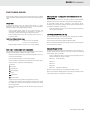
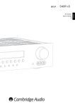
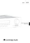
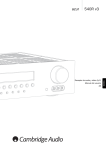
INTRODUCTION
CONTENTS
Thank you for purchasing this Cambridge Audio 540R AV receiver. It
represents Cambridge Audio's first move into the exciting world of multichannel sound. It stems from a tradition of over 30 years of producing
stereo amplifiers and holds true to the Cambridge philosophy of
excellent performance at the best possible price. We hope that you will
enjoy many years of happy and rewarding ownership.
Introduction................................................................................................. 2
About this AV receiver
Rear panel connections…………………………………………………... .................4
The 540R is designed to maximise multi-channel performance without
compromising on stereo reproduction. As such, the six, 80W discrete
amplifiers are kept as separate as possible from the processing and
input stages. An oversized power supply ensures that the 540R can
maintain a high power output into difficult electrical loads to ensure a
powerful and effortless sound.
A full range of Digital and analogue inputs are fitted to the 540R. The
four Digital inputs allow for the connection of suitably equipped DVD
players, satellite boxes and games consoles for decoding into digital
surround formats. In addition, there are conventional stereo inputs for
CD players and the like to ensure the best possible stereo reproduction.
The 540R is also capable of decoding your stereo sources in Dolby Pro
Logic® II (Pro Logic is a registered trademark of Dolby Laboratories), for
a convincing and effective surround experience from a stereo source.
This ensures sources such as analogue televisions and VCR's can make
full use of the 540R's surround capabilities.
In addition to the stereo analogue input, the 540R also carries a sevenchannel analogue input. This feature allows for the connection of a DVD
Audio or SACD equipped player to the 540R. This means that the 540R
is fully equipped to make the most of these exciting new music formats.
As well as the full complement of audio inputs, the 540R also performs
Composite, S-Video and Component Video switching. This means that
the 540R can be used as a hub to carry video signals in addition to the
audio ones. For example, this would enable two Component Video
equipped items to be connected to a single component input on your
television or monitor, meaning more items can be connected to fewer
high quality inputs on your television.
Last, but by no means least, is the fitment of pre-outs to the 540R. This
means that an existing stereo amp can be retained to drive the front
channels or indeed every channel can be driven by a separate power
amplifier and the 540R simply used as a processor and pre-amp. This
feature allows for the retention of existing quality stereo amps and
allows for a degree of additional upgrading.
Now we invite you to sit back, relax and enjoy!
Matthew Bramble
Technical Director
2 azur 540R AV receiver
Contents.......................................................................................................2
Important safety instructions..................................................................... 3
Speaker connection and placement……………………………………….…........ 5
Connecting video and audio source equipment………….…..................... 6
Front panel controls……………………………………………………….……............ ..8
Remote control handset……………………………………………………............... 9
Operation…………………………………………………………………………............... 10
Troubleshooting…………………………………………………………………...........… 12
Technical Specifications………………………………………………………………....12
Limited warranty....................................................................................... 13
540R AV receiver
IMPORTANT SAFETY INSTRUCTIONS
Read and follow instructions - All the safety and operation instructions
should be read before use.
Retain instructions - These instructions should be retained for future
reference.
Lightning - For added protection during a thunderstorm, or when it is left
unattended and unused for long period of time, unplug the 540R from
the wall outlet and disconnect the antenna or cable system. This will
prevent damage to the 540R from lightning and power-line surges.
Heed warnings - Comply with all warnings on the 540R and in the
manual.
Heat dispersion - Leave at least 10 cm of space between the top, back
and sides of the 540R and the wall or other components for proper
ventilation.
Cleaning - Unplug the 540R from the wall outlet before cleaning. Do not
use liquid cleaners or aerosol cleaners. Use a damp cloth for cleaning.
Notes on use
Grounding and polarisation - The 540R may be equipped with a
polarised alternating current line plug (a plug having one blade wider
than the other). This plug will fit into the power outlet only one way. This
is a safety feature. If you are unable to insert the plug fully into the
outlet, try reversing the plug. If the plug should still fail to fit, contact your
electrician to replace your obsolete outlet. Do not defeat the safety
purpose of the polarised plug. (North America Only)
Overloading - Do not overload wall outlets or extension cord as this can
result in a risk of fire or electric shock. Overloaded AC outlets, extension
cords, frayed power cords, damaged or cracked wire insulation, and
broken plugs are dangerous. They may result in a shock or fire hazard.
Power sources - The 540R should be operated only from the type of
power source indicated on the marking label. If you are not sure of the
type of power-supply to your home, consult your product dealer or local
Power Company.
Accessories - Do not place the 540R on an unstable
surface or shelf. The amp may fall, causing serious
injury to a child or adult as well as serious damage
to the product.
Outdoor antenna grounding - If an outside antenna or cable system is
connected to the product, be sure the antenna or cable system is
grounded so as to provide some protection against voltage surges and
built-up static charges. Section 810 of the National Electrical Code,
ANSI/NIPA No. 70-1984 (section 54 of Canadian Electrical Code, Part 1)
provides information with respect to proper grounding of the mast and
supporting structure, grounding of the lead-in wire to an antennadischarge unit, size of grounding conductors, location of antennadischarge unit, connection to grounding electrodes, and requirements
for the grounding electrode.
Power cord protection - Your power supply cord should be placed so that
the power lead is not likely to be walked on or pinched by items placed
upon or against them, paying particular attention to cords at Wall plugs
and where the power lead exits from the 540R.
Contact the service department should any of these conditions occur:
When the power-supply cord or plug is damaged.
If liquid has been spilled, or objects have fallen into the amp.
If the 540R has been exposed to rain or water.
If the 540R does not operate normally after following the operation
instructions, adjust only those controls that are covered by the operation
instructions.
If the amp has been dropped or damaged in any way.
When the amp exhibits a distinct negative change in performance.
Servicing - Do not attempt to service the 540R yourself as removing
cover may expose you to dangerous voltages or other hazards. Refer all
servicing through your dealer to qualified service personnel.
Avoid high temperatures, allow for sufficient heat dispersion when
installed on a rack.
Handle the power cord carefully. Hold the plug when unplugging the
cord.
Keep the 540R free from moisture, water and dust.
Unplug the power cord when not using the 540R for long periods of time.
Do not obstruct the ventilation holes.
Do not let foreign objects, or liquids to get into the 540R.
Never disassemble or modify the 540R.
IMPORTANT
If the 540R is run at a very high level, a sensor will detect a temperature
rise and show "PROTECTION OVERLOAD" on the display. The 540R will
then go into stand-b
by. It cannot be switched on again until the
temperature has fallen to a more normal level
Plug fitting instructions (UK only)
The cord supplied with the 540R is factory fitted with a 13Amp mains
plug fitted with a 13Amp fuse inside. If it is necessary to change the
fuse, it is important that a 13Amp one is used. If the plug needs to be
changed because it is not suitable for your socket, or becomes
damaged, it should be cut off and an appropriate plug fitted following
the wiring instructions below. The plug must then be disposed of safely,
as insertion into a 13Amp socket is likely to cause an electrical hazard.
Should it be necessary to fit a 3-pin BS mains plug to the power cord the
wires should be fitted as shown in this diagram. The colours of the wires
in the mains lead of the 540R may not correspond with the coloured
markings identifying the terminals in your plug. Connect them as
follows:The wire which is coloured BLUE must
be connected to the terminal which is
marked with the letter 'N' or coloured
BLACK.
The wire which is coloured BROWN
must be connected to the terminal
which is marked with the letter 'L' or
coloured RED
The wire which is coloured
GREEN/YELLOW must be connected to
the terminal which is marked with the
letter 'E' or coloured GREEN.
If your model does not have an earth wire, then disregard this
instruction.
Attachments - Do not use attachments not recommended by your dealer
as they may cause harm to the 540R.
azur 540R AV receiver 3
REAR PANEL CONNECTIONS
FM / AM antenna
Coax Out
All tuner antenna connections are made here.
Connect to an external recording device to record selected digital audio
source.
Video out
S-Video out - Connect this to your television via an S-Video cable to
display the picture of any unit connected via S-Video to the 540R.
Composite Video out - Connect this to your television via an RCA phono
cable to display the picture of any unit connected to the 540R via
composite video.
Optical Out
Connect to an external recording device to record selected digital audio
source.
Component in
DVD - Connect to the Cr, Cb, Y terminals of a DVD player.
S-V
Video in
Video 1 / Video 2 - These can be used to connect any S-Video source to
the 540R.
DVD - Connect to the corresponding S-Video output terminal of a DVD
player to play through the 540R. Note that any source can be connected
here if desired.
Video - Connect to the Cr, Cb, Y terminals of a games console or other
component equipped source.
Component Out
Connect to the Pr, Pb, Y terminals on a Television.
Reset
Composite Video in
Video 1 / Video 2 - Connect to the corresponding Composite output
terminal of a piece of video source equipment to play through the 540R.
DVD - Connect to the corresponding Composite output terminal of a DVD
player to play through the 540R.
This is used to reset the whole system including all existing saved
information. Insert a paper clip and hold for approx 3 seconds. The unit
will be reset and all saved settings will return to factory default settings.
Audio In
CD/Aux - Connect to the line output terminals of a CD player.
It is possible to connect any equipment with a Composite video output
to these inputs.
Video 1 /Video 2 - Connect to the line output terminals of a video player.
DVD - Connect to the line output terminals of a DVD player.
Coax in
Tape Play - Connect to the line output terminals on the Tape Deck.
CD - Connect to the corresponding Coaxial Digital output terminal of a
CD player to play throught the 540R.
Tape Rec - Connect to the line input terminals on the Tape Deck.
DVD - Connect to the corresponding Coaxial Digital output terminal of a
DVD player to play throught the 540R.
Any line level source can be connected to any of these inputs (except
Tape Play/Rec).
It is possible to connect any equipment with a coaxial digital output to
these inputs.
6.1 Direct In
Optical in
Video 1 / Video 2 - Connect to the corresponding Optical Digital output
terminal of a suitably equipped video player to play through the 540R.
DVD - Connect to the corresponding Optical Digital output terminal of a
DVD player to play through the 540R.
It is possible to connect any equipment with an Optical Digital output to
these inputs.
Connect to the 7 channel output terminals of a DVD player for playing
DVD-A or SACD through the 540R.
6.1 Direct Out
Connect to the 7 channel input terminals of another amplifier, separate
power amps or active loudspeakers.
Speaker terminals
Connect to loudspeakers with an impedance of between 4 and 8 ohms.
Power On / off
4 azur 540R AV receiver
Press this switch to turn on /off this unit.
540R AV receiver
Connecting loudspeakers
Dipoles diffuse the sound in a slightly different way, and therefore
have different positioning requirements: ideally they should be
mounted to the side of the listener, and up to 15 degrees above
listening height
To avoid damaging the speakers with a sudden high-level signal, be sure
to switch the power off before connecting the speakers.
Check the impedance of your speakers. Connect speakers with an
impedance of between 4 and 8 ohms.
4.
Surround centre speaker - Required for enjoying Dolby® Digital EX
(Dolby is a registered trademark of Dolby Laboroatories) or DTS®-ES
audio (Under license from Digital Theater, System, In, or DTS (BVI)
Limited). Improves the quality of sound effects by filling the gap
between the surround left and rear right speakers.
5.
Subwoofer - The location of any dedicated subwoofer will greatly
effect the quantity and also the quality of the low frequencies.
Please see dedicated subwoofer manual for detailed positioning
information.
The 540R's red speaker terminals are the + (positive) terminals and the
black terminals are the - (negative) terminals.
The diagram below shows how loudspeaker connections are made.
Please note that all connections are made via loudspeaker cable except
the subwoofer which is connected via a standard RCA phono cable.
EXPERIMENT !!
REMEMBER - IF IT SOUNDS RIGHT TO YOU, IT IS RIGHT !!
To surround To surround
right speaker left speaker
To subwoofer
To front left
speaker
To surround
centre speaker
To front right
speaker
To front centre
speaker
Notes on loudspeaker placement
FM antenna
1.
If you live reasonably close to a transmitter and want to use the provided
lead-type FM antenna, connect to the "FM 75 ohm" socket, extend the
lead and attach it to a window frame or wall with thumbtacks, or move
around the room, where reception is best
2.
3.
Front left and right loudspeakers - These should be placed
equidistant to the left and right of your screen far enough apart to
ensure good stereo imaging. If they are too far apart or too close
to the corners of the room they will sound distracting and distant.
It may be desirable to experiment with the 'toe-in' of the units
(angling them towards the listening position) to optimise the front
speaker soundstage and imaging.
Centre channel Loudspeakers - Ideally your centre channel
loudspeaker needs to be positioned directly above or below your
screen, facing the listening position.
Surround left and right Loudspeakers - If you are using normal hi-fi
loudspeakers as your surrounds they should be situated roughly at
listening height and facing into the listening position. It is
suggested that they are wall mounted or alternatively placed on
suitable speaker stands.
Bipolar-type surround speakers can be set up in much the same
way as standard 'monopole' types, so try positioning around
listening height and angle toward the listener
In an area where FM signals are weak, it may be necessary to use a 75
ohm unbalanced-type outdoor FM antenna.
AM loop antenna
The high performance AM loop antenna provided with the receiver is
sufficient for good reception in most areas.
Connect the loop antenna's wires to the AM antenna terminals.
Place the antenna on a shelf, for example, and move around to obtain
the best reception, place as far away as possible from the entire system,
speaker leads and the power cords, to prevent unwanted noise.
If the AM loop antenna provided does not receive sufficient reception, it
may be necessary to use an outdoor AM antenna.
azur 540R AV receiver 5
Connecting video source equipment
Connecting audio source equipment
Video connections
Audio source equipment, such as a CD player, can be listened to through
the 540R.
There are three ways in which video connections to the 540R can be
made (only one video connection should be made):
Component - Connect video source equipment’s Component sockets to
the corresponding sockets on the rear of your 540R using Component
cable (3RCA-3RCA)
S-V
Video - Connect video source equipment’s S-Video socket to the
corresponding socket on the rear of your 540R using S-Video cable
(MINIDIN-MINIDIN).
Composite - Connect video source equipment’s Composite socket to the
corresponding socket on the rear of your 540R using phono cable (RCARCA)
For best picture quality we recommend that video connections are made
via Component sockets where possible.
Note - If connecting two pieces of video source equipment to the 540R
simultaneously (eg a VCR and a DVD player) it is recommended that the
same method of video connection is used. By doing this only one input
on the television will be used.
Video connections are shown in fig.1.
Audio connections
There are three basic options for audio connections to the 540R:
Optical - Connect video source equipment’s optical digital output socket
to the corresponding socket on the rear of the 540R using optical cable
(OPT-OPT)
Coaxial - Connect video source equipment’s coaxial digital output socket
to the corresponding socket on the rear of the 540R using 75 Ohm
phono cable (RCA-RCA)
Line level audio - Connect video source equipment’s audio out sockets
to the corresponding sockets on the rear of the 540R using phono cable
(2RCA-2RCA).
If you want to listen to DVD Audio or SACD discs then it will be necessary
to connect your DVD player to the 6.1 Direct In sockets on the rear of the
540R. Connecting a DVD player to these sockets bypasses the 540R
decoder and sends the signal straight to the built in six channel
amplifier.
Audio connections are shown in fig.2.
6 azur 540R AV receiver
Connections are made as audio connections explained in the previous
column.
Note - To record audio source material an external recording unit (eg
Minidisc) should be connected to the digital or analogue outputs on the
rear of the 540R.
540R AV receiver
From video source
S-V
Video out via
Video cable
S-V
(MINIDIN-M
MINIDIN)
From video source
component video out
via component cable
(3RCA-3
3RCA)
From video source
Composite video out
via phono cable
(RCA-R
RCA)
FIG.1
VIDEO
CONNECTIONS
To television
composite video in via
phono cable
RCA)
(RCA-R
From video source
audio out via
phono cable
(2RCA-2
2RCA)
From video source
coaxial out via 75
Ohm phono cable
RCA)
(RCA-R
To television S-V
Video
Video cable
in via S-V
(MINIDIN-M
MINIDIN)
From video source
optical out via
optical cable
(OPT-O
OPT)
To television
component video in
via component cable
3RCA)
(3RCA-3
From video source
6/7 channel out via
phone cables
(6RCA-6
6RCA)
FIG.2
AUDIO
CONNECTIONS
azur 540R AV receiver 7
FRONT PANEL CONTROLS
azur 540R
Standby/On
Video 3 input sockets
Switches the 540R between Standby and On.
Connect an external VCR, Video Camera Recorder, etc. to these sockets
Phones
DVD
Socket for headphones if required.
Press to select DVD source equipment for ouput through the 540R.
Tuning +/-
Video 1
Use to tune FM frequencies.
Press to select video source equipment connected to Video 1 on the rear
panel for output through the 540R.
Mode/Store (for tuner operation)
Press to cycle between tuner modes (see page 10 for full details).
Stereo
Press this button to listen to audio in stereo from the front left and right
loudspeakers only.
Dolby Digital EX
Press this button to listen to a sixth channel when using a 6.1 channel
source.
Video 2
Press to select video source equipment connected to Video 2 on the rear
panel for output through the 540R.
Video 3
Press to select video source equipment connected to Video 3 on the
front panel for output through the 540R.
Tuner FM/AM
Press to select the tuner for output through the 540R.
Dolby Pro Logic II
In tuner mode use this button to switch between FM and AM mode.
If pressed this button will convert a two channel stereo audio input into
simulated 5.1 surround sound.
Tape/MD/CDR
DSP Mode
Press this button when operating a recording device connected to the
540R.
Press this button to choose one of the following surround sound effects:
THEATER, HALL, PASSTHRU, MOVIE, MUSIC or ROOM. These will subtly
effect the sound that you hear.
CD/Aux
Press to select source equipment connected to CD/Aux on the rear
panel for output through the 540R.
Input Mode
Press this button to cycle between analogue, optical and digital inputs.
6.1 Direct
Press to select DVD player connected to the 6.1 Direct in sockets on the
rear panel to listen to DVD-A or SACD discs through the 540R.
8 azur 540R AV receiver
540R AV receiver
REMOTE CONTROL HANDSET
DD EX
DTS ES
Tune +/-
Push to select desired source equipment.
Press to increase or decrease the tuner frequency.
Power
Input
Select
PL II
LFE
Trim
6.1
Direct
Stereo
Dynamic
Sub
On/Off
Input
Mode
Surr
Mode
CH
Select
Tune +
Test
Tone
Vol +
Mute
SPK
Setup
Tune -
Bass
Vol -
+
Delay
FM
AM
Treble
Store
Display
-
Stereo
Mono
APS
Mode
PTY
Input select
Mute
Push this button to switch the 540R to standby mode, push it again to
turn off the 540R.
Press to mute audio.
Input mode
+/-
See previous page.
Press for function adjustments.
Stereo
Bass / Treble
See previous page.
Press for Bass and treble control. Then press +/- key to adjust levels.
PL II
SPK setup
See previous page.
If you are listening to a source in digital or Pro Logic® II you can adjust
your speaker settings from here.
DD EX / DTS ES
See previous page.
Delay
See Delay Time (page 11).
Surr mode
See previous page.
Stereo / Mono
Dynamic
Press to alternate between Stereo and Mono when listening to FM
broadcasts.
Press to access Dynamic Range Compression controls (see page 11),
LFE trim
Press to access Low Frequency Effect controls (see page 11).
Test tone
Press to access Speaker Level Balance Adjustment (see page 11).
Store
See Tuner Operation (page 10).
FM/AM
See Tuner Operation (page 10).
APS search (without RDS) / PTY search (with RDS)
CH select
APS - Allocates and memorises radio stations automatically.
Press to access Channel Select (see page 11).
PTY - Press to view current program type on the display, use Tune +/- to
select the program type you desire.
Sub on/off
Press to turn the subwoofer on/off.
Volume +/-
Display
When listening to source equipment press this button to view input type
(optical, coaxial or analogue). When listening to FM with RDS, press this
button to view station information.
Press to increase or decrease the master volume.
azur 540R AV receiver 9
OPERATION
Playing source material
Storing stations
1.
Switch the Power button on the rear panel to ON.
1.
Press the tuner FM/AM button.
2.
Press Standby button to switch on the 540R.
2.
Select AM or FM by again pressing the Tuner FM/AM button.
3.
Select desired source by pushing the corresponding button on the
540R’s front panel or by using the remote handset.
3.
Press the Mode/Store button two times to select manual tuning
mode, then press the Tuning +/- button to select a frequency
channel you want to preset.
4.
Pressing and holding the Mode/Store button for 5 seconds will
bring up the "MEM" icon.
5.
Use the Tuning+/- buttons to select a preset station. The station
number will be displayed on the screen.
6.
Press the Mode/Store button to memorise.
Note - The Input Mode button is used to select the input mode of
the source equipment, either analogue (ANA), optical (OPT), or
coaxial (COAX) depending on rear panel connection made.
If you are connecting your source equipment digitally (via Optical or
Coaxial connections) then the symbols
should appear on the
display. If UNLOCK appears on the display, the source is either not
connected properly or the source is not switched on.
4.
Play the source, and gradually turn up the volume to the required
level with the Master Volume control.
Tuner operations
How to select preset stations
Press the Mode/Store button on the front panel three times until
PRESET appears on the front panel display, then by pressing the Tuning
+/- buttons you can select a preset channel.
Automatic tuning
1.
Press the Power button, then press the Standby button to On.
2.
Press the Tuner FM/AM button on the front panel or remote
handset.
3.
Use the FM/AM button to select FM or AM.
4.
Press the Mode/Store button on the front panel or the Mode button
on the remote handset to select automatic or manual tuning mode.
5.
Press Tune + and Tune - to select the station you want to listen to
or when a station is tuned in, the tuning process will stop
automatically. (Automatic selection).
6.
Press Tuning + or Tuning - again to select another channel.
Radio Data Systems (RDS)
RDS is a method for the transmission of additional information from
local radio stations. It is only available in FM mode.
RDS will only work if the local broadcasting stations have RDS
transmission and the signal is strong enough.
1.
Press the Display button on the remote, there are functions for PS,
PTY, CT and RT.
2.
For PS (Station Name), press the Display button on the remote until
"PS" appears. The current station name will be shown.
3.
For PTY (Program Type), press the Display button on the remote
until "PTY" appears. The current name type of the program will be
shown.
4.
For CT (Clock - Time), press Display on the front panel until "WAIT"
appears. The current time from Radio Station will be displayed.
Manual tuning
This is for selecting stations, which cannot be tuned automatically
(manual selection).
Note that the Clock - Time will be only transmitted from local radio
station once a minute.
To tune a channel manually, proceed as above, at Step 4 select Manual
and use the Tuning +/- buttons to move up or down the frequencies.
Two FM modes available, stereo and mono - Press the Stereo/Mono
button on the remote control to alternate between Stereo mode and
Mono mode.
If the Display button is pressed, the details of incoming source will be
displayed.
5.
For RT (Radiotext), press the Display button on the remote until "RT"
appears. Some Text messages will be shown.
PTY search (program type search)
1.
Press the PTY button on remote control, "PTY SELECT" will flash on
the display.
2.
Press Tuning + /- to choose the program type, for example NEWS or
SPORT.
3.
Press PTY again once you have chosen the program type.
When the selected type of program is tuned in, it will stop searching,
otherwise, "NO FOUND" will appear.
10 azur 540R AV receiver
540R AV receiver
FINE TUNING SOUND
These functions allow you to fine tune the audio output from the 540R
to get the perfect balance between your home cinema system and your
room.
Channel Select - Loudspeaker level adjustment for 6.1
Direct audio
The channel select button can be used to balance volume between
speakers in 6.1 channel mode when using the 6.1 analogue inputs.
Delay Time
To get the full benefit from your home cinema system it is often
desirable to have output from your surround, rear or centre speakers
delayed, creating a more realistic feeling of space.
Press the SPK Setup button on the remote handset. The
corresponding speaker appears on the display. i.e .C (centre), S
(surround), L/R (front left and right) or BS (back surround)
Press the Delay button to set the time delay and the use the +/buttons to adjust.
Delay time setting adjustable range
®
Dolby Digital mode:
As the Dolby® Digital signal is decoded in the external source,
sometimes, you may have to balance volume between speakers due to
the location of speakers. In this case:
Press the CH Select button on the remote handset and proceed as
per Test Tone instructions.
Low Frequency Effect (LFE mix)
Use this function to fine tune the level of bass outputted by the 540R.
Press the LFE Trim button on the remote handset.
0-15 ms in 5 ms step (S-Delay)
Use the volume keys to adjust between 0dB and -10dB
0-5 ms in 1 ms step (C-Delay)
Note that the LFE function will automatically cancel if the volume button
is not pressed for 5 seconds.
®
Dolby Pro Logic II Mode: 15-30 ms in 1 ms step (S-Delay)
Test Tone - Loudspeaker level adjustment
Dynamic Range Control
The test tone function is useful to adjust the relative volume between
speakers in Dolby® Digital or Dolby® Pro Logic II modes.
By reducing the Dynamic range of the 540R output can be listened to at
a higher volume without bursts of noise. This is useful for watching
movies late at night, for example
Adjust the master volume to the normal listening level (half of max.
volume is recommended)
Press the Dynamic button on remote control repeatedly until the
desired compression range is reached.
Press the Test Tone button on the remote handset.
DRC=0/4
A test tone will be emitted from each speaker each time you press
Test Tone button, looping in the following order:
DRC=1/4
L (front left)
R (front right)
LS (surround left)
RS (surround right)
C (centre)
No Compression
DRC=2/4
DRC=3/4
DRC=4/4
Greatest Compression
Dynamic range compression is not possible with DTS® sources.
Note that the Dynamic Range Control function will automatically cancel
if the volume button is not pressed for 5 seconds.
SUB (subwoofer)
BS (surround back)
Adjust the level of each speaker using the Volume button.
The level of each speaker can be adjusted in 1 dB step from -10dB
to +10dB. Try to ensure that the volume of the tone is the same
from every speaker.
When the setting is finished, press the Test Tone button to stop the
test tone.
azur 540R AV receiver 11
TROUBLESHOOTING
TECHNICAL SPECIFICATIONS
When listening to music in stereo, Left/Right speakers are
reversed.
Power Output
Speakers are wrongly connected.
A low hum or buzz sound can be heard.
THD
100 watts rms per channel,
8 ohms, two channels driven
80 watts rms per channel,
8 ohms all 6 channels driven
<0.006% @1kHz
Power cords or lighting placed near this product.
Crosstalk
Sound is only audible from one channel
Frequency response
<-60dB
20Hz – 20kHz +/- 1dB
One of the input cords is disconnected.
The balance control is set to one side.
Sound cuts off when listening to music or there is no sound
even though power is ON.
Stby power consumption
<2w
Max power consumption
850w
DAC
Speaker impedance is less than prescribed for the 540R.
CS42518 Multi-DAC
CS493263 DSP
Connections
Low bass response.
Speaker polarity (+/-) is reversed.
An unusual hissing noise is heard when listening to the
broadcast in stereo, but not heard when listening in mono.
Audio Inputs
Audio Outputs
A slight noise may be heard because the method used for modulation of
FM stereo broadcasts is different than that used for mono broadcasts.
6 Line Level + Tuner
6.1 Direct Input
6 Amplified Speaker Outputs
6.1 Preamp output
1 Tape record output
Video Inputs
4 Composite, 3 S-Video,
2 Component Video
Video Ouputs
1 Composite, 1 S-Video,
1 Component Video
Digital Inputs
2 Co-Axial, 3 Optical
Broadcast signals are poor or poor antenna placement.
Digital Outputs
1 Co-Axial, 1 Optical
Excessive distortion in speaker output
Dimensions (mm)
Poor reception area.
Weight
Noise is excessive in both stereo and monaural broadcasts.
Poor location and/or direction of the antenna.
Transmitting station is too far away.
Sound is distorted and/or the volume level becomes low
No sound from the rear speakers
Surround On/Off button is set to Off.
Source being played is not recorded or broadcast in surround sound or
stereo.
Cable not connected securely.
No sound from the centre speaker
Surround mode button is not set to Dolby Digital, DTS or Dolby Pro Logic
II.
Remote handset is not working
The batteries are flat.
The remote handset is too far from the receiver or out of the effective
range.
12 azur 540R AV receiver
430 x 100 x 310
9.5kg/20.9lbs
540R AV receiver
LIMITED WARRANTY
Cambridge Audio warrants this product to be free from defects in
materials and workmanship (subject to the terms set forth below).
Cambridge Audio will repair or replace (at Cambridge Audio's option) this
product or any defective parts in this product. Warranty periods may vary
from country to country. If in doubt consult your dealer and ensure that
you retain proof of purchase.
To obtain warranty service, please contact the Cambridge Audio
authorised dealer from which you purchased this product. If your dealer
is not equipped to perform the repair of your Cambridge Audio product,
it can be returned by your dealer to Cambridge Audio or an authorised
Cambridge Audio service agent. You will need to ship this product in
either its original packaging or packaging affording an equal degree of
protection.
Proof of purchase in the form of a bill of sale or receipted invoice, which
is evidence that this product is within the warranty period, must be
presented to obtain warranty service.
This Warranty is invalid if (a) the factory-applied serial number has been
altered or removed from this product or (b) this product was not
purchased from a Cambridge Audio authorised dealer. You may call
Cambridge Audio or your local country Cambridge Audio distributor to
confirm that you have an unaltered serial number and/or you purchased
from a Cambridge Audio authorised dealer.
This Warranty does not cover cosmetic damage or damage due to acts
of God, accident, misuse, abuse, negligence, commercial use, or
modification of, or to any part of, the product. This Warranty does not
cover damage due to improper operation, maintenance or installation,
or attempted repair by anyone other than Cambridge Audio or a
Cambridge Audio dealer, or authorised service agent which is authorised
to do Cambridge Audio warranty work. Any unauthorised repairs will void
this Warranty. This Warranty does not cover products sold AS IS or WITH
ALL FAULTS.
REPAIRS OR REPLACEMENTS AS PROVIDED UNDER THIS WARRANTY
ARE THE EXCLUSIVE REMEDY OF THE CONSUMER. CAMBRIDGE AUDIO
SHALL NOT BE LIABLE FOR ANY INCIDENTAL OR CONSEQUENTIAL
DAMAGES FOR BREACH OF ANY EXPRESS OR IMPLIED WARRANTY IN
THIS PRODUCT. EXCEPT TO THE EXTENT PROHIBITED BY LAW, THIS
WARRANTY IS EXCLUSIVE AND IN LIEU OF ALL OTHER EXPRESS AND
IMPLIED WARRANTIES WHATSOEVER INCLUDING, BUT NOT LIMITED TO,
THE WARRANTY OF MERCHANTABILITY AND FITNESS FOR A PRACTICAL
PURPOSE.
Some countries and US states do not allow the exclusion or limitation of
incidental or consequential damages or implied warranties so the above
exclusions may not apply to you. This Warranty gives you specific legal
rights, and you may have other statutory rights, which vary from state to
state or country to country.
azur 540R AV receiver 13