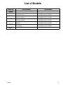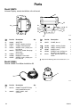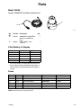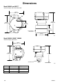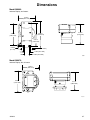
1
Instructions
InformerR In–Line Fluid
Monitoring Package
312013C
For use with paints and coatings with a flashpoint greater than –10°F (–23°C).
Not for use in hazardous locations.
4000 psi (28 MPa, 276 bar) Maximum Working Fluid Pressure
Important Safety Instructions.
Read all warnings and instructions in this manual.
Save these instructions.
See page 2 for Table of Contents and page 3 for List of Models.
Output contacts for batch alarm, batch reset, and user alarm enabled.
Model 288665 shown
GRACO INC. P.O. BOX 1441 MINNEAPOLIS, MN 55440–1441
Copyright 2007, Graco Inc. is registered to I.S. EN ISO 9001
Table of Contents
Table of Contents . . . . . . . . . . . . . . . . . . . . . . . . . . . . . 2
List of Models . . . . . . . . . . . . . . . . . . . . . . . . . . . . . . . . 3
Warnings . . . . . . . . . . . . . . . . . . . . . . . . . . . . . . . . . . . . . 4
Installation . . . . . . . . . . . . . . . . . . . . . . . . . . . . . . . . . . . 6
Typical Installation: Remote Informer Display
and Meter in Non-hazardous Area . . . . . . . . . . . . . 6
Installing Equipment in Hazardous and
Non-hazardous Areas . . . . . . . . . . . . . . . . . . . . . . . 7
Recommended Cables . . . . . . . . . . . . . . . . . . . . . . 7
Flow Meter Installation . . . . . . . . . . . . . . . . . . . . . . . 8
Typical Installation: Remote Informer Display
and Meter in Non-hazardous Area . . . . . . . . . . . . . 9
Typical Installation: Remote Informer Display
in Non-hazardous Area, Meter In
Hazardous Area . . . . . . . . . . . . . . . . . . . . . . . . . . . 10
Display Jumpers and Terminals . . . . . . . . . . . . . . 11
Grounding . . . . . . . . . . . . . . . . . . . . . . . . . . . . . . . . 13
Operation . . . . . . . . . . . . . . . . . . . . . . . . . . . . . . . . . . . .
Pressure Relief Procedure . . . . . . . . . . . . . . . . . .
Flow Meter Operation . . . . . . . . . . . . . . . . . . . . . .
Operating the Informer Display . . . . . . . . . . . . . .
Icons . . . . . . . . . . . . . . . . . . . . . . . . . . . . . . . . . . . . .
Run Mode . . . . . . . . . . . . . . . . . . . . . . . . . . . . . . . .
Alarms . . . . . . . . . . . . . . . . . . . . . . . . . . . . . . . . . . .
Button Functions in Run Mode . . . . . . . . . . . . . . .
Setup Mode . . . . . . . . . . . . . . . . . . . . . . . . . . . . . . .
Button Functions in Setup Mode . . . . . . . . . . . . .
2
13
13
13
14
14
15
15
15
16
16
Setup Parameters . . . . . . . . . . . . . . . . . . . . . . . . .
Alarm Outputs . . . . . . . . . . . . . . . . . . . . . . . . . . . . .
Calibrating the Meter . . . . . . . . . . . . . . . . . . . . . . .
Example 1: Gun Flow Rate Detection . . . . . . . .
Example 2: Batch Dispense Control . . . . . . . . .
Informer Setup Recipe . . . . . . . . . . . . . . . . . . . . . .
17
18
19
20
20
23
Troubleshooting . . . . . . . . . . . . . . . . . . . . . . . . . . . . . 24
Maintenance . . . . . . . . . . . . . . . . . . . . . . . . . . . . . . . . . 26
Battery Replacement . . . . . . . . . . . . . . . . . . . . . . . 26
G3000HR Flow Meter Maintenance . . . . . . . . . . 27
Parts . . . . . . . . . . . . . . . . . . . . . . . . . . . . . . . . . . . . . . . .
Model 288680 . . . . . . . . . . . . . . . . . . . . . . . . . . . . .
Model 288679 . . . . . . . . . . . . . . . . . . . . . . . . . . . . .
Model 288665 . . . . . . . . . . . . . . . . . . . . . . . . . . . . .
Model 288666, 288667 . . . . . . . . . . . . . . . . . . . . .
Model 288668, 288669 . . . . . . . . . . . . . . . . . . . . .
Model 288717 . . . . . . . . . . . . . . . . . . . . . . . . . . . . .
Model 288670 . . . . . . . . . . . . . . . . . . . . . . . . . . . . .
9 Volt Battery for Display . . . . . . . . . . . . . . . . . . . .
Fuses . . . . . . . . . . . . . . . . . . . . . . . . . . . . . . . . . . . .
28
28
29
30
31
32
33
34
35
35
Dimensions . . . . . . . . . . . . . . . . . . . . . . . . . . . . . . . . . . 36
Model 288665, 288666, 288667, 288668 . . . . . . 36
Model 288669, 288670 . . . . . . . . . . . . . . . . . . . . . 37
Technical Data . . . . . . . . . . . . . . . . . . . . . . . . . . . . . . . 38
Graco Standard Warranty . . . . . . . . . . . . . . . . . . . . . 40
Graco Information . . . . . . . . . . . . . . . . . . . . . . . . . . . . 40
312013
List of Models
Model No.
288665
288666
G3000 Flow Meter and Informer Display
Remote Informer Display with 1/2 in. pipe
mounting hardware
G3000 Flow Meter with 50 ft. sensor cable
(P/N 243554) Order kit 243554
288667
Remote Informer Display with 3/4 in. pipe
mounting hardware
G3000 Flow Meter with 50 ft. sensor cable
(P/N 243554) Order kit 243554
288668
Remote Informer Display with 1 in. pipe
mounting hardware
G3000 Flow Meter with 50 ft. sensor cable
(P/N 243554) Order kit 243554
288669
Remote Informer Display with wall mounting
hardware
G3000 Flow Meter with 50 ft. sensor cable
(P/N 243554) Order kit 243554
288670
Remote Informer Display with din rail mounting hardware
G3000 Flow Meter with 50 ft. sensor cable
(P/N 243554) Order kit 243554
288717
G3000HR Flow Meter and Informer Display
312013
Parts Included
Not Included
3
Warnings
The following warnings are for the setup, use, grounding, maintenance, and repair of this equipment. The exclamation point symbol alerts you to a general warning and the hazard symbol refers to procedure–specific risk. Refer
back to these warnings. Additional, product–specific warnings may be found throughout the body of this manual
where applicable.
WARNING
SKIN INJECTION HAZARD
Spray from leaks, or ruptured components can inject fluid into your body and cause extremely serious
injury, including the need for amputation. Splashing fluid in the eyes or on the skin can also cause
serious injury.
D Fluid injected into the skin might look like just a cut, but it is a serious injury. Get immediate surgical treatment.
D Do not stop or deflect fluid leaks with your hand, body, glove, or rag.
D Follow the Pressure Relief Procedure on page 13 whenever you: are instructed to relieve pressure; stop operation; or clean, check, or service the equipment.
D Tighten all the fluid connections before operating the equipment.
D Check the hoses, tubes, and couplings daily. Replace worn, damaged, or loose parts immediately.
FIRE, EXPLOSION, AND ELECTRIC SHOCK HAZARD
Improper grounding, poor air ventilation, open flames, or sparks can cause a hazardous condition and
result in fire or explosion and serious injury.
D Ground the equipment as instructed in Grounding, page 13.
D Never use the flow meter with an electrostatic gun isolation stand.
D Keep liquids away from the electronic sensor device.
D Follow the material supplier recommendations when flushing or servicing the meter.
D Do not service the electronic sensor. Return it to your Graco distributor for service.
D If there is any static sparking while using the equipment, stop spraying immediately. Identify and
correct the problem.
D Keep a fire extinguisher in the work area.
4
312013
EQUIPMENT MISUSE HAZARD
INSTRUCTIONS
Equipment misuse can cause the equipment to rupture, malfunction, or start unexpectedly and result
in serious injury.
D This equipment is for professional use only.
D Read all instruction manuals, tags, and labels before operating the equipment.
D Use the equipment only for its intended purpose. If you are uncertain about usage, call your Graco
distributor.
D Do not alter or modify this equipment. Use only genuine Graco parts and accessories.
D Check the equipment daily. Repair or replace worn or damaged parts immediately.
D Do not exceed the maximum working pressure of the lowest rated system component. This equipment has a 4000 psi (28 MPa, 276 bar) maximum working pressure.
D Use fluids or solvents that are compatible with the equipment wetted parts. See the Technical
Data section of all the equipment manuals. Read the fluid and solvent manufacturer’s warnings.
D Comply with all applicable local, state and national fire, electrical and other safety regulations.
Intrinsic Safety
Intrinsically safe equipment that is installed improperly or connected to non–intrinsically safe equipment will create a a hazardous condition and can cause fire, explosion, or electric shock. Follow local
regulations and the following safety requirements.
D Be sure your installation complies with national, state, and local codes for the installation of an
electrical apparatus in a Class I, Group D, Division I Hazardous Location, including all of the local
safety fire codes, NFPA 33, NEC 500 and 516, and OSHA 1910.107.
D Equipment that comes in contact with the safety barrier’s intrinsically safe terminals must be rated
for Intrinsic Safety. This includes DC voltage meters, ohmmeters, cables, and connections. Remove the unit from the hazardous area when troubleshooting.
D The equipment is intrinsically safe when no external electrical components are connected to it, If a
printer, computer, or other electrical component is connected, it must be used in conjunction with a
safety barrier.
D Do not install equipment approved only for non–hazardous location in a hazardous area. See the
ID label for the intrinsic safety rating for your model.
D Do not substitute system components as this may impair intrinsic safety.
312013
5
Installation
Typical Installation: Remote Informer Display and Meter
(in a non-hazardous area)
A
D
B
C
TI0443A
Fig. 1
Ref.
No.
Part No.
Description
A
B
C
D
948924
239716
*
n
Cable
Meter
Informer
Control Box
*
Informer Display Models
See Informer Display Models Chart for part numbers.
Ref.
No.
Part No.
Description
C
288666
Remote display with 1/2 in.
. . . . . . . . . . . . . . . . . . pipe mounting
C
288667
Remote display with 3/4 in.
. . . . . . . . . . . . . . . . . . pipe mounting
C
288668
Remote display with 1 in. pipe mounting
C
288669
Remote display with wall mounting
C
288670
Remote display with din rail mounting
n Customer supplied component. Includes power supply,
lights, push buttons, relays, valves, cable.
6
312013
Installation
The Informer display is an easy to use means of
collecting fluid data to help reduce fluid waste and
improve processes. The Informer display performs the
following functions:
D
D
D
D
D
D
Monitors flow rate real time
Outputs a signal when flow rate preset is
reached
Tracks batch totals
Outputs a signal when a batch total preset is
reached
Tracks grand totals
Communicates with data reporting software for
process or environmental reporting
The Graco Informer display and fluid flow meter, are
intrinsically safe for Class I; Division 1; Group D hazardous indoor (NEMA 12) locations when installed as
shown in Fig. 4, page 10; “Typical Installation: Remote
Informer Display in Non–hazardous Area, Meter in
Hazardous Area”. Refer to ANSI standards ISARP12.6, NEC Article 504 and the Canadian Electrical
Code Appendix F.
The wiring schematics on pages 9–10 show typical
installations of a flow meter and display. Your installation may consist of different components. Not all the
components shown are supplied by Graco.
D
D
The Informer display can be directly mounted to the
Graco flow meter or remotely mounted from a flow
meter. Informer display models are available for
mounting on a din rail, wall, or pipe.
The Informer display can be battery powered when it is
mounted on the flow meter or externally powered when
it is remotely mounted from the meter.
Installing Equipment in Hazardous
and Non-hazardous Areas
WARNING
FIRE, EXPLOSION, AND ELECTRIC
SHOCK HAZARD
To reduce the risk of fire, explosion, or
electric shock:
D All electrical equipment must only be installed
by a qualified electrician.
D Understand and follow your local code and
safety regulations for hazardous location wiring
of intrinsically safe circuits.
312013
To install a flow meter and display in a nonhazardous area, refer to Fig. 3, page 9.
To install an intrinsically safe flow meter in a
hazardous area and the Informer display in a
non-hazardous area, refer to Fig. 4, page 10.
Do not use more than 50 ft. (15 m) of cable between
the meter and display.
Follow grounding instructions on page 13.
When intrinsically safe barriers are used for hazardous
installations, close attention should be paid to selecting
an appropriate power supply so that valid signals are
applied to the inputs and outputs in accordance with
the technical data on page 38.
Cable shields should be connected to the chassis
ground, not the power supply common, inside the
Informer Display housing. The battery cover screw,
mounting adaptor (51) or sensor housing (31) may be
used for this ground.
Recommended Cables
For power, communication, and I/O
Brand
Alpha
Alpha
Alpha
Alpha Part No.
58612
58613
58616
Type
2 pairs, 22 AWG
3 pairs, 22 AWG
6 pairs, 22 AWG
7
Installation
Flow Meter Installation
Refer to Fig. 2 to locate and install the flow meter,
connectors, and fluid shutoff valves.
D
D
D
Flow volume can only be measured at the
location where the flow meter is installed.
Install a check valve to prevent back-flow. The
arrows on the flow meter and check valve
show the direction of fluid flow.
The shutoff valves allow you to isolate the
meter for service.
Avoid having dust or foreign matter enter the flow
meter by taking the following precautions:
D
D
D
Thoroughly flush the fluid supply lines before
installing the flow meter.
When installing fittings, make sure that no
sealing tape overlaps into the inside of the
pipe.
Install a 100 mesh fluid filter upstream of the
flow meter.
Calibrate the meter as instructed on page 19 before
using the meter for production.
Refer to the Dimensional Drawings on page 37 and
Technical Data on page 38 for equipment specifications.
Informer Display
Fluid Line
Fluid Shutoff Valve
on outlet side
Fig. 2
8
Flow Meter
Check Valve
Fluid Shutoff Valve
on inlet side
9632A
312013
Installation
Informer
013
(288666, 288667, 288669, 288670)
Typical Installation: Remote Informer Display and Meter
in Non-hazardous Area
Fig. 3
312013
9
Installation
Remote Informer Display in Non-hazardous Area,
Meter In Hazardous Area
former
638
(288666, 288667, 288669, 288670)
9636B
Typical Installation:
Fig. 4
10
9636A
312013
Installation
Display Jumpers and Terminals
JP2
The default jumper positions are shown in Table 1. The
hardware configuration of the Informer display can be
customized by changing jumper positions and wiring
the terminals for the desired configuration.
Jumper JP2 determines the source of power for the
Informer display. When pins 1 and 2 are jumpered
together, the Informer display is configured to receive
power from an external DC power source, which must
be connected to terminals 1 and 2 on connector J1.
When pins 2 and 3 are jumpered together (the default
position for Model 288665), the Informer display is
configured to receive power from the internal 9 Volt
battery.
Jumpers
Jumpers JP1, JP2, and JP3 are 3-pin connectors with
2-pin shunt connectors installed. The pins are numbered 1, 2, and 3. See Fig. 5.
JP1
Jumper JP1 determines the meter pulse source. When
pins 1 and 2 are jumpered together, the Informer
display is configured to receive pulses from an external
meter, which must be connected to terminals 3 and 4
on connector J2. When pins 2 and 3 are jumpered
together (the default position for Model 288665), the
Informer display is configured to accept pulses from
the meter it is mounted on. This position minimizes
power consumption for battery operated configurations.
JP3
This jumper is not used. It should be removed or left
on pins 2 and 3.
Table 1
Jumpers
JP1
JP2
JP3
Pins
1–2
Remote meter connection to
pulse input
External power source
Defines
2–3
Display mounted on meter
Internal 9 V battery
Pulse source
Power source
Not used
JP3
F6
123
1 23 4
J1
JP2
1 23 4 5 67 8
123
F1
F2 F5
P1
J2
F4 F3
123
JP1
Fig. 5
312013
Inside Front Cover of Informer Display
TI0049
11
Installation
Terminals
J2 – 1 and 2 Batch Reset
Connector J1 terminals are numbered 1 through 4.
Connector J2 terminals are numbered 1 through 8.
Terminal definitions and typical wiring connections are
shown in figures 3 to 4 on pages 9 to 10.
An external signal applied to this input will reset the
Batch Totalizer to zero if the totalizer is a type t1 or t3,
or it will preset the Batch Totalizer if it is a type t2 (see
setup parameters for details, page 17). Terminal 1 is
the positive connection. The input is internally current
limited. See the Technical Data on page 38 for details
on input signal specification.
J1 – 1 and 2 External Power
External power is supplied to these terminals. Terminal
1 is the positive connection. The external power connection supplies power for the Informer display’s
internal circuitry. See the Technical Data on page 38
for details.
An external power supply is required for operation
when any of the external inputs or outputs described
below are used. This includes: external alarms, external batch reset, remote mounted meter, and networking with a computer. Battery operation can only be
used with the meter mounted option (Model 243312).
If Graco Power Supply 195638 is used:
For North American power connection, select a power
supply cord that fits the following requirements:
D
D
D
D
UL Listed and CSA Certified
18 AWG
Terminated in a molded on plug cap rated
125 V, 15 A
Minimum length of 6 ft (1.8 m)
For European power connection, select a power supply
cord that is internationally harmonized and fits the
following requirements:
D
D
D
D
Marked “<HAR>” 0,75 mm2 minimum
mm2 wire
Rated 300 V
PVC insulated jacket
Molded on plug cap rated 250 V, 10 A
J1 – 3 and 4 RS–485
The Modbus RS–485 communication signals are
connected to these terminals. Terminal 3 is the B
signal and terminal 4 is the A signal. Due to very low
power RS–485 transceivers, the Informer should not
be directly connected to a terminated RS–485 network.
If terminators are present on the network, an isolator/
repeater should be used to isolate the Informer from
the rest of the network. The maximum cable length
that can be connected to the Informer’s RS–485 port is
approximately 1200 feet. Isolator/repeaters may be
used to extend the entire RS–485 network length and
the number of units on the network. Contact Graco
customer service for more information.
12
J2 – 3 and 4 Pulse Input
An external signal applied to this input will increment
the internal pulse counter of the Informer display.
Terminal 3 is the positive connection. The internal
pulse counter is used to increment the Totalizers
viewed by the user. The rate of the Totalizer increments are determined by the setup parameters. The
input is internally current limited. See the Technical
Data on page 38 for details on input signal specification.
J2 – 5 and 6 Batch Alarm
The Batch Alarm output is a signal that is turned on by
the Informer if a target value is set for the Batch Totalizer and the Batch Alarm output is enabled in the setup
parameters. The output is a solid-state device, with
terminal 5 as the positive connection. The output is not
internally current limited so you should ensure that the
output current specification is not exceeded. See the
Technical Data on page 38 for details on output signal
specification.
J2 – 7 and 8 User Alarm
The User Alarm output is a signal that is turned on,
based on the parameters that are configured during
setup of the Informer display. The output is a solidstate device, with terminal 7 as the positive connection. The output is not internally current limited so you
should ensure that the output current specification is
not exceeded. See the Technical Data on page 38 for
details on output signal specification.
312013
Installation
3. Always ground the fluid supply unit, using one of
the following options:
Grounding
a. Mount the meter to a grounded conductive
surface, or
WARNING
FIRE, EXPLOSION, AND ELECTRIC
SHOCK HAZARD
Proper electrical grounding of your
system is essential. For your safety,
read the warning section, FIRE, EXPLOSION, OR ELECTRIC SHOCK HAZARD, on
page 4.
b. Connect the conductive fluid hose to the meter
inlet and outlet, or
c.
Connect a ground wire to the meter’s M6
mounting holes.
4. Never use the flow meter with an electrostatic gun
isolation stand.
NOTE: Numbers in parenthesis in the text refer to the
reference numbers in the figures (Fig.) and in the parts
lists.
35 or 54
1. Follow the instructions in manual 308778 to ground
the Graco flow meter and check its electrical
grounding continuity.
2. Ground the Informer display by connecting the
ground wire (44 or 64) from the screw (35 or 54) to
a true earth ground. See Fig. 6.
44 or 64
Fig. 6
Operation
Pressure Relief Procedure
WARNING
SKIN INJECTION HAZARD
The system pressure must be manually relieved to
prevent the system from starting or spraying accidentally. Fluid under high pressure can be injected
through the skin and cause serious injury. To
reduce the risk of an injury from injection, splashing
fluid, or moving parts, follow the Pressure Relief
Procedure whenever you:
D are instructed to relieve the pressure,
D stop spraying,
D check or service any of the system equipment.
1. Turn off the fluid supply to the meter.
2. Shut off all electrical power to the fluid system.
3. Follow the Pressure Relief Procedure for your fluid
system dispensing device.
312013
Flow Meter Operation
For information on Graco flow meter, part no. 239719,
see manual 308778. Calibrate the meter as instructed
on page 19 before using the meter for production.
WARNING
COMPONENT RUPTURE HAZARD
Do not exceed the maximum working pressure of
your meter or any component or accessory in your
system.
CAUTION
The flow meter gears and bearings can be damaged
if they rotate at too high a speed. To avoid high
speed rotation, open the fluid valve gradually. Do not
over-speed the gear with air or solvent. To prolong
meter life, do not use the meter above its maximum
flow rate.
13
Operation
Operating the Informer Display
Press any button to activate the Informer display (bring it out of “Sleep Mode”).
The Informer has two operation modes: Run Mode (page 15) and Setup Mode (page 16).
Icons
As you move through the various Informer screens, you will notice icons appear at the bottom of the screen. The
icons for Flow Rate, Batch Totalizer, and Maintenance Totalizer also appear on the Informer buttons. The icons
represent various run and setup functions and alarm activation. All of the icons are shown displayed in Fig. 7.
K-Factor
Target
Battery
Reset Button
Flow Rate
Batch Totalizer
Fig. 7
14
Maintenance Totalizer
9658A
312013
Operation
Run Mode
When the Informer display is in Run Mode, the current
flow rate, batch totalizer, maintenance totalizer, and
grand totalizer values can be viewed for the flow meter
the Informer display is connected to.
cc/min
Flow Rate Monitoring Screen
Alarms
There are two ways the Informer display can be used
to notify a user when the Batch Totalizer Target, Main-
tenance Totalizer Target, or the Flow Rate Maximum or
Minimum Thresholds have been reached. There is an
alert on the Informer screen in the form of a flashing
icon when the user is in Run Mode and viewing the
related screen information. For example, the flow rate
icon will flash in the flow rate, Run mode screen when
a threshold value is reached.
Alarm outputs can also be enabled so the Informer
display will send a signal to turn on an external alarm
to signal an alarm condition. This enables the user to
be alerted to an alarm condition regardless of which
Informer screen is being viewed. See Alarm Outputs
on page 18.
Button Functions in Run Mode
Button
Function
Flow Rate:
Press the up arrow button to display the current flow rate. If either the flow rate maximum or the
flow rate minimum threshold values are greater than zero, holding the button down will toggle
the display between the flow rate maximum and the flow rate minimum threshold values entered
in Setup Mode. Refer to D2 and D3 setup parameter information on page 18. The flow rate icon
will flash in this screen when a threshold value is reached.
Batch Totalizer:
Press the down arrow button to display the current batch totalizer. If the batch target value is
greater than zero, holding the button down will display the target value entered in Setup Mode.
Refer to A2 setup parameter information on page 17. The batch totalizer icon will flash in this
screen when the target value is reached.
Reset Batch Totalizer
Pressing the reset button for about one-half second while the batch totalizer is displayed will
either set the totalizer to zero if the totalizer is set to count up or preset the totalizer to the target
value if the totalizer is set to count down.
Maintenance Totalizer:
Press the enter button to display the current maintenance totalizer. If the maintenance target
value is greater than zero, holding the button down will display the target value. The maintenance totalizer icon will flash in this screen when the target value is reached.
Reset Maintenance Totalizer
Pressing the reset button for about one-half second while the maintenance totalizer is displayed
will set the totalizer to zero.
Grand Totalizer:
Press the enter and down arrow buttons simultaneously to display the current grand totalizer.
Enter Setup Mode:
Hold down the enter button, then press the up arrow button to enter Setup Mode.
NOTE: The battery icon
is displayed.
312013
will flash to alert you if a low battery alarm occurs, regardless of which Run Mode screen
15
Operation
Setup Mode
The Setup Mode is used to set parameters for monitoring fluid flow with the Informer display. Setup parameters are
described on page 17.
To enter Setup Mode, hold down the enter button
same button sequence will exit Setup Mode.
, then press the up arrow button
Setup Mode is represented by a letter and number on
the left side of the display, which indicate the current
setup parameter. Setup Mode starts with the A1 (Batch
Totalizer Units).
. While in Setup Mode, the
cc
Batch Totalizer Units Setup Screen
Button Functions in Setup Mode
The function of the buttons in Setup Mode varies, depending on which parameter is being set. See the table below
for the basic function of the buttons while in Setup Mode. See page 17 for a description of each setup parameter
and how to configure them.
NOTE: When setting parameters, the value selected for editing will flash.
Button
Function
Enter and Advance to the Next Parameter:
Use the enter button to enter the current value selected (flashing) and advance to the next
setup parameter.
Scrolling Through Fields:
Use the down arrow button to go to the next field of the current setup parameter.
Field: Each of the following numbers is in a separate field: 0 5 . 5
Scrolling Through Selections:
Use the up arrow button to scroll through the valid selections of the current setup parameter.
Valid Selections: 0 to 9 are valid selections for number fields. L, cc, gal, and oz are
valid selections for units.
Reset Value to Zero:
Press the reset button to zero the entire numerical value.
Exit Setup Mode:
Hold down the enter button, then press the up arrow button to exit Setup Mode.
16
312013
Operation
Setup Parameters
NOTE: If the related alarm output is enabled, the
values set for the Batch Totalizer Target, Maintenance
Totalizer Target, and Flow Rate Maximum and Minimum Thresholds determine when an external alarm
will be signaled. See Alarm Outputs on page 18.
A1 – Batch Totalizer Units
Select liters (L), cubic centimeters (cc), gallons (gal),
or ounces (oz) for units of measure. The default setting
or down
arrow buttons to
is cc. Use the up
A3 – Batch Totalizer Type
Select t1, t2, or t3 for the batch totalizer type. The
default setting is t1, which sets the display to count up
from zero to the target value and automatically reset
when the target is reached.
t1: Count Up, auto reset to zero when target value
is reached.
t2: Count down, auto reset to target value when
counter is zero.
t3: Count up, manual reset.
scroll through the selections. Press the enter
button to enter the selection.
cc
L
cc
gal
oz
b1 – Maintenance Totalizer Units
Follow the same process as setting the A1 parameter.
A2 – Batch Totalizer Target Value
Set a target value for the batch totalizer that will alert a
user in Run Mode, viewing the batch totalizer screen,
that a batch is complete. The default setting is 0.0.
button until the
Repeatedly press the up arrow
desired value appears for the selected digit.
cc
Press the down arrow
digit.
button to move to the next
Continue using the arrow buttons to set each digit until
the entire number is set to the desired value.
Press the enter
312013
b2 – Maintenance Totalizer Target Value
Set a target value for the maintenance totalizer that will
alert a user in Run Mode, viewing the maintenance
totalizer screen, when it is time to do preventative
maintenance on the fluid handling system. Follow the
same process as setting the A2 parameter.
cc
C1 – Grand Totalizer Units
The Grand Totalizer cannot be reset. The reading
shows the total amount of fluid that has passed
through the unit since it was started up. To set the
units, follow the same process as setting the A1 parameter.
cc
NOTE: Press the reset
numerical value.
L
cc
gal
oz
button to zero the entire
cc
button to enter the selection.
17
Operation
D1 – Flow Rate Units
Alarm Outputs
Setting the maximum and minimum flow rate threshold
values will provide an alarm to alert you that the process is out of specification.
The next series of setup parameters allow you to
enable (1) or disable (0) the alarm outputs. If the alarm
outputs are enabled, the Informer display will send a
signal to turn on an external alarm to signal an alarm
condition. The default setting for all the alarms is
disabled (0).
Select liters per minute (L/min), cubic centimeters per
minute (cc/min), or ounces per minute (oz/min) for
units of measure. The default setting is cc/min. Follow
the same process as setting the A1 parameter.
L/min
cc/min
oz/min
F1 – Batch Totalizer Alarm Enable
If enabled (F1=1), the batch alarm output is activated
when the batch totalizer reaches the target (if the
batch totalizer type is count up) or reaches zero (if the
batch totalizer type is count down).
D2 – Flow Rate Maximum Threshold Value
Follow the same process as setting the A2 parameter.
The default setting is 0.
cc/min
D3 – Flow Rate Minimum Threshold Value
Follow the same process as setting the A2 parameter.
The minimum threshold value should be no less than
22 * K-factor. The default setting is 0.
F2 – Diagnostic Alarm Enable
If enabled (F2=1), the user alarm output will activate
when the diagnostic status is a non-zero value. The
diagnostic status will repeatedly flash on the screen in
Run Mode until the fault is corrected.
For example, the display will show E=1 for a diagnostic
status of 1. The following is a list of diagnostic status
codes:
Diagnostic Status Codes
E=1
E1 – K-factor
The K-factor setting is the scale factor for the meter
and is specified in units of cc/pulse. The valid range for
K-factor is 0.010 cc/pulse to 1.000 cc/pulse. The
default setting is 0.120, which is the K-factor for the
meter.
E=2
E=3
E=4
cc
18
Invalid node address: The Modbus
network node address is set outside the
valid range of 1 through 247.
Invalid K-factor: The K-factor is set outside the valid range of 0.010 cc/pulse to
1.000 cc/pulse.
Invalid Batch Totalizer Type: The Batch
Totalizer Type is set to a value other than
t1, t2, or t3.
Invalid Flow Rate Threshold: The Flow
Rate Minimum Threshold value is greater
than the Flow Rate Maximum Threshold
value.
312013
Operation
F3 – Flow Rate Alarm Enable
J1 – Battery Powered Operation
If enabled (F3=1), the user alarm output will activate
when the flow rate is greater than the flow rate maximum threshold value. The user alarm output is also
active if the flow rate is less than the flow rate minimum threshold value for three consecutive samples.
The alarm occurs after three consecutive samples to
avoid alarms when stopping or starting fluid flow.
If J1 is set to 1, which is the default setting, the
Informer display will go into sleep mode after 5 minutes without any activity on the keypad. This helps
conserve on battery power. If J1 is set to 0, the
Informer display will never enter sleep mode so it is
always available to respond to Modbus communications requests and external Batch Reset inputs. When
the J1 parameter is displayed the battery icon will
flash.
Calibrating the Meter
F4 – Maintenance Totalizer Alarm Enable
If enabled (F4=1), the user alarm output will activate
when the maintenance totalizer reaches the target
value.
1. Enter Setup Mode by holding down the enter
button
, then pressing the up arrow button
.
2. Set the Maintenance Totalizer Units [b1] to “cc”.
See page 17.
3. Set the K-factor [E1] value to “1.000”. See
page 18.
4. Hold down the enter button
, then press the up
arrow
button to exit Setup Mode.
F5 – Battery Alarm Enable
If enabled (F5=1), the user alarm output will activate
when the battery voltage falls below the useable limit.
The grand totalizer will be saved to non-volatile
memory.
5. Press the enter button
nance Totalizer value.
to display the Mainte-
6. Reset the Maintenance Totalizer value by pressing
the reset D button for about one-half second.
7. Dispense at least 500 cc of material through the
flow meter into a graduated cylinder or beaker.
8. Read the Maintenance Totalizer value.
9. Calculate the new K-factor (cc/pulse) value by
dividing the measured volume of dispensed
material by the value of the Maintenance Totalizer.
H1 – Station ID
Set the station ID between 1 – 246. The default setting
is 1. The actual modbus address will be <station ID>
+1.
K-factor = dispensed volume / Maintenance
Totalizer.
10. Enter Setup Mode.
11. Set the K-factor [E1] value to the calculated value.
12. Verify calibration by exiting Setup Mode, resetting
the Maintenance Totalizer, dispensing material,
and comparing the volume of the dispensed material with the displayed value of the Maintenance
Totalizer.
312013
19
Operation
Examples
NOTE: In the following examples it is assumed:
D External power supply is used
D Meter-mounted Informer package (243312) is used
D Default K-factor of 0.12 cc/pulse is accurate
D Jumper JP2 is set to position 1–2, all other jumpers
and setup parameters not specifically mentioned in
the example, are assumed to be in the default
position or setting
Example 1: Gun Flow Rate Detection
Example 2: Batch Dispense Control
The informer is used to monitor the flow rate through a
gun. If the gun tip is plugged, the flow is restricted and
the flow rate is reduced. If the gun tip is worn, the flow
rate through the gun is increased.
The Informer is used as a batch dispense controller.
The desired batch volume is entered into the Informer’s batch totalizer target value. Fluid flows through
the pipe until the selected volume is reached and the
flow valve is closed. The process repeats when the
batch reset button is pressed.
A power supply is used to power the Informer and the
alarm light. The Informer is set up with maximum and
minimum flow rate threshold values and the flow alarm
is enabled. The alarm light will turn on whenever the
maximum flow rate threshold is reached or exceeded,
or whenever the flow rate is less than or equal to the
minimum threshold value for more than three seconds.
If the flow rate drops to zero in less than three seconds
(e.g., gun shut off) the alarm light will stay off. Optionally, the Informer’s output can be wired to a PLC
instead of the alarm light, for integration into a control
system.
20
A power supply is used to power the Informer, the
batch complete light, the batch reset push button
signal, the batch alarm control relay, and the flow
valve. The Informer is set up by selecting the batch
totalizer units, target value, selecting the count-up with
manual reset function, and enabling the batch alarm
output. When the batch totalizer reaches the programmed target value, the batch alarm output turns
on, pulling in the control relay. The normally open
contact of the control relay illuminates the “batch
complete” light when the batch alarm is active. The
normally closed contact turns off the fluid valve when
the batch alarm is active.
312013
Operation
Example 1: Gun Flow Rate Detection (continued)
INFORMER SETUP RECIPE Date: ___________
Informer S/N: ____________
Setup
Parameters
Description
A1
Batch Totalizer Units
A2
Batch Totalizer Target Value
A3
Batch Totalizer Type
Setup
Configuration
l, cc, gal, oz
t1
t2
t3
l
cc
gal
oz
t1–Count Up, Auto Reset
t2–Count Down, Auto Reset
t3–Count Up, Manual Reset
B1
Maintenance Totalizer Units
B2
Maintenance Totalizer Target
Value
C1
Grand Totalizer Units
l
cc
gal
oz
D1
Flow Rate Units
l
cc
gal
oz
D2
Flow Rate Maximum Threshold
150
Values
D3
Flow Rate Minimum Threshold
50
Value
E1
K-Factor
F1
Batch Totalizer Alarm Enable
0=No
1=Yes
F2
Diagnostics Alarm Enable
0=No
1=Yes
F3
Flow Rate Enable Alarm
0=No
1=Yes
F4
Maintenance Totalizer Units
0=No
1=Yes
F5
Battery Alarm Enable
0=No
1=Yes
H1
Modbus Node Address
J1
Battery Powered Operation
0=No
1=Yes
TI0441A
Fig. 8
Application Description
Manual or automatic gun application detecting minimum flow (tip plugging or low material flow) and high
flow detection (tip wear or excessive flow).
312013
21
Operation
Example 2: Batch Dispense Control (continued)
INFORMER SETUP RECIPE Date: ___________
Informer S/N: ____________
Setup
Parameters
Description
A1
Batch Totalizer Units
A2
Batch Totalizer Target Value
A3
Batch Totalizer Type
Setup
Configuration
l
cc
gal oz
185.0
t1
t2
t3
t1–Count Up, Auto Reset
t2–Count Down, Auto Reset
t3–Count Up, Manual Reset
B1
Maintenance Totalizer Units
B2
Maintenance Totalizer Target
l
cc
gal oz
Value
C1
Grand Totalizer Units
l
cc
gal oz
D1
Flow Rate Units
l
cc
gal oz
D2
Flow Rate Maximum Threshold
Values
D3
Flow Rate Minimum Threshold
Value
E1
K-Factor
F1
Batch Totalizer Alarm Enable
0=No
1=Yes
F2
Diagnostics Alarm Enable
0=No
1=Yes
F3
Flow Rate Enable Alarm
0=No
1=Yes
F4
Maintenance Totalizer Units
0=No
1=Yes
F5
Battery Alarm Enable
0=No
1=Yes
H1
Modbus Node Address
J1
Battery Powered Operation
0=No
1=Yes
TI0442A
Fig. 9
Application Description
Batch dispense of 185 cc shots for metering PVC.
22
312013
Operation
INFORMER SETUP RECIPE
Date: ___________
Informer S/N: ____________
Setup
Parameters
Description
Setup
A1
Batch Totalizer Units
l
A2
Batch Totalizer Target Value
A3
Batch Totalizer Type
t1
cc
t2
gal
oz
t3
t1–Count Up, Auto Reset
t2–Count Down, Auto Reset
t3–Count Up, Manual Reset
B1
Maintenance Totalizer Units
l
cc
gal
oz
B2
Maintenance Totalizer Target
Value
C1
Grand Totalizer Units
l
cc
gal
oz
D1
Flow Rate Units
l
cc
gal
oz
D2
Flow Rate Maximum Threshold Values
D3
Flow Rate Minimum Threshold Value
E1
K-Factor
F1
Batch Totalizer Alarm Enable
0=No
1=Yes
F2
Diagnostics Alarm Enable
0=No
1=Yes
F3
Flow Rate Enable Alarm
0=No
1=Yes
F4
Maintenance Totalizer Units
0=No
1=Yes
F5
Battery Alarm Enable
0=No
1=Yes
H1
Modbus Node Address
J1
Battery Powered Operation
0=No
1=Yes
Application Description
312013
23
Troubleshooting
WARNING
NOTE: The sensor is not a serviceable part. Replace it
if it is malfunctioning.
SKIN INJECTION HAZARD
To reduce the risk of an injection injury or other
serious injury, follow the Pressure Relief Procedure on page 13 before checking or servicing the
meter assembly.
Problem
Cause
Solution
No flow volume displayed at monitoring unit
Flow volume is too low to measure
Increase flow volume
Fluid is not flowing
See Problem: Fluid is not flowing,
below
Damaged cable
Replace cable; see page 7 for
recommended cables
Improper input voltage to sensor
Make sure input power is 12–24 VDC
Blow F5 fuse
Change fuse; see page 35 for
replacement fuses
Jumper JP1 is in the wrong position
Change jumper position; see page 11
Damaged sensor
Replace sensor
Clogs in fluid line or in meter
Clean fluid line and/or meter; see
manual 308778
Gears worn or damaged
Service meter; see manual 308778
A diagnostic status code is flashing on the Informer display
Setup error
Correct setup; see page 18
Battery icon is flashing
Battery is low
Replace battery; see page 26
Batch and Target symbols are
flashing
Batch totalizer setting has been
reached
Press reset button to clear alarm and
totalizer
Flow rate and Target symbols are
flashing
Flow rate maximum threshold has
been exceeded or flow rate is less
than the flow rate minimum threshold
value for three consecutive samples
Alarm will clear when the flow rate is
within the threshold values
Target and Maintenance symbols
are flashing
Maintenance totalizer has reached
the target value
Press reset button to clear the alarm
and totalizer
Display will not turn on
Dead battery
Replace battery (page 26) or install
external power supply
Blow F1 or F6 fuse
Change fuse; see page 35 for
replacement fuses
Jumper JP2 is in the wrong position
Change jumper position; see page 11
Faulty flow sensor or meter
Meter needs calibration
Replace sensor or meter
Calibrate meter
Meter needs calibration
Calibrate meter
Fluid is not flowing
Inaccurate flow reading
24
312013
Troubleshooting
Problem
Cause
Solution
No signal for alarm situation
Incorrect setup
Correct configuration
Incorrect wiring
Correct wiring
Blown F3 fuse (User Alarm)
Replace fuse; see page 35 for
replacement fuses
Blown F4 fuse (Batch Alarm)
Replace fuse; see page 35 for
replacement fuses
External power is off
Turn on power
Auto reset enabled for batch totalizer
Change to manual reset
Cannot retain setup parameters
Flash memory cycle life exceeded
Replace programmed circuit chip
Display readout faulty
Excessive static discharge
Replace LCD display
Ambient temperature too high
Lower ambient temperature
Keypad failure
Excessive wear
Replace membrane switch
Fuses blown
Short circuit
Check wiring
Excessive load
Replace fuse; see page 35 for
replacement fuses
Incorrect address
Check address configuration
Incorrect communication parameters
Check communication parameters
Incorrect data addresses
Check data addresses
Too much data
Check size of data file
Incorrect cabling
Check cable/wiring
Display is in Sleep Mode
Change Setup parameter J1 to zero
Retry communications
Read the desired parameter with
modbus
Communication failure
Flashing “999999” on the display
Display overflow. The value to be
displayed contains a value greater
than the maximum value that can be
displayed
Short battery life
System not configured for low power
operation
Set jumpers JP1, JP3 to position 2–3.
Setup parameters F1, F2, F3, F4, F5,
J1, should be set to “0” (off)
Network communications should not
be used
Informer is in Manufacturing Test
mode
To exit Manufacturing Test mode,
press the Up, Down, and Enter buttons simultaneously. The Informer
will now be in the Setup mode. Hold
the Enter button, then press the Up
arrow button to exit the Setup mode
Display flashes:
312013
/min
/min
/min
/min
25
Maintenance
Battery Replacement (See Fig. 10)
WARNING
FIRE AND EXPLOSION HAZARD
To reduce the risk of fire or explosion:
D Do not remove or install the battery in a hazardous location.
D The internal (9a and 9b or 16) and external (44
or 64) ground wires for the display must be
correctly connected.
NOTE:
D See page 35 for battery part numbers.
D Numbers in parenthesis in the text refer to the
reference numbers in the figures (Fig.) and in the
parts lists.
D The Grand Totalizer value is stored to non-volatile
memory when the battery low condition first appears. If the battery low icon has been displayed
for a significant amount of time before the battery is
replaced, the flow data since the icon appeared will
be lost. The Grand Totalizer value can be manually
stored to non-volatile memory by entering the setup
mode and exiting setup mode. If the Grand Totalizer is manually stored in this way before changing
the battery, no data will be lost.
Display Assembly Mounted on the Meter
1. Remove the display mounting screws (35) and the
external ground wire (44) from the sensor (31).
Pull the sensor out of the lower housing (11).
2. Remove the screw (43) and disconnect the internal
ground wire (9a) from the sensor (31).
7. Replace the battery (3). The battery must be
installed with the correct polarity.
8. Put the internal ground wire (9b) connector in
place and install the screw (8).
9. Check the condition of the gasket (10) and replace
it if it is damaged.
10. Guide the wire connector (9) through the lower
housing (11) and secure the lower housing to the
upper housing (1) with the screws (12).
11. Plug the connector (9) into the sensor circuit board
receptacle (C).
12. Secure the internal ground wire (9a) to the sensor
(31) with the screw (43).
13. Push the sensor (31) back into the housing (11).
14. Put the external ground wire (44) back in place
and secure the display assembly (A) to the sensor
(31) with the screws (35).
Remotely Mounted Display Assembly
1. Remove the display mounting screws (54) and the
external ground wire (64) from the adapter (51).
2. Remove the screw (63) and disconnect the internal
ground wire (16) from the adapter (51). Pull the
adapter out of the lower housing (11).
3. Remove the four screws (12) and remove the
display assembly lower housing (11).
4. Unplug the removeable terminal blocks from their
receptacles (14, 15).
3. Unplug the connector (9) from the sensor circuit
board by pressing the connector latch (B), then
pulling the connector off the receptacle (C).
5. Move the display assembly (A) to a non-hazardous
location.
4. Move the display assembly (A) to a non-hazardous
location.
6. Remove the one screw (8) that secures the cover
(7) and internal ground wire (16) to the battery (3).
5. Remove the four screws (12) and remove the
display assembly lower housing (11).
7. Replace the battery (3). The battery must be
installed with the correct polarity.
6. Remove the one screw (8) that secures the cover
(7) and internal ground wire (9b) to the battery (3).
8. Put the internal ground wire (16) connector in
place and install the screw (8).
26
312013
Maintenance
14
15
11 REF
A
9
B
C
31 REF
3
9b
9a 43
8 REF
Display Assembly to Mount on Meter
3
7
8
10
11
A
51 REF
1
11
35 or 54
31 or 51
12
3
44 or 64
8 REF
Remote Display Assembly
9631A
Fig. 10
Remotely Mounted Display Assembly (continued)
9. Plug the removable terminal blocks into their
receptacles (14, 15).
10. Check the condition of the gasket (10) and replace
it if it is damaged.
11. Guide the internal ground wire (16) through the
lower housing (11) and secure the lower housing to
the upper housing (1) with the screws (12).
312013
16 63
12. Secure the internal ground wire (16) to the adapter
(51) with the screw (63).
13. Push the adaptor (51) back into the housing (11).
14. Put the external ground wire (64) back in place,
and secure the display assembly to the adapter
(51) with the screws (54).
Flow Meter Maintenance
For flow meter maintenance information, see manual
308778.
27
Parts
Model 288680
Informer Display, for installation on meter (meter not included)
2
1
4
6
14
3
15
7
5
8
10
9
11
12
9630B
Ref.
No.
1
2
3
Part No.
Description
193647
243552
4
5
243551
243549
6
280529
6a
115839
HOUSING, upper display
KIT, membrane switch
BATTERY, 9 volt (See chart
on page 35)
KIT, LCD display
KIT, programmed integrated
circuit chip
KIT, circuit board, display;
includes item 6a
S JUMPER; not shown
28
Qty.
1
1
1
1
1
1
3
Ref.
No.
7
8
Part No.
Description
193650
195853
9
195880
COVER, circuit board
SCREW, mach. phillips pan
hd., M2.5 x 6
ASSEMBLY, cable,
w/ connectors
10
11
12
193649
193648
105333
14
15
115732
115733
GASKET
HOUSING, lower display
SCREW, mach., pan hd.,
M4 x 20
TERMINAL, blocks
TERMINAL, blocks
Qty.
1
6
1
1
1
4
1
1
312013
Parts
Model 288679
Informer Display, for remote installation
2
1
4
6
14
3
15
7
5
10
8
11
12
16
9630A
Ref.
No.
1
2
3
Part No.
Description
193647
243552
4
5
243551
243549
HOUSING, upper display
KIT, membrane switch
BATTERY, 9 volt (See chart
on page 35)
KIT, LCD display
KIT, programmed integrated
circuit chip
KIT, circuit board, display;
includes item 6a
S JUMPER; not shown
COVER, circuit board
6
280529
6a
7
115839
193650
312013
Qty.
1
1
1
1
1
1
Ref.
No.
8
Part No.
Description
195853
10
11
12
193649
193648
105333
14
15
16
115732
115733
196141
SCREW, mach. phillips pan
hd., M2.5 x 6
GASKET
HOUSING, lower display
SCREW, mach., pan hd.,
M4 x 20
TERMINAL, blocks
TERMINAL, blocks
WIRE, ground, internal
Qty.
6
1
1
4
1
1
1
3
1
29
Parts
Model 288665
Informer Display, with Graco G3000 flow meter
42
41
40
34
37
35
38
43
36
32
31
33a
33b
33c
33d
33e
33
33f
33g
33h
Ref.
No.
31
32
33
Part No.
Description
243309
113517
239719
33a
110580
33b
33c
33d
33e
33f
33g
33h
34
*
110588
239718
192383
192387
*
290579
288680
35
195874
SENSOR
O-RING, fluoroelastomer
BODY, gear meter, includes
items 33a–33h
S SCREW, cap, socket hd.,
M6 x 30
S HOUSING, meter upper
S O-RING; PTFE
S GEAR ASSEMBLY
S SHAFT, gear
S PIN, dowel
S HOUSING, meter, lower
S LABEL, identification
DISPLAY, Informer; See
parts on page 28
SCREW, mach., phillips pan
hd., M4 x 8
30
9630A
Qty.
1
1
1
12
1
1
2
2
2
1
1
1
2
*
Ref.
No.
36
Part No.
Description
Qty.
105892
37
38
40Y
41Y
42
115698
195889
195909
195910
195867
43
195853
44
222011
SCREW, mach., pan hd.,
M4 x 40
PLUG, dome
BUSHING, strain relief
LABEL, warning, English
LABEL, warning, French
PAINT SHIELD KIT,
includes 10 shields
SCREW, mach. phillips pan
hd., M2.5 x 6
WIRE, ground, external; not
shown
2
2
2
1
1
1
1
1
Not a replacement part. Order item 33, gear meter
assembly.
Y Replacement Warning labels are available at no cost.
312013
Parts
62
60
55
53
54
56, 57
54
51
52
58
61
9639A
Model 288666
Informer Display, remote installation, 1/2 in. pipe mount
Ref.
No.
51
52
53
54
Part No.
Description
196301
195857
113517
195874
55
288679
56
57
115698
195889
ADAPTER
PLATE, adapter mounting
O-RING, fluoroelastomer
SCREW, mach., phillips pan
hd., M4 x 8
DISPLAY, remote; See page
29 for parts
PLUG, dome
BUSHING, strain relief
Qty.
1
1
1
4
Ref.
No.
58
Part No.
Description
195868
60Y
61Y
62
195909
195910
195867
63
195853
64
222011
CLAMP, cushion, u-bolt, for
1/2 in. pipe
LABEL, warning, English
LABEL, warning, French
PAINT SHIELD KIT,
includes 10 shields
SCREW, mach. phillips pan
hd., M2.5 x 6; not shown
WIRE, ground, external; not
shown
1
2
2
Qty.
2
1
1
1
1
1
Model 288667
Informer Display, remote installation, 3/4 in. pipe mount
Ref.
No.
51
52
53
54
Part No.
Description
196301
195857
113517
195874
ADAPTER
PLATE, adapter mounting
O-RING, fluoroelastomer
SCREW, mach., phillips pan
hd., M4 x 8
DISPLAY, remote; See page
29 for parts
PLUG, dome
BUSHING, strain relief
CLAMP, cushion, u-bolt, for
3/4 in. pipe
55
288679
56
57
58
115698
195889
195869
312013
Qty.
1
1
1
4
Ref.
No.
60Y
61Y
62
Part No.
Description
195909
195910
195867
63
195853
64
222011
LABEL, warning, English
LABEL, warning, French
PAINT SHIELD KIT, includes 10 shields
SCREW, mach. phillips pan
hd., M2.5 x 6; not shown
WIRE, ground, external; not
shown
1
2
2
2
Qty.
1
1
1
1
1
Y Replacement Warning labels are available at no cost.
31
Parts
Model 288668
Informer Display, remote installation, 1 in. pipe mount
See drawing on page 31
Ref.
No.
51
52
53
54
Part No.
Description
196301
195857
113517
195874
55
288679
56
57
115698
195889
ADAPTER
PLATE, adapter mounting
O-RING, fluoroelastomer
SCREW, mach., phillips pan
hd., M4 x 8
DISPLAY, remote; See page
29 for parts
PLUG, dome
BUSHING, strain relief
Qty.
1
1
1
4
Ref.
No.
58
Part No.
Description
195870
60Y
61Y
62
195909
195910
195867
63
195853
64
222011
CLAMP, cushion, u-bolt, for
1 in. pipe
LABEL, warning, English
LABEL, warning, French
PAINT SHIELD KIT,
includes 10 shields
SCREW, mach. phillips pan
hd., M2.5 x 6; not shown
WIRE, ground, external; not
shown
1
2
2
Qty.
2
1
1
1
1
1
Model 288669
Informer Display, remote installation, wall mount
62
55
53
56, 57
54
54
51
60
58
Ref.
No.
51
53
54
Part No.
Description
196301
113517
195874
55
288679
56
57
58
115698
195889
195856
ADAPTER
O-RING, fluoroelastomer
SCREW, mach., phillips pan
hd., M4 x 8
DISPLAY, remote; See page
29 for parts
PLUG, dome
BUSHING, strain relief
BRACKET, wall mount
Qty.
1
1
4
1
2
2
1
Ref.
No.
Part No.
Description
Qty.
60Y
61Y
195909
195910
1
1
62
195867
LABEL, warning, English
LABEL, warning, French;
not shown
SHIELD, paint
63
195853
1
64
222011
SCREW, mach. phillips pan
hd., M2.5 x 6; not shown
WIRE, ground, external; not
shown
1
1
Y Replacement Warning labels are available at no cost.
32
312013
Parts
Model 288717
Informer Display, with Graco G3000HR flow meter
42
41
40
34
37
35
38
43
36
32
31
33a
33b
33c
33d
33e
33
33f
33g
33h
Ref.
No.
31
32
33
Part No.
Description
243309
113517
244291
33a
110580
33b
33c
33d
33e
33f
33g
33h
34
*
110588
244290
197142
192387
*
291643
288680
35
195874
SENSOR
O-RING, fluoroelastomer
BODY, gear meter, includes
items 33a–33h
S SCREW, cap, socket hd.,
M6 x 30
S HOUSING, meter upper
S O-RING; PTFE
S GEAR ASSEMBLY
S SHAFT, gear
S PIN, dowel
S HOUSING, meter, lower
S LABEL, identification
DISPLAY, Informer; See
parts on page 28
SCREW, mach., phillips pan
hd., M4 x 8
312013
9630B
Qty.
1
1
1
12
1
1
2
2
2
1
1
1
2
*
Ref.
No.
36
Part No.
Description
105892
37
38
40Y
41Y
42
115698
195889
195909
195910
195867
43
195853
44
222011
SCREW, mach., pan hd.,
M4 x 40
PLUG, dome
BUSHING, strain relief
LABEL, warning, English
LABEL, warning, French
PAINT SHIELD KIT,
includes 10 shields
SCREW, mach. phillips pan
hd., M2.5 x 6
WIRE, ground, external; not
shown
Qty.
2
2
2
1
1
1
1
1
Not a replacement part. Order item 33, gear meter
assembly.
Y Replacement Warning labels are available at no cost.
33
Parts
Model 288670
Informer Display, remote installation, din rail mount
62
55
59
53
60
56, 57
61
54
51
52
58
Ref.
No.
51
52
53
54
Part No.
Description
196301
195857
113517
195874
55
288679
56
57
58
115698
195889
195875
ADAPTER
PLATE, adapter mounting
O-RING, fluoroelastomer
SCREW, mach., phillips pan
hd., M4 x 8
DISPLAY, remote; See page
29 for parts
PLUG, dome
BUSHING, strain relief
SCREW, mach., phillips pan
hd., M4 x 16
Qty.
1
1
1
2
1
2
2
4
TI0078
Ref.
No.
59
Part No.
Description
Qty.
195871
CLAMP, din rail
1
60Y
61Y
62
63
195909
195910
195867
195853
1
1
1
1
64
222011
LABEL, warning, English
LABEL, warning, French
SHIELD, paint
SCREW, mach. phillips pan
hd., M2.5 x 6; not shown
WIRE, ground, external; not
shown
1
Y Replacement Warning labels are available at no cost.
Model 243554
Remote G3000 Flow Meter Installation Kit
71
72
TI0077
Ref.
No.
71
Part No.
Description
239716
72
948924
G3000 FLOW METER; See
manual 308778 for parts
CABLE ASSY., 50 ft.
(15.24 m)
34
Qty.
1
1
312013
Parts
Model 234106
Remote G3000HR Flow Meter Installation Kit
71
72
TI0077
Ref.
No.
71
Part No.
Description
Qty.
244292
72
948924
G3000HR FLOW METER;
See manual 308778 for
parts
CABLE ASSY., 50 ft.
(15.24 m)
1
1
9 Volt Battery for Display
Brand
Ultralife*
Duracell
Duracell
EverReady
EverReady
*
Part No.
U9VL
MN1604
PC1604
EN22
522
Type
Lithium
Alkaline
Alkaline
Alkaline
Alkaline
An Ultralife battery is shipped with the Informer display in order to replace the Alkaline test battery. A
Lithium battery is recommended for extended battery life.
Fuses
Fuse
F1
F2
F3
F4
F5
F6
Value
0.1 A
0.1 A
0.1 A
0.1 A
0.1 A
0.1 A
Description
External power source
Batch reset input
User alarm output
Batch alarm output
Pulse signal input
Battery power source
Wickman Part No.
3950100044
3950100044
3950100044
3950100044
3950100044
3950100044
Graco Part No.
115838
115838
115838
115838
115838
115838
NOTE: All fuses are fast acting, style TE5.
312013
35
Dimensions
Model 288665 and 288717
Informer Display, with Graco flow meter
4.02 in.
(102.1 mm)
M6
4.90 in.
(124.5 mm)
5.63 in.
(143.0 mm)
1.73 in.
(43.9 mm)
2.16 in.
(54.86 mm)
1/4–18 npt(f)
inlet/outlet
3.35 in.
(85.1) mm
9633A
Model 288666, 288667, 288668
Informer Display, pipe mount
4.02 in.
(102.1 mm)
4.90 in.
(124.5 mm)
See Table
See Table
9639A
Model
Pipe Diameter
Height
288666
0.50 in. (12.7 mm)
5.42 in. (137.7 mm)
288667
0.75 in. (19.1 mm)
5.52 in. (140.2 mm)
288668
1.00 in. (25.4 mm)
5.64 in. (143.3 mm)
36
312013
Dimensions
Model 288669
Informer Display, wall mount
4.02 in.
(102.1 mm)
6.00 in.
(152.4 mm)
4.90 in.
(124.5 mm)
4.90 in.
(124.5 mm)
5.25 in.
(133.4 mm)
0.28 in.
(7.1 mm)
2.30 in.(58.4 mm)
1.50 in.(38.1 mm)
1.06 in.(26.9 mm)
9638A
Model 288670
Informer Display, din rail mount
4.02 in.
(102.1 mm)
4.90 in.
(124.5 mm)
4.21 in.
(106.9 mm)
T10077
312013
37
Technical Data
Display
RS–485 Communication Port
6 digit, 1 inch (25.4 mm) high LCD display
D
Keypad
D
4 button membrane with tactile feedback on 3
buttons
Power Requirements
D
D
D
9 VDC internal battery at 2 mA (display on)
Or 12 to 24 VDC external power supply at
10 mA
Replaceable fuse, reverse polarity protected
Pulse Input
D
D
D
8 VDC at 2.5 mA to 24 VDC at 16 mA
Current sinking or sourcing
1000 pulses/sec. maximum, 50% duty cycle
Control Inputs and Outputs
D
D
D
D
38
Optically isolated, replaceable fuse, reverse
polarity and over-voltage protected
Batch Reset Input
D 8 VDC at 2.5 mA to 24 VDC at 16 mA
D Current sinking or sourcing
D 50 mS pulse width minimum
D Not active while unit is in “Sleep
Mode”–refer to page 39
Batch Alarm Output
D 24 VDC, 150 mA maximum
D Current sinking or sourcing
User Alarm Output
D 24 VDC, 150 mA maximum
D Current sinking or sourcing
Modbus RTU Communication Protocol
(Function 3 and 16)
Not active while unit is in “Sleep
Mode”–refer to page 39
K-Factor Value Range
0.01 to 1.0 cc/pulse
Input, Output, Power, and Communication
Connections
D
D
Removable terminal block
Cable Ports: 2 with strain reliefs, 0.312 in.
(7.9 mm) diameter cable maximum
Environmental
D
D
D
D
D
Operating temperature: 32_ to 140_ F
(0_ to 60_C)
Storage temperature: –67_ to 140_ F
(–55_ to 60_C)
Humidity: 0 to 95%, non-condensing
Display housing meets NEMA 12 requirements
Display housing is solvent resistant
Compliances
Intrinsically safe (Class I, Div. 1, Group D) when
installed as shown in Fig. 4, page 10; “Typical
Installation: Remote Informer Display in Non–
hazardous Area, Meter in Hazardous Area”.
312013
Technical Data
Display Parameters
Display updated in approximately 1/2 sec intervals.
D Grand Totalizer
D Selectable Units (L, gal, cc, oz)
D Count Up
D Backed up to non-volatile memory
D Maximum displayed value: “999999”
D Maximum stored value: 429,496,729.5 cc
(accessible with Modbus)
D Batch Totalizer
D Selectable Units (L, gal, cc, oz)
D Count Up or Down
D Settable Target
D Maximum displayed value: “99999.9”
D Maximum stored value: 429,496,729.5 cc
(accessible with Modbus)
D Auto or Manual Reset
D Alarm when Target value is reached
causes flashing Icon and output active
D Preventative Maintenance Totalizer
D Selectable Units (L, gal, cc, oz)
D Count Up
D Settable Target
D Maximum displayed value: “99999.9”
D Maximum stored value: 429,496,729.5 cc
(accessible with Modbus)
D Manual Reset
D Alarm when Target value is reached
causes flashing Icon and output active
D Flow Rate
Display update time: 1 sec.
312013
Sleep Mode
D
D
To conserve battery power, if no external
power supply is connected, the Informer will
enter Sleep Mode after 5 minutes of no activity
on the front panel push buttons.
The Informer will leave Sleep Mode when flow
is detected.
Software Upgrades
Software upgrades are performed by replacing the
programmable chip on the circuit board.
Model 243312 Meter
See manual 308778 for meter technical data.
39
Graco Standard Warranty
Graco warrants all equipment manufactured by Graco and bearing its name to be free from defects in material and workmanship on
the date of sale to the original purchaser for use. With the exception of any special, extended, or limited warranty published by Graco,
Graco will, for a period of twelve months from the date of sale, repair or replace any part of the equipment determined by Graco to be
defective. This warranty applies only when the equipment is installed, operated and maintained in accordance with Graco’s written
recommendations.
This warranty does not cover, and Graco shall not be liable for general wear and tear, or any malfunction, damage or wear caused by
faulty installation, misapplication, abrasion, corrosion, inadequate or improper maintenance, negligence, accident, tampering, or
substitution of non-Graco component parts. Nor shall Graco be liable for malfunction, damage or wear caused by the incompatibility
of Graco equipment with structures, accessories, equipment or materials not supplied by Graco, or the improper design, manufacture, installation, operation or maintenance of structures, accessories, equipment or materials not supplied by Graco.
This warranty is conditioned upon the prepaid return of the equipment claimed to be defective to an authorized Graco distributor for
verification of the claimed defect. If the claimed defect is verified, Graco will repair or replace free of charge any defective parts. The
equipment will be returned to the original purchaser transportation prepaid. If inspection of the equipment does not disclose any
defect in material or workmanship, repairs will be made at a reasonable charge, which charges may include the costs of parts, labor,
and transportation.
THIS WARRANTY IS EXCLUSIVE, AND IS IN LIEU OF ANY OTHER WARRANTIES, EXPRESS OR IMPLIED, INCLUDING BUT
NOT LIMITED TO WARRANTY OF MERCHANTABILITY OR WARRANTY OF FITNESS FOR A PARTICULAR PURPOSE.
Graco’s sole obligation and buyer’s sole remedy for any breach of warranty shall be as set forth above. The buyer agrees that no
other remedy (including, but not limited to, incidental or consequential damages for lost profits, lost sales, injury to person or property,
or any other incidental or consequential loss) shall be available. Any action for breach of warranty must be brought within two (2)
years of the date of sale.
Graco makes no warranty, and disclaims all implied warranties of merchantability and fitness for a particular purpose in connection
with accessories, equipment, materials or components sold but not manufactured by Graco. These items sold, but not manufactured by Graco (such as electric motors, switches, hose, etc.), are subject to the warranty, if any, of their manufacturer. Graco will
provide purchaser with reasonable assistance in making any claim for breach of these warranties.
In no event will Graco be liable for indirect, incidental, special or consequential damages resulting from Graco supplying equipment
hereunder, or the furnishing, performance, or use of any products or other goods sold hereto, whether due to a breach of contract,
breach of warranty, the negligence of Graco, or otherwise.
FOR GRACO CANADA CUSTOMERS
The parties acknowledge that they have required that the present document, as well as all documents, notices and legal proceedings entered into, given or instituted pursuant hereto or relating directly or indirectly hereto, be drawn up in English. Les parties
reconnaissent avoir convenu que la rédaction du présente document sera en Anglais, ainsi que tous documents, avis et procédures
judiciaires exécutés, donnés ou intentés à la suite de ou en rapport, directement ou indirectement, avec les procedures concernées.
Graco Information
TO PLACE AN ORDER, contact your Graco distributor, or call one of the following numbers
to identify the distributor closest to you:
1–800–328–0211 Toll Free
612–623–6921
612–378–3505 Fax
All written and visual data contained in this document reflects the latest product information available at the time of publication.
Graco reserves the right to make changes at any time without notice.
This manual contains English. MM 312013
Graco Headquarters: Minneapolis
International Offices: Belgium, China, Japan, Korea
www.graco.com
1/2007 Revised 9/2007
40
312013