1
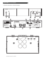
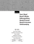
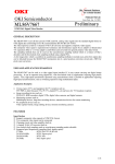
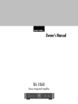
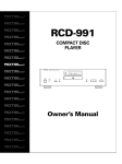
Owner’s Manual
RB-951 MkII
Stereo Power Amplifier
POWER AMPLIFIER RB-951 MkII
CH1
CH2
PROTECTION
POWER
BRIDGED
MONO
CLIPPING
LEVEL
LEVEL
RB-951 MkII Stereo Power Amplifier
English
2
1: Controls, Connections, & Internal Jumpers
POWER AMPLIFIER RB-951 MkII
CH1
CH2
PROTECTION
POWER
BRIDGED
MONO
CLIPPING
LEVEL
1
2
LEVEL
3
6
7
8
12 TRIG IN
CAUTION
4
9
AVIS: RISQUE DE CHOC ELECTRIQUE–NE PAS OUVRIR
TO REDUCE THE RISK
OF FIRE OR ELECTRICAL
SHOCK, DO NOT EXPOSE
THIS EQUIPMENT TO RAIN
OR MOISTURE.
BRIDGED
MONO
10 A
SPEAKERS
CHANNEL 2
CHANNEL 1
INPUT
CH2
CH1
WARNING:
OFF
CH2
NORMAL
STEREO
11
CH1
BRIDGED
SIGNAL OUTPUT
LINK
12
13
AC BREAKER
POWER AMPLIFIER
MODEL NO. RB-951 MkII
POWER CONSUMPTION: 200W
RB-951
P2
P3 P1
123
123
123
S603
S602
S604
123
123
S605
S606
Default Jumper settings shown in illustration.
10
SIGNAL SENSE
STEREO: 4 OHMS MINIMUM
BRIDGED: 8 OHMS MINIMUM
RISK OF ELECTRIC SHOCK
DO NOT OPEN
5
MkII
3
2: Hookup (Stereo or Parallel Mono modes)
RCA OUTPUTS
R
L
12 TRIG IN
CAUTION
SIGNAL SENSE
RISK OF ELECTRIC SHOCK
DO NOT OPEN
10 A
AVIS: RISQUE DE CHOC ELECTRIQUE–NE PAS OUVRIR
INPUT
CH2
CH1
WARNING:
TO REDUCE THE RISK
OF FIRE OR ELECTRICAL
SHOCK, DO NOT EXPOSE
THIS EQUIPMENT TO RAIN
OR MOISTURE.
BRIDGED
MONO
NORMAL
STERO
SPEAKERS
CHANNEL 2
CHANNEL 1
OFF
CH2
BRIDGED
CH1
SIGNAL OUTPUT
LINK
AC BREAKER
POWER AMPLIFIER
MODEL NO. RB-951 MkII
POWER CONSUMPTION: 200W
RB-951
MkII
RB-951 MkII Stereo Power Amplifier
4
3: Hookup (Bridged Mono mode)
RCA OUTPUTS
R
L
12 TRIG IN
CAUTION
SIGNAL SENSE
RISK OF ELECTRIC SHOCK
DO NOT OPEN
10 A
AVIS: RISQUE DE CHOC ELECTRIQUE–NE PAS OUVRIR
INPUT
CH2
CH1
WARNING:
TO REDUCE THE RISK
OF FIRE OR ELECTRICAL
SHOCK, DO NOT EXPOSE
THIS EQUIPMENT TO RAIN
OR MOISTURE.
BRIDGED
MONO
NORMAL
STERO
SPEAKERS
CHANNEL 2
CHANNEL 1
OFF
CH2
POWER AMPLIFIER
MODEL NO. RB-951 MkII
POWER CONSUMPTION: 200W
RB-951
SIGNAL OUTPUT
LINK
BRIDGED
12 TRIG IN
CAUTION
CH1
MkII
SIGNAL SENSE
RISK OF ELECTRIC SHOCK
DO NOT OPEN
10 A
AVIS: RISQUE DE CHOC ELECTRIQUE–NE PAS OUVRIR
INPUT
CH2
CH1
WARNING:
TO REDUCE THE RISK
OF FIRE OR ELECTRICAL
SHOCK, DO NOT EXPOSE
THIS EQUIPMENT TO RAIN
OR MOISTURE.
BRIDGED
MONO
AC BREAKER
NORMAL
STERO
SPEAKERS
CHANNEL 2
CHANNEL 1
OFF
CH2
BRIDGED
CH1
SIGNAL OUTPUT
LINK
AC BREAKER
POWER AMPLIFIER
MODEL NO. RB-951 MkII
POWER CONSUMPTION: 200W
RB-951
MkII
English
5
WARNING: There are no user serviceable parts inside.
Refer all servicing to qualified service personnel.
WARNING: To reduce the risk of fire or electric shock,
do not expose the unit to moisture or water. Do not
allow foreign objects to get into the enclosure. If the
unit is exposed to moisture, or a foreign object gets
into the enclosure, immediately disconnect the power
cord from the wall. Take the unit to a qualified service
person for inspection and necessary repairs.
Read all the instructions before connecting or operating the component. Keep this manual so you can refer to these safety instructions.
Heed all warnings and safety information in these instructions
and on the product itself. Follow all operating instructions.
Clean the enclosure only with a dry cloth or a vacuum cleaner.
You must allow 10 cm or 4 inches of unobstructed clearance around
the unit. Do not place the unit on a bed, sofa, rug, or similar surface that could block the ventilation slots. If the component is placed
in a bookcase or cabinet, there must be ventilation of the cabinet
to allow proper cooling.
Keep the component away from radiators, heat registers, stoves,
or any other appliance that produces heat.
The unit must be connected to a power supply only of the type
and voltage specified on the rear panel of the unit.
Connect the component to the power outlet only with the supplied power supply cable or an exact equivalent. Do not modify
the supplied cable in any way. Do not attempt to defeat grounding and/or polarization provisions. Do not use extension cords.
Do not route the power cord where it will be crushed, pinched,
bent at severe angles, exposed to heat, or damaged in any way.
Pay particular attention to the power cord at the plug and where
it exits the back of the unit.
The power cord should be unplugged from the wall outlet if the
unit is to be left unused for a long period of time.
Immediately stop using the component and have it inspected and/
or serviced by a qualified service agency if:
• The power supply cord or plug has been damaged.
• Objects have fallen or liquid has been spilled into the unit.
• The unit has been exposed to rain.
• The unit shows signs of improper operation
• The unit has been dropped or damaged in any way
Place the unit on a fixed, level surface strong enough to support
its weight. Do not place it on a moveable cart that could tip over.
RB-951 MkII Stereo Power Amplifier
Contents
6
Speakers ................................................ 9
1: Controls, Connections, & Internal Jumpers
2
2: Hookup (Stereo or Parallel Mono modes)
3
3: Hookup (Bridged Mono mode)
4
About Rotel ........................................... 6
Getting Started ...................................... 7
Operating Features
7
A Few Precautions
7
Placement
7
AC Power and Control ............................ 7
Speaker Selection
9
Speaker Wire Selection
9
Polarity and Phasing
9
Speaker Connections
9
Internal Jumper Settings
for Custom Installation ......................... 10
Bypassing the Variable Level Controls
(S603 and S604)
10
Input Sensitivity
(S605 and S606)
10
Selecting Parallel Mono Mode
(S602 and P1/P3)
10
AC Power Input
7
Power Switch and Indicator
7
Troubleshooting .................................... 10
Auto Turn On/Off Mode Selector
7
Front Panel Power Indicator Is Not Lit
10
12V Trigger Input
8
No Sound
10
Circuit Breaker
8
Protection Indicator Is Lit
10
Protection Indicators
8
Specifications ....................................... 11
Stereo/Mono Mode Selection ................. 8
Bridge Switch
and
Front Panel Bridge LED
8
Signal Connections .................................. 8
RCA Inputs
8
Input Level Controls
8
Clipping Indicators
9
Signal Output Link
9
About Rotel
A family whose passionate interest in music
led them to manufacture high fidelity components of uncompromising quality founded Rotel
over 30 years ago. Over the years that passion has remained undiminished and the goal
of providing exceptional value for audiophiles
and music lovers regardless of their budget,
is shared by all Rotel employees.
The engineers work as a close team, listening to, and fine tuning each new product until
it reaches their exacting musical standards.
They are free to choose components from
around the world in order to make that product the best they can. You are likely to find capacitors from the United Kingdom and Germany, semiconductors from Japan or the United
States, and toroidal power transformers manufactured in Rotel’s own factory.
Rotel’s reputation for excellence has been
earned through hundreds of good reviews and
awards from the most respected reviewers in
the industry, who listen to music every day.
Their comments keep the company true to its
goal – the pursuit of equipment that is musical, reliable and affordable.
All of us at Rotel thank you for buying this
product and hope it will bring you many hours
of enjoyment.
7
Getting Started
Thank you for purchasing the Rotel RB-951MkII
Stereo Power Amplifier. When used in a highquality music or home theater system, your Rotel
amplifier will provide years of musical enjoyment.
The RB-951MkII is a sophisticated two-channel power amplifier. Discrete output devices,
a massive power supply with toroidal transformer, premium components, and Rotel’s Balanced Design ensure superb sound quality.
High current capability allows the RB-951MkII
to drive difficult speaker loads with ease.
Placement
Power Switch and Indicator
The RB-951MkII generates heat as part of its
normal operation. The heat sinks and ventilation openings in the amplifier are designed
to dissipate this heat. The ventilation slots in
the top cover must be unobstructed. There
should be 10 cm (4 inches) of clearance around
the chassis, and reasonable airflow through
the installation location, to prevent the amplifier from overheating.
The power switch is located on the left side
of the front panel. To turn the amplifier on (or
to activate either of the optional automatic
power-on modes), push the switch in. The LED
indicator above the switch will light, indicating that the amplifier is turned on. To turn the
amplifier off, push the button again and return it to the out position.
Likewise, remember the weight of the amplifier when you select an installation location.
Make sure that the shelf or cabinet can support its considerable bulk. Again, use common
sense.
Operating Features
• Two-channel Stereo or Bridged Mono operation (back panel switchable)
• Optional Parallel Mono operation for driving low impedance multi-speaker loads in
custom installation applications (requires
resetting internal jumpers).
• User-selectable power on/off configuration:
manual, automatic signal sensing, or controlled by remote 12 volt trigger signal.
• Front panel input level controls
• Protection circuitry with front panel indicators
• Front panel clipping indicators
A Few Precautions
Please read this manual carefully. In addition
to basic installation and operating instructions,
it provides valuable information on various
RB-951MkII system configurations as well as
general information that will help you get optimum performance from your system. Please
contact your authorized Rotel dealer for answers to any questions you might have. In addition, all of us at Rotel welcome your questions and comments.
Save the RB-951MkII shipping carton and all
enclosed packing material for future use. Shipping or moving the RB-951MkII in anything other
than the original packing material may result
in severe damage to your amplifier.
Be sure to keep the original sales receipt. It is
your best record of the date of purchase, which
you will need in the event warranty service is
ever required.
English
AC Power and Control
AC Power Input
The RB-951MkII is supplied with the proper AC
power chord. Use only this cord or an exact
equivalent. Do not use an extension cord. A
heavy duty multi-tap power outlet strip may
be used, but only if it is rated to handle the
current demanded by the RB-951MkII.
Be sure the power switch on the front panel
of the RB-951MkII is turned off. Then, plug one
end of the cord into the AC power connector
on the back panel of the amplifier. Plug the
other end into an appropriate AC outlet.
Your RB-951MkII is configured at the factory
for the proper AC line voltage in the country
where you purchased it (USA: 115 volts/60
Hz , Europe: 230 volts/50 Hz). The AC line
configuration is noted on a label on the back
panel.
NOTE:
Should you move your RB-951MkII to
another country, it is possible to configure your
amplifier for use on a different line voltage.
Do not attempt to perform this conversion yourself. Opening the enclosure of the RB-951MkII
exposes you to dangerous voltages. Consult
a qualified technician or the Rotel factory service department for information.
If you are going to be away from home for
an extended period of time, it is a sensible
precaution to unplug your amplifier.
Auto Turn On/Off Mode
Selector
The RB-951MkII provides three different options
for manual or automatic power on/off operation. These modes are selectable using a threeposition slide switch on the back panel as
follows:
• With the switch in the OFF position,
the amplifier is turned on or off manually
using the front panel power switch. Also
use this mode if you are using a switched
AC outlet to control power to the amplifier.
• With the switch in the SIGNAL SENSING position, the amplifier turns on automatically when a signal is sensed at the
inputs. The amplifier will go into standby
mode five minutes after no signal is present.
The front panel power switch overrides this
function. It must be ON for the signal sensing
to work. Turning the switch OFF cuts power
to the amplifier, regardless of whether or
not a signal is present.
• With the switch in the +12V TRIG.
IN position, the amplifier is turned on
automatically when a 12 volt trigger signal is present at the screw terminals adjacent to the left of the switch. The amplifier
will go into standby mode if the +12 volt
signal is not present. The front panel
POWER SWITCH overrides this function.
It must be ON for the +12V trigger to work.
Turning the switch OFF cuts power to the
amplifier, regardless of whether or not a
trigger signal is present.
RB-951 MkII Stereo Power Amplifier
12V Trigger Input
A pair of screw terminals for connecting the
wires carrying a +12 volt trigger signal to turn
the amplifier on and off, such as might be used
in an elaborate custom installation. To use this
feature the adjacent slide switch must be placed
to the left position (see previous section).
The TRIGGER INPUT accepts any control signal (AC or DC) ranging from 3 volts to 30 volts.
The screw terminals are labeled “+ and –”
Observe proper polarity when connecting the
trigger signal wiring.
Circuit Breaker
A circuit breaker on the rear panel protects
the amplifier’s electrical circuity. Generally, the
circuit breaker will only open under a fault
condition which results in excessive current
draw. To reset the circuit breaker, press the
button. Should it repeatedly open, contact your
authorized Rotel dealer for troubleshooting
assistance.
Protection Indicators
A thermal protection circuit protects the amplifier against potential damage in the event
of extreme or faulty operating conditions. Unlike
many designs, the RB-951MkII’s protection circuit is independent of the audio signal and
has no impact on sonic performance. Instead,
the protection circuit monitors the temperature
of the output devices and shuts down the amplifier if temperatures exceed safe limits.
In addition, the RB-951MkII includes overcurrent
protection which operates only when load impedances drops too low. This protection is independent for the left and right channels with
separate front panel PROTECTION LEDS for
each.
Should a faulty condition arise, the amplifier
will stop playing and the PROTECTION LEDS
on the front panel will light.
If this happens, turn the amplifier off, let it cool
down for several minutes, and attempt to identify and correct the problem. When you turn
the amplifier back on, the protection circuit
will automatically reset and the PROTECTION
LEDS should go out.
8
In most cases, the protection circuitry activates
because of a fault condition such as shorted
speaker wires, or inadequate ventilation leading to an overheating condition. In very rare
cases, highly reactive or extremely low impedance speaker loads could cause the protection circuit to engage.
Stereo/Mono Mode
Selection
The RB-951MkII provides three options for
Stereo or Bridged Mono operation.
• Stereo mode: Conventional 2-channel
stereo operation. Minimum speaker load:
4 ohms.
• Bridged Mono mode: Serial bridged
mode which more than doubles the amplifier power into a single speaker. Minimum speaker load: 8 ohms.
• Parallel Mono mode: A special bridge
mode that allows the amplifier to drive
extremely low impedance speaker loads
such as might be encountered driving multiple speakers in a custom installation.
Minimum speaker load: 2 ohms.
The first two modes are selected using a rear
panel switch. The Parallel Mono mode requires
setting internal jumpers and should only be
done by a qualified technician. See the INTERNAL JUMPER SETTINGS section at the end
of this manual.
Signal Connections
The RB-951MkII provides standard conventional
input connections — unbalanced RCA type
connections as found on nearly all audio
equipment. In addition, there is a pair of SIGNAL OUTPUT LINK connections for passing
the unchanged input signal on to another audio
component.
RCA Inputs
See Figures 2 and 3
These RCA inputs accept audio signals from
preamplifiers or surround sound processors.
Use high quality audio interconnect cables for
best performance.
For Stereo operation, use both inputs. Connect the left channel output of your preamp
to the CH 1 INPUT on the RB-951MkII. Connect the right channel of your preamp to the
CH 2 INPUT. Make sure that the BRIDGE
SWITCH is in the NORMAL STEREO position.
For Bridged Mono operation, use only
the CH1 INPUT. Connect one output channel
of your preamp to the CH 1 INPUT on the
RB-951MkII. Connect the other channel of your
preamp to a second amplifier. Make sure that
the BRIDGE SWITCH selector switch is in the
BRIDGED MONO position.
For Parallel Mono operation, either input may be used. The signal from either will
be sent to all speaker outputs.
Input Level Controls
Bridge Switch
and Front
Panel Bridge LED
A rear panel switch selects Stereo mode or
Bridged Mono mode.
For Stereo mode: Slide the switch to the right,
use both input connectors, and connect one
speaker to each pair of speaker connectors.
The front panel LED will be extinguished.
For Bridged Mono mode: Slide the switch
to the left, use only the CH1 INPUT connection, and connect only one speaker to the two
outer speaker connectors. The front panel LED
will light to indicate Bridged Mono mode.
Two recessed controls on the front panel, one
for each channel, provide input level adjustments. These allow you to adjust the gain of
the amplifier to match other components in an
elaborate system. The CH1 level control
changes the gain of the left channel; the CH2
level control changes the right channel.
To adjust these controls, use a small, flat-blade
screwdriver. Turn the control clockwise to increase gain. Turn counterclockwise to reduce
gain.
NOTE:
These controls may be disabled by resetting an internal jumper.
9
Clipping Indicators
Speaker Wire Selection
Two front panel LEDs (one for each channel)
flash to indicate when the amplifier is “clipping” or being asked to deliver more output
current than it is capable of delivering. Clipping will cause distortion levels to increase.
Use insulated two-conductor stranded wire to
connect the RB-951MkII to the speakers. The
size and quality of the wire can have an audible effect on the performance of the system.
Standard speaker wire will work, but can result in lower output or diminished bass response,
particularly over longer distances. In general,
heavier wire will improve the sound. For best
performance, you may want to consider special high-quality speaker cables. Your authorized Rotel dealer can help in the selection of
appropriate cables for your system.
Occasional brief clipping on the loudest musical passages is acceptable. However, sustained or frequent clipping is one of the most
common causes of speaker damage and should
be avoided.
Should this occur, either reduce the overall gain
of the system by turning down the master volume
control on your preamp. Alternatively, you may
wish to permanently reduce the gain of the
amplifier using the front panel level controls
(see previous section).
Signal Output Link
This pair of RCA connections can be used to
pass the unprocessed input signals to another
audio component, for example to “daisy-chain”
an additional amplifier to drive a second set
of speakers. Any INPUT SIGNAL is also available at these LINK outputs.
Speakers
The RB-951MkII has two pair of speaker connectors, one pair for each channel. These can
be used to connect two loudspeakers in Stereo mode, or to connect one loudspeaker in
Bridged Mono mode.
Speaker Selection
The nominal impedance of the loudspeaker(s)
connected to the RB-951MkII in the various
operating modes should be:
• Stereo mode: minimum 4 ohms
• Bridged Mono mode: minimum 8 ohms
• Parallel Mono mode: minimum 2 ohms
When driving multiple pairs of speakers connected in parallel, the effective impedance the
amplifier sees is cut in half. For example, when
driving two pair of 8 ohm speakers, the amplifier sees a 4 ohm load. When driving multiple speakers in parallel, select speakers with
a nominal impedance of 8 ohms or higher.
Polarity and Phasing
The polarity – the positive/negative orientation of the connections – for every speaker and
amplifier connection must be consistent so all
the speakers will be in phase. If the polarity
of one connection is mistakenly reversed, bass
output will be very weak and stereo imaging
degraded. All wire is marked so you can identify the two conductors. There may be ribs or
a stripe on the insulation of one conductor.
The wire may have clear insulation with different color conductors (copper and silver).
There may be polarity indications printed on
the insulation. Identify the positive and negative conductors and be consistent with every
speaker and amplifier connection.
Speaker Connections
See Figures 2 & 3
The RB-951MkII has one pair of color coded
connections per channel. Labels above the
connectors show the proper connections for
Stereo mode. Labels below show the proper
connections for Bridged Mono mode.
These speaker connectors accept bare wire,
connector lugs, or “banana” type connectors
(except in the European Community countries
where their use is not permitted).
Route the wires from the RB-951MkII to the
speakers. Give yourself enough slack so you
can move the components enough to allow
access to the speaker connectors.
English
If you are using banana plugs, connect them
to the wires and then plug into the backs of
the speaker connectors. The collars of the
speaker connectors should be screwed in all
the way (clockwise).
If you are using terminal lugs, connect them
to the wires. If you are attaching bare wires
directly to the speaker connectors, separate
the wire conductors and strip back the insulation from the end of each conductor. Be careful
not to cut into the wire strands. Unscrew (turn
counterclockwise) the speaker connector collar. Place the connector lug around the shaft,
or insert the bundled wire into the hole in the
shaft. Turn the collars clockwise to clamp the
connector lug or wire firmly in place.
NOTE: Be sure there are no loose wire strands
that could touch adjacent wires or connectors.
In Stereo mode: Connect the left speaker
to the pair of speaker connectors labeled CH1.
Connect the right speaker to the speaker connectors labeled CH2. Follow the labels printed
above the connectors and make sure the
BRIDGE MODE switch is set to the NORMAL
STEREO position. (See Figure 2)
In Bridged Mono mode: Connect the positive terminal of the speaker to the speaker connector labeled BRIDGE +. Connect the negative terminal of the speaker to the speaker connector labeled BRIDGE –. Follow the labels
printed below the connectors and make sure
the BRIDGE switch is set to the BRIDGE MONO
position. (See Figure 3)
In Parallel Mono mode: Connect the speakers in the same fashion as in the Stereo mode.
You can use the connectors for either channel or both – the same output signal is present
at both pair of connectors. (See Figure 2)
RB-951 MkII Stereo Power Amplifier
Internal Jumper Settings
for Custom Installation
(see figure 1)
There are internal jumpers that can be used
to disable the front panel level controls, to select
one of two input sensitivity settings, and to
engage the special Parallel Mono mode for
driving low impedance speaker combinations
in custom installations.
WARNING: Removing the top cover of the amplifier to access the jumpers may expose you
to potentially dangerous voltages. These settings should only be made by a qualified technician. The AC power cord must be removed
from the amplifier before the top cover is removed.
After removing the top cover, the jumper blocks
can be found on the circuit board as shown
in Figure 1. Each jumper block has a printed
identification number. The function, ID numbers, and settings for each jumper block are
provided below. To change the setting, place
the jumper on the appropriate pins as indicated.
Bypassing the Variable Level
Controls (S603 and S604)
The front panel Level Controls allow you to
adjust the input gain for each channel of the
amplifier. These level controls can by bypassed
by changing the jumper position on jumper
blocks S603 (for CH 1) and S604 (for CH2).
To disable the variable level controls:
place a jumper across pins 2 and 3 on jumper
block S603 and across pins 1 and 2 on jumper
block S604.
To enable the variable level controls:
place a jumper across pins 1 and 2 on jumper
block S603 and across pins 2 and 3 on jumper
block S604.
10
Input Sensitivity
(S605 and S606)
Troubleshooting
Jumper blocks S605 and S606 are used to
set the input sensitivity of the amplifier.
Most difficulties in audio systems are the result of poor or wrong connections, or improper
control settings. If you encounter problems,
isolate the area of the difficulty, check the control
settings, determine the cause of the fault and
make the necessary changes. If you are unable to get sound from the RB-951MkII, refer
to the suggestions for the following conditions:
For high sensitivity (0.775v input for
rated power): place the jumpers across pins
1 and 2 on jumper blocks S605 and S606.
For low sensitivity (1.5v input for rated
power): place the jumpers across pins 2 and
3 on jumper blocks S605 and S606.
Selecting Parallel Mono Mode
(S602 and P1/P3)
As described earlier in this manual, the two
most common operating configurations for the
RB-951MkII (Stereo mode and Bridged Mono
mode) are selectable with a back panel switch
and require no internal changes.
The third configuration, Parallel Mono mode,
allows both channels of the amplifier to be combined in parallel. This mode is useful for driving a low impedance speaker load such as
driving multiple speakers in a custom installation.
This Parallel Mono mode can be selected only
by setting internal jumpers (jumper block S602)
and changing a buss wire connection (connectors P1and P2).
NOTE: it is essential that Parallel Mono mode
not be engaged at the same time as Stereo
mode. This will blow the internal rail fuses.
Make sure that you follow all of the instructions below carefully.
To convert to Parallel Mono mode:
1. Place the jumper across pins 1 and 2 on
jumper block S602.
2. Locate the buss wire linking the P2 connector
to the P3 connector. Remove the wire from
P3 and move it to the adjacent P1 connector.
For Parallel Mono mode, the buss wire must
link P2 to P1.
To return to normal configuration (Stereo or Bridged Mono modes):
1. Place the jumper across pins 2 and 3 on
jumper block S602.
2. Locate the buss wire linking the P2 connector
to the P1 connector. Remove the wire from
P1 and move it to the adjacent P3 connector.
For normal mode, the buss wire must link
P2 to P3.
Front Panel Power Indicator Is
Not Lit
No main power to the RB-951MkII. Check AC
power connections at the amplifier and the
AC outlet. Check the front panel power switch.
Make sure that it is set to the ON position. If
using signal sensing auto power-on, make sure
that a signal is present at the inputs. If using
12V trigger power-on, make sure that a trigger signal is present at rear panel screw terminals.
No Sound
If the amp is getting AC power, but is producing
no sound, check the PROTECTION INDICATORS on the front panel. If lit, see below. If
not, check all of your connections and control settings on associated components. Make
sure that your input connections and speaker
connections match your selected stereo/mono
configuration.
Protection Indicator Is Lit
The front panel PROTECTION INDICATORS
light when the RB-951MkII protection circuits
have shut off the amplifier. Typically, this occurs only when the ventilation openings are
blocked, when there is faulty speaker wiring,
or after a period of extreme use. Turn off the
system and wait for the amp to cool. Then push
the front panel power switch in and out to reset the protection devices. If the problem is not
corrected or reoccurs, there is a problem with
the system or the amplifier itself.
English
11
Specifications
Continuous Power Output Stereo Mode
(20-20 kHz, < 0.03% THD)
50 watts/ch into 8 ohms
Continuous Power Output Bridged Mono
Mode (20-20 kHz, < 0.1% THD)
150 watts/ch into 8 ohms
Total Harmonic Distortion
(20Hz-20kHz, 8 ohms)
< 0.03%
Intermodulation Distortion
(60 Hz : 7 kHz, 4:1)
< 0.03%
Frequency Response (±1 dB)
15Hz-100kHz
Damping Factor (20-20,000 Hz, 8 ohms)
280
Speaker Impedance (combined load)
Stereo mode: 4 ohms minimum
Bridged Mono mode: 8 ohms minimum
Parallel Mono mode: 2 ohms minimum
Signal to Noise Ratio (IHF A network)
116 dB
Input Impedance
32 k Ohms
Input Sensitivity
1.5 volt (low setting)
0.775 volt (high setting)
Auto Turn On Threshold Level (if activated)
10 mV input signal
Auto Turn Off Delay Time (if activated)
5 minutes with no signal
Power Requirements
USA: 115 Volts, 60 Hz
Europe: 230 Volts, 50 Hz
Power Consumption
200 Watts
Dimensions (W x H x D)
440 x 92 x 334 mm
173/8 x 35/8 x 131/4 in
Weight (net)
6.8 kg, 15 lb.
All specifications are accurate at the time of printing.
Rotel reserves the right to make improvements
without notice.
The Rotel Co. Ltd.
10-10 Shinsen-Cho
Shibuya-Ku
Tokyo 150-0045
Japan
Phone: +81 3-5458-5325
Fax: +81 3-5458-5310
Rotel of America
54 Concord Street
North Reading, MA 01864-2699
USA
Phone: +1 978-664-3820
Fax: +1 978-664-4109
Rotel Europe
Meadow Road
Worthing, West Sussex BN11 2RX
England
Phone: +44 (0)1903 524 813
Fax: +44 (0)1903 524 831
Rotel Deutschland
Kleine Heide 12
D-33790 Halle/Westf.
Germany
Phone: +49 05201-87170
Fax: +49 05201-73370
082 OMRB-951MkII 113099