1
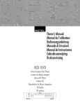
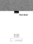
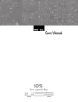
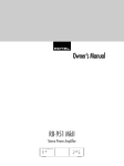
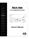
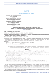
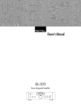
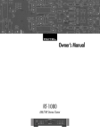
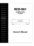
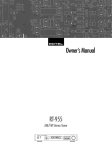
Owner’s Manual
Manuel d’utilisation
Bedienungsanleitung
Manuale di Istruzioni
Manual de Instrucciones
Gebruiksaanwijzing
RB-1050
Stereo Power Amplifier
Amplificateur De Puissance Stéréo
Stereo-Endstufe
Amplificatore di Potenza
Etapa de Potencia Estereofónica
Stereo Eindversterker
POWER AMPLIFIER RB1050
POWER
CH-2 LEVEL
CH-1 LEVEL
CH-1
CH-2
CLIPPING PROTECTION CLIPPING
2
CAUTION
RISK OF ELECTRIC SHOCK
DO NOT OPEN
CAUTION: T O REDUCE THE RISK OF ELECTRIC SHOCK, DO
NOT REMOVE COVER. NO USER-SERVICEABLE PARTS INSIDE
REFER SERVICING TO QUALIFIED SERVICE PERSONNEL.
APPLICABLE FOR USA, CANADA OR WHERE
APPROVED FOR THE USAGE
CAUTION: TO PREVENT ELECTRIC SHOCK, MATCH WIDE BLADE
OF PLUG TO WIDE SLOT. INSERT FULLY.
ATTENTION: POUR EVITER LES CHOCS ELECTRIQUES,
INTRODUIRE LA LAME LA PLUS LARGE DE LA FICHE
DANS LA BORNE CORRESPONDANTE DE LA PRISE ET
POUSSER JUSQU AU FOND.
English
3
Figure 1: Controls and Connections
Commandes et branchements
Bedienelemente und Anschlüsse
Controlli e collegamenti
Controles y Conexiones
De bedieningsorganen en aansluitingen
4
5
4
POWER AMPLIFIER RB-1050
PROTECTION
CH-2
CLIPPING
CH-2 LEVEL
CH-1 LEVEL
CH-1
CLIPPING
POWER
3
1
2
3
10A
CAUTION
SPEAKER IMPEDANCE
RISK OF ELECTRIC SHOCK
DO NOT OPEN
4 OHMS MINIMUM
12V TRIGGER
12V TRIG.
OFF
WARNING:SHOCK HAZZARD–DO NOT OPEN
AVIS:RISQUE DE CHOC'ELECTRIQUE–NE PAS OUVRIR
WARNING: TO REDUCE THE RISK
AC BREAKER
SPEAKERS
INPUT
CH 2
CH 1
OUT
CHANNEL 2
CHANNEL 1
RIGHT
LEFT
IN
SIGNAL SENSE
CH 2
CH 1
OF FIRE OR ELECTRICAL SHOCK,
DO NOT EXPOSE THIS EQUIPMENT
TO RAIN OR MOISTURE.
POWER AMPLIFIER
MODEL NO. RB-1050
POWER CONSUMPTION: 250W
SIGNAL OUTPUT
LINK
SERIAL NO.
6
7
8
9
10
11
12
Figure 2: Preamp Input and Speaker Output Connections
Entrée préamplificateur et sorties enceintes acoustiques
Anschlußdiagramm (Cinch-Eingänge und Lautsprecher)
Collegamenti di ingresso dal preamplificatore e delle uscite dei diffusori
Conexiones para la Señal de Entrada y Salidas para la Conexión de las Cajas
De aansluitingen naar de voorversterker en luidsprekerverbindingen
PREAMPLIFIER
PREAMP OUTPUTS
L
R
SPEAKER
SPEAKER
ROTEL RB-1050
10A
CAUTION
SPEAKER IMPEDANCE
RISK OF ELECTRIC SHOCK
DO NOT OPEN
4 OHMS MINIMUM
12V TRIGGER
12V TRIG.
OFF
WARNING:SHOCK HAZZARD–DO NOT OPEN
AVIS:RISQUE DE CHOC'ELECTRIQUE–NE PAS OUVRIR
WARNING: TO REDUCE THE RISK
OF FIRE OR ELECTRICAL SHOCK,
DO NOT EXPOSE THIS EQUIPMENT
TO RAIN OR MOISTURE.
AC BREAKER
SPEAKERS
INPUT
CH 2
CH 1
OUT
CHANNEL 2
CHANNEL 1
RIGHT
LEFT
IN
SIGNAL SENSE
CH 2
CH 1
POWER AMPLIFIER
MODEL NO. RB-1050
POWER CONSUMPTION: 250W
SIGNAL OUTPUT
LINK
SERIAL NO.
RB-1050 Stereo Power Amplifier
4
Contents
About Rotel
Figure 1: Controls and Connections
Figure 2: Preamp Input and Speaker
Output Connections
3
3
About Rotel .......................................... 4
Getting Started ..................................... 4
A Few Precautions
Placement
4
4
AC Power and Control ........................... 5
AC Power Input
Power Switch
and Power Indicator
12V Trigger Mode Selector
5
5
12V Trigger Input and Output
Circuit Breakers
Protection Circuitry
Clipping Indicators
5
5
5
5
5
Input Signal Connections
.................. 6
Front Panel Level Controls
“Signal Output Link” Connectors
6
6
Speaker Connection ............................... 6
Speaker Selection
Speaker Wire Selection
Polarity and Phasing
Speaker Connection
6
6
6
6
Troubleshooting ..................................... 7
Front Panel Power Indicator Is Not Lit
No Sound
Protection Indicator Is Lit
7
7
7
Specifications ........................................ 7
A family whose passionate interest in music
led them to manufacture high fidelity components of uncompromising quality founded Rotel
over 40 years ago. Through the years that
passion has remained undiminished and the
family goal of providing exceptional value for
audiophiles and music lovers, regardless of
their budget, is shared by all Rotel employees.
The engineers work as a close team, listening to, and fine tuning each new product until
it reaches their exacting musical standards.
They are free to choose components from
around the world in order to make that product
the best they can. You are likely to find capacitors from the United Kingdom and Germany, semi conductors from Japan or the
United States, while toroidal power transformers are manufactured in Rotel’s own factory.
Rotel’s reputation for excellence has been
earned through hundreds of good reviews and
awards from the most respected reviewers in
the industry, who listen to music every day.
Their comments keep the company true to its
goal – the pursuit of equipment that is musical, reliable and affordable.
All of us at Rotel thank you for buying this
product and hope it will bring you many hours
of enjoyment.
Getting Started
Thank you for purchasing the Rotel RB-1050
Stereo Power Amplifier. When used in a highquality music or home theater system, your
Rotel amplifier will provide years of musical
enjoyment.
The RB-1050 is a high-power, two-channel
power amplifier, providing the highest level
of audio performance. Discrete output devices,
a massive power supply, premium components,
and Rotel’s Balanced Design ensure superb
sound quality. High current capability allows
the RB-1050 to drive the most demanding loudspeakers.
Be aware that the RB-1050 is capable of high
power levels, in excess of 70 watts per channel.
Make sure that your speakers can handle the
power of the RB-1050. If in doubt about your
speakers, ask your local Rotel audio dealer
for advice.
The RB-1050 is straightforward in its installation and operation. If you have experience
with other stereo power amplifiers, you
shouldn’t find anything perplexing. Plug in a
pair of high-quality RCA cables from your
preamp into the amplifier inputs, wire up your
speakers, and enjoy.
A Few Precautions
Please read this manual carefully. In addition
to basic installation and operating instructions,
it provides valuable information on various
RB-1050 system configurations as well as general information that will help you get optimum performance from your system. Please
contact your authorized Rotel dealer for answers to any questions you might have. In addition, all of us at Rotel welcome your questions and comments.
Save the RB-1050 shipping carton and all enclosed packing material for future use. Shipping or moving the RB-1050 in anything other
than the original packing material may result in severe damage to your amplifier.
Fill out and send in the owner’s registration
card packed with the RB-1050. Also be sure
to keep the original sales receipt. It is your
best record of the date of purchase, which you
will need in the event warranty service is ever
required.
Placement
The RB-1050 generates heat as part of its normal operation. The heat sinks and ventilation
openings in the amplifier are designed to
dissipate this heat. The ventilation slots in the
top cover must be open. There should be 10
cm (4 inches) of clearance around the chassis, and reasonable airflow through the installation location, to prevent the amplifier from
overheating.
Likewise, remember the weight of the amplifier when you select an installation location.
Make sure that the shelf or cabinet can support its considerable bulk. Again, use common sense.
English
5
AC Power and Control
AC Power Input
Because of its high power rating, the RB-1050
can draw considerable current. Therefore, it
should be plugged directly into a 2-pin polarized wall outlet. Do not use an extension
cord. A heavy duty multi-tap power outlet strip
may be used if it (and the wall outlet) is rated
to handle the current demanded by the
RB-1050 and all the other components connected to it.
Be sure the Power Switch on the front panel
of the RB-1050 is turned off (in the out position). Then, connect the supplied power cord
on the back panel
to the Power Connector
of the amplifier and to the AC power outlet.
Your RB-1050 is configured at the factory for
the proper AC line voltage in the country where
you purchased it (either 115 volts AC or 230
volts AC with a line frequency of either 50
Hz or 60 Hz). The AC line configuration is
noted on a decal on the back panel.
Note: Should you move your RB-1050
amplifier to another country, it is possible
to reconfigure your amplifier for use on a
different line voltage. Do not attempt to
perform this conversion yourself. Opening
the enclosure of the RB-1050 exposes you
to dangerous voltages. Consult a qualified
service person or the Rotel factory service
department for information.
If you are going to be away from home for
an extended period of time such as a monthlong vacation, it is a sensible precaution to
unplug your amplifier (as well as other audio and video components) while you are
away.
Power Switch
Indicator
and Power
The power switch is located on the front panel
of your amplifier. To turn the amplifier on, push
the switch in. The LED indicator above the
switch will light, indicating that the amplifier
is turned on. To turn the amplifier off, push
the button again and return it to the out position.
12V Trigger Mode Selector
Protection Circuitry
The Amplifier provides the option for manual
or automatic power on/off operation. These
modes are selectable using a switch on the
back panel.
The RB-1050 features a thermal protection circuit that protects the amplifier against potential
damage in the event of extreme or faulty
operating conditions. Unlike many designs,
the RB-1050’s protection circuit is independent of the audio signal and has no impact
on sonic performance. Instead, the protection
circuit monitors the temperature of the output
devices and shuts down the amplifier if temperatures exceed safe limits.
NOTE: The front panel Power Switch
must be ON for the automatic turn on system to work.
When the switch is in the “12V TRIG” position, the amplifier is turned on automatically
when a 12V trigger signal is present at the
3.5 mm Jack of TRIGGER IN on the rear panel.
The amplifier will go into standby mode after a delay of 5 minutes if the +12V signal is
not present.
When the switch is in the “SIGNAL SENSE”
position the amplfier is turned on whenever
.
an audio signal is applied to the Inputs
If no audio signal is applied to the inputs the
amplifier will return to standby mode after a
delay of 5 minutes.
When the switch is in the “OFF” position the
automatic activation system is turned off. Only
the front panel Power Switch will control the
amplifier.
12V Trigger Input
and Output
The jack labeled IN is for connecting the
3.5mm Plug/Cable carrying a +12 volt trigger signal to turn the amplifier on and off.
To use this feature the front panel Power Switch
must be set to the ON position. This input accepts any control signal (AC or DC) ranging
from 3 volts to 30 volts.
The jack labeled OUT is for connecting another 3.5mm plug/cable to provide a 12V
trigger signal to other components. The 12V
output signal is available whenever a +12 volt
trigger signal is applied to the IN connector.
Circuit Breaker
A circuit breaker on the rear panel protects
the amplifier’s electrical circuity. Generally, the
circuit breaker will only open under a fault
condition which results in excessive current
draw. To reset the circuit breaker, press the
button. Should it repeatedly open, contact your
authorized Rotel dealer for troubleshooting
assistance.
Most likely, you will never see this protection
circuitry in action. However, should a faulty
condition arise, the amplifier will stop playing and the LED indicator on the front panel
will light up.
If this happens, turn the amplifier off, let it cool
down for several minutes, and attempt to identify and correct the problem that caused the
protection circuitry to engage. When you turn
the amplifier back on, the protection circuit
will automatically reset and the indicator LED
should go out.
In most cases, the protection circuitry activates
because of a fault condition such as shorted
speaker wires, or inadequate ventilation leading to an overheating condition. In very rare
cases, highly reactive or extremely low impedance speaker loads could cause the protection circuit to engage.
If the protection circuitry triggers repeatedly
and you are unable to isolate and correct the
faulty condition, contact your authorized Rotel
dealer for assistance in troubleshooting.
Clipping Indicators
Each channel has a Clipping Indicator on the
front panel. “Clippping” occurs when an amplifier it driven to the point it begins to produce distortion. The term refers to the flattening
or “clipping” of the musical waveform that
occurs when an amplifier is driven beyond
its rated power. If the Clipping Indicators light,
reduce the volume level of the system. Failure to so do could result in damage to the
speakers connected to the amplifier. It may
also cause the Protection Circuit to activate.
RB-1050 Stereo Power Amplifier
Input Signal Connections
See Figure 2
The RB-1050 has conventional RCA type input connectors, the type found on nearly all
audio equipment.
NOTE: To prevent loud potentially damaging noises, make sure the amplifier is
turned off when you make any changes to
the input signal configuration.
Select high quality audio interconnect cables.
Connect each of the outputs from the preamplifier or signal processor to the corresponding input of the RB-1050. Typically the left
channel signal is connected to Channel 1 and
the right channel signal is connected to Channel 2.
6
Speaker Connection
Speaker Selection
We recommend using loudspeakers with a
nominal impedance of 4 ohms or higher with
the RB-1050. You should exercise some caution in driving multiple pairs of speakers in
parallel configuration, because the effective
impedance the amplifier sees is cut in half.
For example, when driving two pair of 8 ohm
speakers, the amplifier sees a 4 ohm load.
When driving multiple speakers in parallel,
it is recommended that you select speakers
with a nominal impedance of 8 ohms or higher.
Speaker impedance ratings are less than
precise. In practice, very few loudspeakers will
present any problems for the RB-1050. See
your authorized Rotel dealer if you have any
questions.
Front Panel Level Controls
The Level controls on the front panel let you
control the output volume of the RB-1050. In
most systems these controls should be turned
up all the way (full clockwise position). In some
situations, such as when the amplifier is part
of a multi-room or bi-amplified speaker system, it may be necessary to reduce the output level. Use a small flat blade screwdriver
to turn the controls down (counterclockwise)
as needed.
Turning down the level does not reduce the
maximum output of the amplifier. It simply
increases the input signal required to achieve
maximum output power.
“Signal Output Link”
Connectors
The input signal that is goes into the normal
Inputs also goes to the Signal Output Link
connectors. This is typically used when the
amplifier is part of a multi-room system. The
signal from the Signal Output Link is then used
to provide a signal to the other amplifiers in
the system.
Speaker Wire Selection
Use insulated two-conductor stranded wire to
connect the RB-1050 to the speakers. The size
and quality of the wire can have an audible
effect on the performance of the system. Standard speaker wire will work, but can result
in lower output or diminished bass response,
particularly over longer distances. In general,
heavier wire will improve the sound. For best
performance, you may want to consider special high-quality speaker cables. Your authorized Rotel dealer can help in the selection
of appropriate cables for your system.
Polarity and Phasing
The polarity — the positive/negative orientation of the connections — for every speaker
and amplifier connection must be consistent
so all the speakers will be in phase. If the polarity of one connection is mistakenly reversed,
bass output will be very weak and stereo imaging degraded. All wire is marked so you
can identify the two conductors. There may
be ribs or a stripe on the insulation of one
conductor. The wire may have clear insulation with different color conductors (copper
and silver). There may be polarity indications
printed on the insulation. Identify the positive
and negative conductors and be consistent with
every speaker and amplifier connection.
Speaker Connection
The RB-1050 has two pairs of color coded
binding posts on the back panel. These connectors accept bare wire, connector lugs, or
dual banana type connectors (except in the
European Community countries where their
use is not permitted).
Route the wire from the RB-1050 to the speakers. Give yourself enough slack so you can
move the components enough to allow access
to the speaker connectors.
If you are using dual banana plugs, connect
them to the wires and then plug into the backs
of the binding posts. The hexagonal thumbscrews of the binding posts should be screwed
in all the way (clockwise).
If you are using terminal lugs, connect them
to the wires. If you are attaching bare wires
directly to the binding posts, separate the wire
conductors and strip back the insulation from
the end of each conductor. Be careful not to
cut into the wire strands. Unscrew (turn counterclockwise) the binding post hexagonal
thumbscrews. Place the connector lug or wire
around the binding post shaft. Turn the hexagonal thumbscrews clockwise to clamp the
connector lug or wire firmly in place.
NOTE: Be sure there are no loose wire
strands that could touch adjacent wires or
connectors.
English
7
Troubleshooting
Most difficulties in audio systems are the result of poor or wrong connections, or improper
control settings. If you encounter problems,
isolate the area of the difficulty, check the control settings, determine the cause of the fault
and make the necessary changes. If you are
unable to get sound from the RB-1050, refer
to the suggestions for the following conditions:
Front Panel Power Indicator
Is Not Lit
No main power to the RB-1050. Check the
front panel power switch. Make sure that it
is set to the On position. Check AC power connections at the amplifier and the AC outlet.
No Sound
If the amp is getting AC power, but is producing no sound, check the Protection indicator on the front panel. If it is lit, see below.
Also check the front panel Level Controls to
see if they are turned up. Then check all of
your connections and control settings on associated components.
Protection Indicator Is Lit
The front panel indicator lights when the
RB-1050 protection circuits have shut off the
amplifier. Typically, this occurs only when the
ventilation openings are blocked, when there
is faulty speaker wiring, or after a period of
extreme use. Turn off the system and wait for
the amp to cool. Then push the front panel
power switch in and out to reset the protection devices. If the problem is not corrected
or reoccurs, there is a problem with the system or the amplifier itself.
Specifications
Continuous Power Output
(20-20 kHz, < 0.03%, 8 ohms)
70 watts/ch
Total Harmonic Distortion (20Hz-20kHz, 8 ohms)
< 0.03%
Intermodulation Distortion (60 Hz : 7 kHz, 4:1)
< 0.03%
Frequency Response ( ± 1dB)
10Hz-100kHz
Damping Factor (20-20,000 Hz, 8 ohms)
500
Speaker Impedance (Normal mode)
4 ohms minimum
Signal to Noise Ratio (IHF A network)
116 dB
Input Impedance/Sensitivity
33 k Ohms/1.0 volt
Power Requirements
115 Volts, 60 Hz (U.S. version)
230 Volts, 50 Hz (European version)
Power Consumption
250 Watts
Dimensions (W x H x D)
430 x 92 x 350 mm
1615/16 x 35/8 x 1313/16 ins.
Weight (net)
8.1 kg, 17.86 lb.
All specifications are accurate at the time of printing.
Rotel reserves the right to make improvements without notice.
The Rotel Co. Ltd.
10-10 Shinsen-Cho
Shibuya-Ku
Tokyo 150-0045
Japan
Phone: +81 3-5458-5325
Fax: +81 3-5458-5310
Rotel of America
54 Concord Street
North Reading, MA 01864-2699
USA
Phone: +1 978-664-3820
Fax: +1 978-664-4109
Rotel Europe
Meadow Road
Worthing, West Sussex BN11 2RX
England
Phone: +44 (0)1903 524 813
Fax: +44 (0)1903 524 831
Rotel Deutschland
Kleine Heide 12
D-33790 Halle/Westf.
Germany
Phone: +49 05201-87170
Fax: +49 05201-73370
www.rotel.com
082 OMRB-1050 112000