1
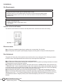
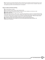
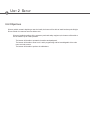
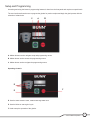
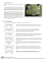
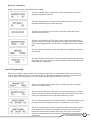
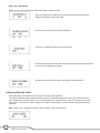
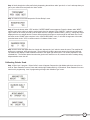
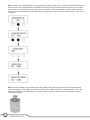
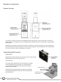
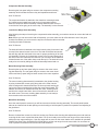
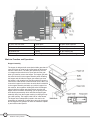
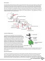
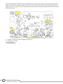
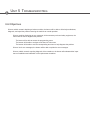
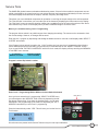
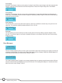
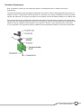
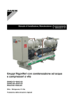
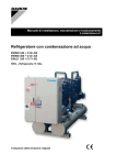
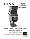
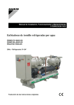
BUNN® TECHNICAL TRAINING
G9WD-RH
Index
Unit 1: Installation
Site Requirements............................................................................................................... 4
Location of the Serial Number........................................................................................... 4
Electrical Install................................................................................................................... 4
Burr Adjustments................................................................................................................ 4
Hopper Install and Coffee Grinding................................................................................... 5
Unit 2: Setup
Setup and Programming..................................................................................................... 7
User Interface................................................................................................................ 7
Programming Lockout.................................................................................................. 8
Level 1 Programming.......................................................................................................... 8
Level 2 Programming.......................................................................................................... 9
Calibrating the Selected Coffee......................................................................................... 10
Calibrating Grinder Scale................................................................................................... 11
Unit 3: Machine Composition
Exterior Overview................................................................................................................ 14
Product Outlets and Removable Parts....................................................................... 14
Accessing the Inside of the Grinder and Internal Assemblies........................................ 14
Control Panel................................................................................................................. 14
Component Bracket Assembly.................................................................................... 15
Load Cell or Weigh Scale Assembly........................................................................... 15
Motor Mounting Plate Assembly................................................................................. 15
Motor/Burr Assembly.................................................................................................... 15
Machine Function and Operations..................................................................................... 16
Hopper Assembly.......................................................................................................... 16
Grind System................................................................................................................. 17
Load Cell or Weigh Scale............................................................................................. 17
Display/Control Panel................................................................................................... 17
Unit 4: Preventive Maintenance
Preventive Maintenance...................................................................................................... 20
Prior to Servicing the Grinder............................................................................................ 20
PM Steps.............................................................................................................................. 20
Unit 5: Troubleshooting
Service Tools....................................................................................................................... 23
Test Outputs.................................................................................................................. 24
Test Switches................................................................................................................ 24
Test Frequency.............................................................................................................. 24
Error Messages.................................................................................................................... 24
Transducer Replacement Special Instructions................................................................. 25
Rev. A
© 2010 Bunn-O-Matic Corporation. All Rights Reserved
Unit 1 Installation
Unit Objectives
Given a realistic scenario depicting a new site install, the learner will be able to install and setup the Weight
Driven Grinder for customer turnover without error.
Given a new machine, all the necessary tools and safety equipment, the learner will be able to install the Weight Driven Grinder without error.
The learner will be able to verify that the site requirements have been met.
The learner will be able to locate and document the serial number.
The learner will be able to install, power up, and perform the burr adjustment procedure.
The learner will be able to install the hopper, coffee beans and start a coffee grind cycle.
Installation
Site Requirements
Space
• G9WD-RH is only for indoor use on a sturdy counter or shelf
• Adequate space must be available above the grinder to raise the lids when adding beans
• G9WD-RH dimensions is 29.1”H x 9.0” W x 16.0” D (73.9cm H x 22.8cm W x 40.6cm D)
• Weight 67 lbs
Electrical
• 120vac, 2 wire plus ground
• 15Amp circuit breaker, single phase, 60 Hz
• ¾ H.P. Motor
Location of the Serial Number
The machine’s serial number is located on the data plate which is located on the lower rear housing.
Electrical Install
Step 1: Plug-in the attached cordset from the grinder into a conventional 120 volt outlet.
Step 2: The grinder LCD (Liquid Crystal Display) will light up and the grinder is ready for the Burr Adjustment.
Burr Adjustment
The grinder is Factory Set at “Drip” grind but can be set from fine to very coarse grind. The following procedures
should be used to make adjustments before initial set-up of the hopper and coffee beans.
Step 1: Remove two black screws from the lower control panel bezel.
Step 2: Remove the control panel and hang the control panel on front of grinder by inserting metal tabs on the back
of control panel into slots on the front of grinder.
Step 3: Make sure funnel with filter is placed in the funnel rails. Go to the “GRIND MOTOR” menu under the level
1 “SERVICE TOOL?” menu, and press the button under “ON” to start the motor. Slowly turn the adjust¬ing screw in
a clockwise direction until a metallic whine is heard due to the rubbing of the grinding burrs. Reverse the adjusting
screw just until the whining stops. Turn off the motor and exit to home screen.
Step 4: Rotate the white plastic cap on the end of the grinder with the “0” aligned with the adjusting screw slot.
Step 5: The following settings approximately correspond to the CBC recognized grinds. FINE GRIND: Rotate the
adjusting screw to the “7” in a counterclockwise direction. DRIP GRIND: Rotate the adjusting screw to the “8” in a
counterclockwise direction. Regular (Coarse) Grind: Rotate the adjusting screw to the “12” counterclockwise
direction.
4
Step 6: Reinstall front control panel.
G9WD-RH Training Manual
Note: The grind may need further adjustment after the initial setup of the hopper and coffee bean grind test. You will
need to remove the hopper and run grind cycles until all of the coffee in the grind chamber is dispensed. Repeat the
burr adjustment procedure until the desired grind is accomplished.
Hopper Install and Coffee Grinding
Step 1: Install hopper onto base.
Step 2: Fill hopper with whole beans. Hopper capacity is 6lbs.
Step 3: Place a paper filter into the brew funnel. The filter must not be folded-over or tilted to one side.
Step 4: Insert the funnel into the funnel rails until it stops.
Step 5: Select batch size.
Step 6: Momentarily press the “START” switch. The grinding will begin after a moment. The recipe and actual weight
of the coffee being ground into the funnel will be shown on the display during grinding. The grinder will automati¬cally
stop when the correct weight is reached. DO NOT TOUCH THE FUNNEL OR FUNNEL HANDLE DURING GRINDING. THIS WILL CAUSE THE INCORRECT WEIGHT OF COFFEE TO BE GROUND.
Step 7: Remove the funnel from the grinder and level the bed of grounds by gently shaking.
Step 8: The loaded funnel is now ready for use in any commercial drip coffee brewer according to the
manufac¬turer’s instructions.
5
Bunn-O-Matic Corporation
Unit 2 Setup
Unit Objectives
Given a realistic scenario depicting a new site install, the learner will be able to install and setup the Weight
Driven Grinder for customer turnover without error.
Given an installed machine, all the necessary tools and safety equipment, the learner will be able to set the machine up for initial operation.
The learner will be able to operate the interface touchpad panel.
The learner will be able to enter level 1 and 2 programming and be knowledgeable of the main menu and sub screens.
The learner will be able to perform the calibrations.
Setup and Programming
Accessing and using the brewer’s programming features is done from the front panel and requires no special tools.
The user interface allows the user to program the grinder for product recipes and begin the grind process with the
selection of a batch size.
C
A. Hidden buttons used to navigate setup and programming menus.
B. Hidden button used to access the programming menus.
C. Hidden button used to navigate the programming menus.
Operating Controls
D
E
F
D. Used to select between small, medium and large batch size.
E. Used to initiate or start a grind cycle.
F. Used to stop the operation of the grinder.
7
Bunn-O-Matic Corporation
Programming Lockout
Disconnect grinder from power source before removing any
panel.
The program lockout switch is located on the main control
board. Accessing the lockout switch, you will need to remove
the switch panel by removing two standard screws. The lockout switch is located on the rear lower corner of the CBA.
This switch can be set to prevent change to the programming settings of the brewer. Once all the correct settings are
programmed, the operator can set the switch to the “Lock”
position to prohibit anyone from changing the settings. With
the switch in the “Lock” position, the programming menus can
still be accessed to view the current settings. However, no
changes will be saved. The menu will display a message “Memory is locked, constant change is not possible” when
you enter the programming menus.
Level 1 Programming
Press and hold the switch labeled “B” in the diagram for 1 second to enter Level 1.
The menu is used to select the coffee name from the recipe list and will keep record of the total pounds used for the selected coffee flavor or coffee name.
This function screen prompts the user to enter in a password to advance
farther into programming. If a password has not been set then access is
allowed by advancing through the programming screens.
This function allows the operator to set a password to be entered at the “Enter Password” screen. The password is set to prevent access to certain levels of programming so that setup functions can not be altered.
This function has two parts. It allows the operator to view the recipe parameters settings and allows the operator to modify any of the recipe settings for a particu-
lar coffee name.
ENTER ASSET #
AN000000
This function allows the operator to enter in an optional asset number. This can be useful for tracking the usage or service of an individual machine within a group.
This function enables the operator to enter in to the diagnostic section of
programming. The items that can be checked vary from machine to machine. This is a feature that aides in troubleshooting and test individual input and out-
puts.
Selecting “Yes” will reset all of the previously entered settings and
calibrations. Factory preset default values will replace all previous settings.
8
G9WD-RH Training Manual
New Level 1 Sub-Menus
Below are new sub-menus associated with the G9WD.
This menu sets the “offset” weight for the coffee name selected so accurate weight grinding will be achieved.
This menu allows selection of scale test and will prompt you to tare the funnel and add a calibrated weight to check the scale.
This menu is prompted in the “Test Scale” menu which allows the present weight/funnel to be tarred.
This menu is prompted in the “Test Scale” menu to show the measurement of weight in ounces. The weight being applied to the load cell has a direct relation to the electrical signal which is converted into a readable format called “Sensor Bits”.
This menu allows the switches on the control panel to be disabled for servicing of the grinder
This menu shows the total amount of the coffee which has been ground through the grinder. The running total can be used to determine when the grinding burrs need cleaning or replacement.
Level 2 Programming
Enter Level 1 program. “Select Coffee” menu will appear. Depress the “B” (right hidden) switch one more time to
scroll to “Enter Password” screen. Press and hold the “B” (right hidden) switch for 3 seconds in “Enter Password”
menu to enter Level 2 programming. Level 2 programming will begin with “Machine Type” menu.
The menu is used to select between option of using the grinder as a weight based or time based grinder.
The menu allows calibration of the scale. It is recommended to use a precision weight to accurately calibrate the scale to the main control board during a PM or service part replacement of the weigh scale (transducer) or CBA.
The menu allows adjustment of the “Max Bit Spread”. The Max Bit Spread is the maximum deviation permitted in the array to accept the tare of the funnel.
The menu is used to select between the options of which style grinder is being used, grinders with or without the read/write coils. Smart funnels are used to transfer information between grinder and brewer. Two pieces of information writes to the transponder and is read from the brewer which is batch size and coffee name.
Bunn-O-Matic Corporation
9
New Level 2 Sub-Menus
Below are new Level 2 sub-menus associated with the Calibrate Scale
The menu allows you to adjust for the known precision weight which will be added for calibration of the weigh scale.
The menu allows scale to be tarred for calibration.
This screen is displayed while scale is being tarred.
An instructional screen directing the user to place precision weight inside funnel to continue the calibration procedure.
The last menu screen shown when completing the scale calibration.
Calibrating Selected Coffee
After initial setup, coffee name must be selected from the coffee profile list.
The machine will keep track of selected coffee weight in total pounds and ounces used. The “Calibrated Coffee”
menu located in the “Review Recipe” menu will follow after the “3 Batches Done” menu. The purpose of the “Calibrate Coffee” menu sets the “offset” weight for the coffee name selected, so that accurate weight grinding will be
achieved.
Step 1: Enter level 1 program and stop at “Select Coffee” menu and select yes.
10
G9WD-RH Training Manual
Step 2: Scroll through the coffee profile list by depressing the switches under “previous” or “next” and stop when you
get to your coffee flavor and press the “done” switch.
Step 3: Continue to scroll and stop at the “Review Recipe” menu.
Step 4: Press the button under “YES” and the “COFFEE NAME” screen appears. Press the button under “NEXT”
until the name of the coffee you wish to set the batch sizes for appears. Press “MODIFY” under the screen containing the name of the coffee you wish to set the batch sizes for. Using the buttons under (-) and (+), change the weight
displayed to the new weight desired. Press a different batch size button to set the weight for that batch size. Press
the button under “DONE” when complete. In the “3 BATCHES DONE” menu, if no further changes are to be made,
press the button under “YES” to continue onto the “Calibrate Coffee” menu.
Step 5: Insert funnel with paper filter into funnel rails, depress the “yes” switch to enter the menu. The machine will
prompt you a message “press grind to start”. The machine will grind the target set amount of weight and will stop.
The machine will display a coffee calibration number in the upper right hand corner. The number represents “shut
off ahead bits”. The number determines when the grind motor needs to turn off, because the coffee is always being
dispensed after motor shut off.
Calibrating Grinder Scale
Step 1: Enter level 1 program. “Select Coffee” menu will appear. Depress the right hidden switch one more time to
scroll to “Enter Password” screen. Press and hold the right hidden switch for 3 seconds in “Enter Password” menu to
enter level 2 programming. Level 2 programming will begin with “Machine Type” menu.
11
Bunn-O-Matic Corporation
Step 2: Scroll to the “Calibrate Scale” menu and depress the switch under yes. The machine will prompt the following
menus in order. The grinder/scale will be calibrated at the factory. Upon final placement of the grinder, service issue
arises which requires replacing the control board or the transducer, it is recommended to use the typical funnel and
recipe weight in recalibrating the grinder scale after part replacement. The range of the “Calibration Oz.” menu is 3 to
16 ounces.
Note: A Precision weight will be needed to accurately calibrate the weigh scale (transducer) to the Control Board.
If precision weight is not available, proceed with a known object weight (ounces) for “Calibration Scale” menu. The
transducer and CBA will be calibrated but a precision weight will still be needed for precise calibration of the two
components together.
12
G9WD-RH Training Manual
Unit 3 Machine Composition
Unit Objectives
Given a realistic scenario in which the learner has access to the machine’s internal components the learner
will understand the composition and functions of the Weight Driven Grinder.
Given a realistic scenario requiring the learner to access the internal components of the machine the learner will be able to remove the top cover, front /rear access covers and access the corresponding internal components.
The learner will disconnect the electrical.
The learner will remove the top, front /rear panel, hopper and control panel.
The learner will be able to remove the control, component bracket, load cell and motor mounting plate assembly.
Given an operating machine the learner will be able to give a general explanation of how the unit operates.
The learner will be able to identify the components and functions of the hopper system.
The learner will be able to identify the components and functions of the grind system.
The learner will be able to identify the components and functions of the weigh scale system.
The learner will be able to identify the functions of the main control board.
Machine Composition
Exterior Overview
The majority of service work done to the G9WD-RH grinder will require the service technician to access the
inside of the unit. The grinder has four removable panels to facilitate access- the control panel, front/rear panel
and top panel.
Depending on the repair the technician may have to remove one or all of these panels. In order to work safely
the power should be disconnected prior to removal of any body panel. Once the panels are removed the power
can be reconnected in order to troubleshoot the machine.
Internal Assemblies Overview
Control Panel
Removing the control panel will give you access to the grind chamber,
dechaffer plate thumb screw and main CBA.
How to Remove
The control panel is attached to the main housing by 2 slotted
screws. Depending upon the model, you may disconnect 3
or 4 connectors from the CBA to release the control panel
entirely from the machine.
Removing the front panel will give access to the component
mounting assembly which includes the motor relay and stepdown transformer.
14
G9WD-RH Training Manual
Grind Chamber
White Cap Burr
Location Indicator
Dechaffer Assembly
Thumb Screw
Component Bracket Assembly
Removing the front panel will give access to the component mounting
assembly which includes the motor relay and stepdown transformer.
How To Remove
The component bracket is attached to the transducer mounting bracket
by 1 slotted screw located lower right corner of component bracket.
Slide the component bracket assembly outward and disconnect the 4 pin connector going to the stepdown transformer and the four wires going to the motor relay. The assembly is now removed.
Load Cell or Weigh Scale Assembly
After following the steps of removing the component bracket assembly, you now have access to remove the load cell
assembly.
Note: Before you can remove the load cell assembly, you must make sure all coffee beans are out of the grind
chamber first before you can remove the top lid to access the cable mount that
is holding the load cell harness.
How To Remove
The load cell bracket is attached to the lower base by using 2 star nuts in the
rear and 2 hex slotted screws in the front. The load cell bracket has notches
that will align with the weld studs in the rear for proper positioning of the load
cell assembly. Remove the 2 slotted hex screws in the front and loosen the 2
star nuts in the rear. Disconnect the load cell 4 pin connector at the CBA and
release harness out of the cable clamp under the top lid. The load cell is now
ready to be removed by sliding the load cell assembly forward and out.
Motor Mounting Plate Assembly
Removing the top and rear panel will give access to the motor mounting plate assembly. The rear panel will give access to the motor electrical box and the top panel will give better access to the motor capacitor.
How To Remove
The motor mounting plate assembly is attached to the grinder housing
by using 4 slotted hex screws going along side of the motor into the
trunk housing and 2 slotted screws from the front top hood housing going into the motor mounting plate, pulling the motor plate forward. The
harness will need to be disconnected from the motor, chassis ground
and from the control board. Also, wires will need to be released out of
the cable mount. The motor mounting plate assembly is now ready to
be removed out the rear of the machine.
Motor/Burr Assembly
Once the control panel is removed, you will have access to the burr housing assembly. The control panel bracket
tabs can be inserted into the tab openings on the housing to hold the panel in position for operation and adjusting of
the grind burrs.
How To Remove
Remove 2 slotted hex screws from the burr housing cap. Remove burr housing with adjustment screw and continue
removing the burr rotor cup and the shear plate. You are now ready to remove the rotor auger off the motor shaft by
pulling the rotor auger toward you. If the rotor auger will not move on the motor shaft a tool is available for purchase
called a Burr Rotor Puller Kit (BUNN P/N:27680.000) to pull the rotor auger from the motor shaft. You now have access to posterior and anterior burrs and motor shaft extension.
Bunn-O-Matic Corporation
15
1. 120 or 230 volt motor
6. Shear plate
11. Motor shaft extension
2. Burr housing
7. Burr rotor cup
12. Screw (Attach Burr)
3. Screw
8. Anterior burr
13. Grind adjustment screw
4. Posterior burr
9. Spring
14. Burr housing cap
5. Rotor auger
10. Bushing
15. Screw (Attach Housing)
Machine Function and Operations
Hopper Assembly
The hopper is designed with a mechanical slide gate that will
open and close an outlet for the coffee beans to fall through
and into a bean chute. The slide gate operates by the use
of a magnet and a strike block to open and close the gate
when you install or remove the hopper. The hopper gate with
the strike block will hit the magnet assembly when installing
the hopper and will slide the hopper gate toward you when
the hopper is fully installed onto the base which will open the
outlet for the coffee beans to enter the bean chute. When you
remove the hopper from the base, the strike block is adhered
to the magnet assembly and when you pull the hopper from
the machine, the magnetism holding the strike block/hopper
gate will slide the hopper gate closed when removing the
hopper from the machine. Essentially you are pulling on the
strike block/gate assembly which will slide the hopper gate
assembly away from the magnet resulting in closing the hopper outlet opening. The hopper holds 6 lbs of coffee beans.
The hopper has a transponder located in the rear for the
acceptance of read/write of coffee flavor name for the hopper.
Not all weight driven grinders will have the read/write capability and will be model specific.
16
G9WD-RH Training Manual
Grind System
Once the coffee beans fall through the hopper outlet and fill the bean chute, the bean chute directs the coffee beans
to the grind chamber. When the motor is commanded to turn on, the rotor auger assembly starts rotating and the
coffee beans are now being fed down the auger into the gap between the front and rear burr. After the beans have
been ground to particle size, the ground coffee exits out the burr housing opening into the dechaffer chute and into
the funnel. The purpose of the dechaffer assembly is to help reduce static electricity from the chaff before going into
the funnel. A procedure is documented in the manual on setting the coarseness of the grind. What you are doing is
setting the gap between the burrs for the type of grind. Ex: Fine, Drip or Regular etc…Exact adjustment will vary according to the bean roast or added flavoring.
Indicator Adjustment Cap
Thumb Screw
Load Cell or Weigh Scale
The weigh scale is comprised of a funnel rail bracket assembly, funnel guide, transducer bracket, shoulder bolt and
transducer. The funnel rail assembly and funnel guide attach
to the load side of the transducer. The transducer is mounted
to the bracket by 2 hex bolts in the bottom of the transducer
and the shoulder bolt is mounted in the front bottom of the
transducer. The shoulder bolt is used as a safety device that
limits the travel of the transducer if someone applies upward
pressure on the funnel rail assembly. The transducer (bending beam cell) is the main component that will sense the
force or weight that is applied on the funnel rail assembly
and will convert the weight into analog electrical signal. The
bending beam load cell will deform when weight is applied to
the beam which will change the electrical resistance of the
gauges mounted on top and bottom of the beam. The electrical signal is converted to a readable readout called “bits”
and is solved by the algorithm in the software to display the actual weight in ounces on the display during portion
grind dispense.
Display/Control Board
The main control is the brain of the grinder. The control board is the single component that contains all of the standard or customer specific programming software. The CBA interprets the data it receives from the transponder
through the read/write coil and is waiting for the user input command through the switch membrane to activate the
selected recipe by depressing the grind switch. The CBA reads the recipe and will in return activate an output to the
relay to turn on the motor. The recipe sequence will run the amount of weight or time in the recipe. The weigh scale
Bunn-O-Matic Corporation
17
version will send input information back to the CBA and will shut off the output to the motor relay when the desired
weight is achieved. The weight input data is referred or seen as the term called “Bits” in the programming. When the
grinder is set in the “weight” mode, it will always tare the funnel when you depress the grind switch and then start the
grind recipe process.
J1 Stepdown Transformer 120/12 VAC and K1-Relay Coil
J7 Load Cell 12-14 VDC
J12 Funnel Sensor
J13 Switch Membrane
18
G9WD-RH Training Manual
Unit 4 Preventive Maintenance
Unit Objectives
Given a realistic scenario depicting a machine requiring a preventive maintenance, the learner will be able to
identify which elements of a component need to be serviced without error.
Given a machine, all the necessary tools and safety equipment, the learner will be able to identify the components that need to be serviced for the PM.
Preventative Maintenance
In order to maintain proper operation and long service life BUNN recommends performing the preventive maintenance every 6 months. Individual customers will vary with some customers choosing not to receive preventive
maintenance. Some of the PM items may require more frequent maintenance depending on the site conditions and
usage.
Tools Required:
□□ Small & Medium standard blade screwdriver
□□ Small Phillip screwdriver
□□ Rotor Puller (P/N:27680.0000)
□□ Non metallic bristle brush
□□ Scotch-Brite pad
□□ Cloth
□□ Precision weight between 3 and 16 ounces
□□ Digital weigh scale
PM Parts:
□□ Dechaffer Plate, BUNN P/N: 05995.1000
Prior to servicing the grinder:
□□ The grinder will keep a running total of the pounds of coffee the grinder has ground. This running total is shown in the “PmBurrsLbs #” menu, under the “SERVICE TOOLS” menu. This running total can be used to determine when the grinding burrs need cleaning or replacement. Pressing the button under “RESET” will reset this total to zero.
□□ Remove the coffee bean hopper from the grinder base and empty.
□□ Start a grind cycle to grind the remaining coffee beans out of the chute and grind chamber.
□□ Unplug grinder before the removal of any panel or grind chamber housing parts.
PM Procedures
Step 1: Clean the hopper assembly
□□ Clean and sanitize the hopper and lid. Care should be taken not to scratch the hopper with any abrasive material.
□□ Install and remove the hopper from the grinder base while inspecting the hopper gate assembly on the bottom of the hopper for correct operation of opening and closing of the hopper gate.
□□ Make sure the hopper is dry before use.
Step 2: Clean the grind chamber
□□ Remove two black screws from the lower control panel bezel.
□□ Remove the control panel and hang the control panel on front of grinder by inserting metal tabs on the back of control panel into slots on the front of grinder.
□□ Remove the two screws holding the front cover to the burr housing. Carefully remove the burr housing front cover. Clean inside surface with a dry stiff non-metallic bristle brush and wipe with a dry clean cloth.
□□ Carefully remove the rotor cup, shear plate, burr rotor and motor shaft extension from the grinder. Clean all parts with a dry stiff non-metallic bristle brush and wipe with a dry clean cloth.
Note: If you are unable to remove the burr rotor by hand, the rotor puller kit will be needed to remove the burr rotor.
□□ Clean the grind chamber and burrs with a dry stiff non-metallic bristle brush and wipe with a dry clean cloth.
□□ Clean the motor shaft with a Scotch-Brite pad and the inner portion of the burr rotor assembly.
□□ Reinstall the motor shaft extension, burr rotor, shear plate, rotor cup and front cover to the burr housing.
□□ The burrs will need to be adjusted after cleaning. Refer to the “Adjustment” section of the Installation & Operating manual.
Step 3: Inspect and clean the dechaffer plate
□□ Unscrew the thumb screw holding the dechaffer bracket in the coffee chute outlet.
□□ Reach underside the coffee chute and pull downward on the dechaffer bracket while pushing on the locator but
ton to remove the dechaffer bracket assembly.
□□ Clean the dechaffer plate with cloth or replace the dechaffer plate if it is broken or missing from the bracket.
□□ Re-installation is opposite from removal.
□□ If replacing the dechaffer, make sure it has clearance and does not rub.
20
G9WD-RH Training Manual
Step 4: Scale calibration
□□ After cleaning of the hopper, grind chamber, dechaffer plate and grind burr adjustment, you should perform the grinder scale calibration with a precision weight for optimum performance. If no precision weight is available, then do not proceed with the calibration procedure.
□□ Reinstall the hopper and front control panel.
□□ Refill the hopper with coffee beans.
□□ Plug in the grinder. Refer to the “Grinder Scale Calibration” procedures outlined in the Installation and Operating manual.
Note: The adjustment range for “Calibration Oz” menu is 3 to 16 ounces. A precision weight between the parameter
ranges can be used but is recommended to use a precision weight matched with the typical weight recipe volume
being used.
21
Bunn-O-Matic Corporation
Unit 5 Troubleshooting
Unit Objectives
Given a realistic scenario depicting a broken machine, the learner will be able to effectively troubleshoot,
diagnosis, and repair the problem returning the machine to normal operation.
Given a machine displaying an error message, all the necessary tools and safety equipment, the learner will be able to diagnosis the problem.
The leaner will be able to access the programming menu.
The learner will be able to navigate to the Service Tools menu.
The learner will be able to use the corresponding test menu to help diagnose the problem.
Given a list of error messages, the learner will be able to explain the error messages.
Given a realistic scenario requiring diagnosis of the transducer, the learner will understand the impor
tance of installation and calibration of the replacement transducer.
Service Tools
The G9WD-RH grinder features on-board troubleshooting menus. Since all of the machine’s components are controlled or activated by the control board you can activate and test load components individually from the user interface switch/display board and test the outputs, switches, frequency and weigh scale.
This allows you to test individual components for operation or receiving the output voltage to the said component.
The “Test switches” menu allows you to test the input of the buttons by displaying the button name on the display.
The “Test Scale” menu converts the electrical voltage into a readable form on the menu referred to as “Bits’ and is
also referenced by ounces on the display when you add a calibrated weight to check the scale.
Memory is Locked Accessing Level 1 Programming
The program lockout switch is to prohibit anyone from changing the settings. The menus can be accessed to view
the current settings. However, no changes will be saved.
Enter the level 1 program by depressing and holding the hidden switch for 1second or until display reads “SELECT
COFFEE” and release.
If the Program lockout switch is turned to the “LOCK” position and you enter level 1 programming, the following
menus will display and scroll reminding you the memory is locked and stop on the “SELECT COFFEE” screen.
If you try and reload “FACTORY CONSTANTS” while in the lock mode, the display will keep scrolling the “MEMORY
IS LOCKED” menu screens.
!!! CAUTION !!!
MEMORY IS LOCKED
CONSTANT CHANGE
IS NOT POSSIBLE
Program Lockout Dip Switch Location
Enter Level 1 Programming With or Without Lockout Switch Activated
Once you have entered level 1 programming “SELECT COFFEE”menu,
you will navigate to the “SERVICE TOOLS menu by depressing the hidden button consecutively. If you pass the intended menu, you can step
backwards in the programming by the means of depressing the “LEFT
HIDDEN” button while you are in level 1 programming.
Hidden Buttons
Press the button directly under “YES”. This will enter you into the Service
Tool function.
Six sub menus are present under Service Tools but only four can help troubleshoot.
23
Bunn-O-Matic Corporation
Test Outputs
Accessing “Test Outputs” will give you the option of turning On and Off the output voltage to the load component individually. A voltmeter can be used across the load component to measure the output voltage when commanded.
TEST OUTPUTS ?
NO
YES
Test Switches
Accessing “Test Switches” will give you the option of depressing the control switch individually and displaying the
switch name on the display screen for switch recognition. Depressing “Hidden Program” button will exit and take you
to the third sub service menu.
TEST SWITCHES ?
NO
YES
Test Frequency
The menu screen is used to see and test the frequency value for the read/write coils that may or may not be on the
equipment. The read/write capability operates between 124 to 127 Khz.
TEST FREQUENCY ?
NO
YES
Test Scale
The menu allows you test the scale by the means of tarring the funnel and by adding a precision weight to check
the scale. The electrical signal is converted to readable information on the display called “Bits” and is referenced by
weight in ounces.
TEST SCALE ?
NO
YES
Error Messages
GRIND ERROR
RELOAD HOPPER
The error message appears when you start a grind cycle and the weight stops increasing on the display and does not
complete the target weight. The grind cycle will abort and display the error message “Grind Error Reload Hopper” for
5 seconds and return back to the home screen “Ready To Grind”.
SCALE UNSTABLE
PLEASE TRY AGAIN
The “Scale Unstable Please Try Again” error message appears when you depress the grind button and the CBA cannot tare the funnel within the allowable time frame of 20 seconds. The message will display for 5 seconds and return
back to the home screen “Ready To Grind”.
24
G9WD-RH Training Manual
Transducer Replacement
Note: If transducer is broke you can change the grinder to a timed grinder until it is repaired. See level 2
programming.
The load cell (transducer) with strain gages is designed to be used in a variety of harsh applications but can be susceptible for failure. The transducer could fail because of overloading, over voltage, mishandling or moisture penetrating pass the cable seal. The symptom or problem of the transducer could be unreliable readings or no readings at all.
Care must be taken when re-installing the replacement transducer. Route transducer wires away from sharp edges
and follow the recommended torque of 60 inch lbs. for the mounting of the funnel rail assembly to the load side of the
transducer and the installation of the transducer to the platform or bracket. Loctite should be used on the screws.
It is very important to use a precision weight to calibrate the new replacement transducer to the main control board.
25
Bunn-O-Matic Corporation