1
Setup Guide
Contents
Introduction . . . . . . . . . . . . . . . . . . . . . . . . . . . . . . . . . . . . . . . . . . . . . . . . . . . . . . . . . .1
How to Use This Manual . . . . . . . . . . . . . . . . . . . . . . . . . . . . . . . . . . . . . . . . . . .1
Before You Begin: Check DM Pro Kit Component List
Rack and Mounting Hardware Checklist . . . . . . . . . . . . . . . . . . . . . . . . . . . . .2
Trigger Pad Checklist . . . . . . . . . . . . . . . . . . . . . . . . . . . . . . . . . . . . . . . . . . . .2
Cable Checklist . . . . . . . . . . . . . . . . . . . . . . . . . . . . . . . . . . . . . . . . . . . . . . . .3
DM Pro Drum Module Checklist . . . . . . . . . . . . . . . . . . . . . . . . . . . . . . . . . . .3
Documentation Checklist . . . . . . . . . . . . . . . . . . . . . . . . . . . . . . . . . . . . . . . . .3
Items You Will Need . . . . . . . . . . . . . . . . . . . . . . . . . . . . . . . . . . . . . . . . . . . . . . . .3
Assembling Mounting Rack . . . . . . . . . . . . . . . . . . . . . . . . . . . . . . . . . . . . . . . .3
Attaching Pads and Cymbals
Snare . . . . . . . . . . . . . . . . . . . . . . . . . . . . . . . . . . . . . . . . . . . . . . . . . . . . . . . .6
High Tom . . . . . . . . . . . . . . . . . . . . . . . . . . . . . . . . . . . . . . . . . . . . . . . . . . . . .7
Mid Tom . . . . . . . . . . . . . . . . . . . . . . . . . . . . . . . . . . . . . . . . . . . . . . . . . . . . .7
Low/Floor Tom . . . . . . . . . . . . . . . . . . . . . . . . . . . . . . . . . . . . . . . . . . . . . . . .8
Hi-Hat Cymbal . . . . . . . . . . . . . . . . . . . . . . . . . . . . . . . . . . . . . . . . . . . . . . . . .8
Crash Cymbal . . . . . . . . . . . . . . . . . . . . . . . . . . . . . . . . . . . . . . . . . . . . . . . . .8
Ride Cymbal . . . . . . . . . . . . . . . . . . . . . . . . . . . . . . . . . . . . . . . . . . . . . . . . . .9
DM Pro Rack Mounting Tray . . . . . . . . . . . . . . . . . . . . . . . . . . . . . . . . . . . . .9
Kick Drum Trigger . . . . . . . . . . . . . . . . . . . . . . . . . . . . . . . . . . . . . . . . . . . . .10
Hi-Hat Pedal . . . . . . . . . . . . . . . . . . . . . . . . . . . . . . . . . . . . . . . . . . . . . . . . .10
Installing DM Pro Module and Attaching Cables
Install Sound Module . . . . . . . . . . . . . . . . . . . . . . . . . . . . . . . . . . . . . . . . . . .10
Label Cables . . . . . . . . . . . . . . . . . . . . . . . . . . . . . . . . . . . . . . . . . . . . . . . . .10
Connect DM Pro Module and Trigger Pads . . . . . . . . . . . . . . . . . . . . . . . . . .10
Ready to Play
Adjust Drum Head Tension . . . . . . . . . . . . . . . . . . . . . . . . . . . . . . . . . . . . . .11
Adjust Triggering Parameters . . . . . . . . . . . . . . . . . . . . . . . . . . . . . . . . . . . . .12
Select a Drumkit . . . . . . . . . . . . . . . . . . . . . . . . . . . . . . . . . . . . . . . . . . . . . .12
Advanced User Tips and Tricks
Hi Hat Pedal . . . . . . . . . . . . . . . . . . . . . . . . . . . . . . . . . . . . . . . . . . . . . . . . . .13
Snare Pad . . . . . . . . . . . . . . . . . . . . . . . . . . . . . . . . . . . . . . . . . . . . . . . . . . . .13
Ride Cymbal . . . . . . . . . . . . . . . . . . . . . . . . . . . . . . . . . . . . . . . . . . . . . . . . .14
Tom Pad . . . . . . . . . . . . . . . . . . . . . . . . . . . . . . . . . . . . . . . . . . . . . . . . . . . . .14
Crash Cymbal . . . . . . . . . . . . . . . . . . . . . . . . . . . . . . . . . . . . . . . . . . . . . . . .14
Kick Trigger . . . . . . . . . . . . . . . . . . . . . . . . . . . . . . . . . . . . . . . . . . . . . . . . . .14
DM Pro Kit Setup Guide
Introduction
Thank you for purchasing the Alesis DM Pro Kit. It’s a complete electronic percussion
system that combines Alesis’ top-of-the-line DM Pro drum module with state-of-the-art
drum pads, mounting hardware and connecting cables. Flexible, powerful and durable, the
DM Pro Kit is an all-in-one solution for everyone from hobbyists to pro drummers.
To assure proper setup and take full advantage of the DM Pro Kit’s wide-ranging features, please
read this Setup Guide and the DM Pro Module Reference Manual carefully.
How to Use This Manual
This Setup Guide is designed to help you configure your DM Pro Kit to the “power on”
stage. Please refer to the DM Pro Module Reference Manual for advanced instructions on
playing, programming and fine-tuning your percussion sounds.
When something important appears in this manual, an icon (like the one
J on
the left) will appear in the left margin. This symbol indicates that this
information is vital when setting up and operating the DM Pro Kit.
Assembly instructions are phrased for setting up a typical right-handed drum kit. Whether
you’re right-handed or left-handed, you can easily adjust and configure the DM Pro Kit to
accommodate your playing preferences.
Assembly instructions are phrased from the drummer’s point of view – that is, “right” and
“left” are used to describe procedures as if you are sitting on your drum throne facing the kit.
Before You Begin: Check DM Pro Kit Component List
The DM Pro Kit package contains everything you need to build a complete electronic
percussion system. The components include five categories:
1) Rack and mounting hardware
2) Trigger pads
3) Cables
4) DM Pro Drum Module
5) Documentation
Before you begin assembly, we recommend that you take an inventory of all the components
and organize them into separate groups. Use a pen or pencil to check off the following
components. If you find that your DM Pro Kit is missing any components, please contact
Alesis Customer Support at 800-5-ALESIS.
DM Pro Kit Setup Guide
1
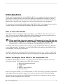
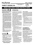
Rack and Mounting Hardware Checklist -(Figure 1)
Qty. Part Description
2
2
1
1
1
4
Qty. Part Description
Rack Bases
Upright Tubes
Center Tube (w/ 3 memory locks)
Right Side Tube (w/ 1 memory
lock)
Left Side Tube (w/ 2 memory
locks)
Rack Tube T-Clamps
8
4
1
2
1
1
2
5
Hardware Clamps
Tom Arms
Long Snare Arm
Cymbal Booms
DM Pro Rack Mounting Tray
w/screws and washers
Small Utility Tray (not pictured)
Drum Keys (not pictured)
Cable Ties (not pictured)
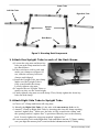
Figure 1: Rack and Mounting Hardware layout
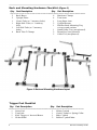
Trigger Pad Checklist
Qty. Part Description
1
3
1
1
2
Snare Pad
Tom Pads
Kick Trigger w/ Inverted Beater
Hi-hat Pedal
Qty. Part Description
1
1
1
2
Hi-hat Cymbal
Crash Cymbal w/ Spring Collar
Ride Cymbal
Rubber Cymbal Mats
DM Pro Kit Setup Guide
Cable Checklist
DM Pro Drum Module Checklist
Qty.
Part Description
Qty.
6
1/4" Mono Cables
3
1/4" Stereo Cables
1
1
1
Part Description
DM Pro Drum Module
Power Supply
DM Pro Module Reference Manual
Documentation/Miscellaneous Checklist
Qty.
1
1
1
Part Description
DM Pro Kit Setup Guide
Color-coded cable stickers
DM Pro Addendum
Items You Will Need
In addition to the drum keys that come with DM Pro Kit, you will need a phillips head
screwdriver and flat head screwdriver. An adjustable wrench or pliers will prove useful
for final tightening of clamps.
For performance, you’ll need to provide four items: a kick drum pedal, a drum throne,
drum sticks and headphones or some other form of monitoring/amplification.
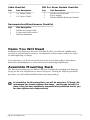
Assemble Mounting Rack
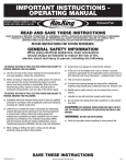
The first step in setting up your DM Pro Kit is to assemble the mounting rack. Begin by
laying out the rack components as shown in Figure 2. During the following assembly
procedure you will build the DM Pro Rack from the ground up.
J
In assembling the Mounting Rack, you will be using four T-Clamps. We
recommend you loosely tighten each clamp – just enough to hold it in
place. After you have completely assembled and positioned the kit, you
can then tighten each clamp securely.
DM Pro Kit Setup Guide
3
Center Tube
Left Side Tube
Right Side Tube
Upright
Tubes
Rack Bases
Figure 2: Mounting Rack Components
1. Attach One Upright Tube to each of the Rack Bases.
a) Loosen the wing nuts and drum key
bolts on each clamp attached to the
two Rack Bases.
b) Place rack bases side by side and
make sure clamps are aligned. If
not, slide the memory lock and
clamps until aligned.
c) Insert the Upright Tube into clamp.
Make sure the Upright Tube is
fully seated inside the clamp.
Loosely tighten wing nuts.
d) Compare the two Upright Tubes to
make sure they are the same height.
e) Firmly tighten wing nuts on each clamp. Then, firmly tighten the drum-key
bolts on each clamp.
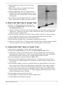
2. Attach Right Side Tube to Upright Tube
a) Choose a T-Clamp and loosen all wing nuts.
b) Identify the Right Side Tube (it’s the tube with one memory lock on it).
c) Attach T-Clamp to Right Side Tube by inserting tube into the clamp opening
marked “tighten first.” Make sure the tube is fully seated in the clamp, and
the opening marked “tighten first” is positioned directly next to the memory
lock. Loosely tighten the wing nuts marked “tighten first.”
d) Loosen memory lock on the Right Side Tube and slide it into the T-Clamp, making
sure you align the memory lock’s notch with the indentation in the T-Clamp.
4
DM Pro Kit Setup Guide
e) Firmly tighten the memory lock’s bolt with
drum key.
f) Select either of the two Upright Tube / Rack
Base assemblies built in Step 1.
g) Slide the Right Side Tube’s T-Clamp onto the
Upright Tube. Position it approximately one foot
from the top of the Upright Tube. Loosely tighten
all wing nuts.
h) Set aside the completed Right Side Tube /Upright
Tube / Rack Base assembly until Step 4 below.
3. Attach Left Side Tube to Upright Tube
a) Choose a T-Clamp and loosen all wing nuts.
b) Identify the Left Side Tube (it’s the tube with
two memory locks on it).
c) Attach T-Clamp to Left Side Tube by inserting tube into the clamp opening marked
“tighten first.” Make sure the tube is fully seated in the clamp. Loosely tighten the
wing nuts marked “tighten first.”
d) Loosen memory lock on the Left Side Tube and slide it into the T-Clamp, making
sure you align the memory lock’s notch with the indentation in the T-Clamp.
e) Firmly tighten the memory lock’s bolt with drum key.
f) Select the other Upright Tube / Rack Base assembly built in Step 1.
g) Slide the Left Side Tube’s T-Clamp onto the Upright Tube. Position it approximately
six inches from the top of the Upright Tube. Loosely tighten all wing nuts.
4. Attach Both Side Tubes to Center Tube
a) Take the two remaining T-Clamps and loosen all wing nuts.
b) Identify the Center Tube (it’s the tube with three memory locks on it).
c) Attach one T-Clamp to each end of Center Tube by inserting tube into the clamp
opening marked “tighten first.” Make sure the tube is fully seated into each clamp,
and rotate the clamps so that they are roughly aligned with each other.
d) Loosely tighten the wing nuts marked “tighten first.”
e) Insert top of left Upright Tube assembly into the T-Clamp on left side of Center
Tube. Insert top of right Upright Tube assembly into the T-Clamp on right side of
Center Tube.
f) For maximum stability, make sure that Rack Bases are perpendicular to the Center
Tube, with all four rubber feet in full contact with the floor. Also, make sure that
Center Tube is level, with each T-Clamp flush with the top of the Upright Tubes.
g) Loosen Center Tube memory locks and slide toward T-Clamps on each end. Slide
each memory lock into its respective T-Clamp, aligning each memory lock’s notch
with the indentation in the T-Clamp.
h) Firmly tighten each memory lock’s bolt.
i) Firmly tighten T-Clamp wing nuts labeled “tighten first.”
j) Firmly tighten all remaining wing nuts.
DM Pro Kit Setup Guide
5
You’ve now assembled the DM Pro Kit’s
Mounting Rack. Before moving on, make sure
that the mounting rack is standing upright and
stable, with all wing nuts securely tightened.
Attaching Pads and
Cymbals
Your next step is to attach pads and cymbals
to the DM Pro Kit Mounting Rack.
J
Remember: all assembly instructions are phrased from the drummer’s
point of view – that is, "right" and "left" are used to describe procedures
as you sit on your drum throne facing the kit.
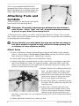
To attach pads and cymbals, you will be using all eight Hardware Clamps. These clamps
have a large wing nut for adjusting their large opening, and a wing nut/hex nut combination
for adjusting their small opening.
J
During assembly, you must tighten the wing nut and hex nut evenly so
that equal pressure is applied on both sides of the clamp opening. This
is necessary to insure maximum stability.
Attach Snare
a) Choose a Hardware Clamp and loosen large wing nut until clamp’s large opening
releases. Attach clamp to far left end of Center Tube, making sure that the clamp’s
large wing nut is facing upward. Tighten large wing nut.
b) Loosen small wing nut and hex nut on Hardware Clamp.
c) Identify Long Snare Arm and attach it to the Center Tube by inserting its open tube
end into the Hardware Clamp. For optimum stability, slide in the Snare Arm until
clamp is at its mid-point. Evenly tighten the hex nut and wing nut, providing equal
pressure on both sides of Snare Arm.
d) Identify Snare Pad. It is different from Tom
Pads – the Snare Pad has a thicker rubber
rim and a blue washer on its output jack.
e) Attach Snare Pad to Snare Arm by inserting
Snare Arm’s splined L-Mount into Snare
Pad. Loosely tighten with drum key.
f) Position Snare Pad at a comfortable height
and angle. Firmly tighten all wing nuts and
drum key bolts.
g) Adjust snare’s memory lock (this is the
memory lock at the middle of the Center
Tube) by loosening its drum key bolt and
sliding it to the left into the Snare Arm’s
Hardware Clamp. Make sure you align the memory lock’s notch with the indentation
in the clamp.
h) Firmly tighten the memory lock’s drum key bolt.
6
DM Pro Kit Setup Guide
Note: for even more flexible positioning of your Snare Pad, you can choose to use your
favorite snare drum stand. The Snare Pad will easily fit any basket-style snare drum stand.
Attach High Tom
a) Choose a Hardware Clamp and loosen large wing nut until clamp’s large opening
releases. Attach clamp to the Center Tube just to the right of the Snare, making
sure that the clamp’s large wing nut is facing you. Tighten large wing nut.
b) Loosen small wing nut and hex nut on Hardware Clamp.
c) Identify Tom Arm and attach it to Center Tube
by inserting its open tube end into the
Hardware Clamp. Evenly tighten the hex nut
and wing nut, providing equal pressure on both
sides of Tom Arm.
d) Choose a Tom Pad – all three Tom pads are
identical to each other and can be used
interchangeably.
e) Attach Tom Pad to Tom Arm by inserting Tom
Arm’s splined L-Mount into Tom Pad. Loosely
tighten with drum key.
f) Position Tom Pad at a comfortable height and
angle. Firmly tighten all wing nuts and drum key bolts.
Note: Tom Pads do not require a memory
lock. You can add memory locks to the DM
Pro Kit’s Toms if you wish. These memory
locks can be purchased at any drum retailer.
Attach Mid Tom
a) Choose a Hardware Clamp and loosen
large wing nut until clamp’s large opening
releases. Attach clamp to far right side of
Center Tube. Make sure that the clamp’s
large wing nut is facing you. Tighten large
wing nut.
b) Loosen small wing nut and hex nut on Hardware Clamp.
c) Identify Tom Arm and attach it to Center
Tube by inserting its open tube end into
the Hardware Clamp. Evenly tighten the
hex nut and wing nut, providing equal
pressure on both sides of Tom Arm.
d) Attach Tom Pad to Tom Arm by inserting
Tom Arm’s splined L-Mount into Tom
Pad. Loosely tighten with drum key.
e) Position Tom Pad at a comfortable height
and angle. Firmly tighten all wing nuts
and drum key bolts.
DM Pro Kit Setup Guide
7
Attach Low/Floor Tom
a) Choose a Hardware Clamp and loosen large wing nut until clamp’s large opening
releases. Attach clamp to far right end of Right Side Tube. Make sure that the
clamp’s large wing nut is facing you. Tighten large wing nut.
b) Loosen small wing nut and hex nut on Hardware Clamp.
c) Identify Tom Arm and attach it to Right
Side Tube by inserting its open tube end
into the Hardware Clamp. Evenly tighten
the hex nut and wing nut, providing equal
pressure on both sides of Tom Arm.
d) Attach Tom Pad to Tom Arm by inserting
Tom Arm’s splined L-Mount into Tom
Pad. Loosely tighten with drum key.
e) Position Tom Pad at a comfortable height
and angle. Firmly tighten all wing nuts
and drum key bolts.
Attach Hi-Hat Cymbal
a) Identify Hi-Hat Cymbal Pad and attach it
to Tom Arm by inserting open tube end of Tom Arm into the underside of Hi-Hat
Cymbal Pad.
b) Firmly tighten Hi-Hat Pad’s wing nut and drum key bolt.
c) Choose a Hardware Clamp and loosen large wing nut until clamp’s large opening
releases. Attach clamp to far left end of Left Side Tube (you’ll need to leave plenty
of room for Crash Cymbal) next to memory lock. Make sure that the clamp’s large
wing nut is facing you. Tighten large wing nut.
d) Loosen small wing nut and hex nut on Hardware Clamp until small opening is released.
e) Attach Hi-Hat to Left Side Tube by inserting arm into the smaller opening of the
Hardware Clamp. Close the clamp and evenly tighten the hex nut and wing nut,
providing equal pressure on both sides of Tom Arm. Be sure to place clamp around
main section of Tom Arm, avoiding the tapered section at the end of the Arm.
f) Position Hi-Hat Pad at a comfortable height and angle. Firmly tighten all wing nuts
and drum key bolts.
g) Adjust hi-hat’s memory lock (this is the memory lock at the far left end of the Left
Side Tube) by loosening drum key bolt and sliding it into the Hi-Hat’s Hardware
Clamp. Make sure you align the memory lock’s notch with the indentation in the clamp.
h) Firmly tighten the memory lock’s drum key bolt.
Attach Crash Cymbal
a) Choose a Hardware Clamp and loosen large wing nut until clamp’s large opening
releases. Attach clamp to far right end of Left Side Tube. Make sure that the clamp’s
large wing nut is facing you. Tighten large wing nut.
b) Loosen small wing nut and hex nut on Hardware Clamp until small opening is released.
c) Identify Cymbal Boom and attach to Hardware Clamp by inserting arm into the
smaller opening of the Hardware Clamp. Close the clamp and evenly tighten the hex
nut and wing nut, providing equal pressure on both sides of Cymbal Boom.
8
DM Pro Kit Setup Guide
d) Identify Crash Cymbal Pad and assemble spring
collar by inserting screw end of spring collar
through bottom of cymbal. Screw top piece of
collar onto threading.
e) Attach Crash Cymbal to Cymbal Boom by inserting
Cymbal Boom’s splined L-Mount into base of
Crash Cymbal spring collar. Tighten using straightblade screwdriver.
f ) Position Crash Cymbal at a comfortable height and
angle. Firmly tighten all wing nuts.
Note: For players who prefer a softer feel and quieter
performance, the DM Pro Kit includes a Rubber
Cymbal Mat that can be attached to the top surface of
the Crash Cymbal.
Attach Ride Cymbal
a) Choose a Hardware Clamp and loosen large wing nut until clamp’s large opening
releases. Attach clamp to top of Right Upright Tube. Make sure that the clamp’s large
wing nut is facing you. Tighten large wing nut.
b) Loosen small wing nut and hex nut on Hardware Clamp until small opening is released.
c) Identify Ride Cymbal Pad and attach to Cymbal Boom by inserting Cymbal Boom’s
tube end into bottom of Ride Cymbal. Tighten drum
key bolt.
d) Attach Cymbal Boom to Hardware Clamp by inserting
Cymbal Boom’s splined L-Mount into the smaller
opening of the Hardware Clamp. Close the clamp
and evenly tighten the hex nut and wing nut, providing
equal pressure on both sides of Cymbal Boom.
e) Position Ride Cymbal at a comfortable height and
angle. Firmly tighten all wing nuts.
Note: For players who prefer a softer feel and quieter
performance, the DM Pro Kit includes a Rubber Cymbal
Mat that can be attached to the top surface of the Ride
Cymbal.
Attach DM Pro Rack Mounting Tray
a) Choose the last remaining Hardware Clamp and loosen large wing nut until clamp’s
large opening releases. Attach clamp to middle of Right Side Tube. Make sure
that the clamp’s large wing nut is facing you. Tighten large wing nut.
b) Loosen small wing nut and hex nut on Hardware Clamp.
c) Attach Rack Tray by inserting mounting tube into the smaller opening of the
Hardware Clamp. Evenly tighten the hex nut and wing nut, providing equal pressure
on both sides of Mounting Tray’s mounting tube.
d) Position Mounting Tray at a comfortable height and angle. Firmly tighten all wing nuts.
DM Pro Kit Setup Guide
9
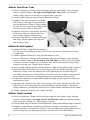
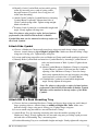
Prepare and Position Kick Drum Trigger
J
Make sure your kickdrum pedal accepts an inverted beater
a) Place Kick Drum Trigger Block behind pedal. Attach your pedal’s clamp to the metal
L-Bracket on the Trigger Block, as you would attach it to the rim of your bass drum.
b) Locate Inverted Beater that comes
with your DM Pro Kit and attach it
to your favorite kick drum pedal as
follows: Loosen the beater clamp.
Remove beater. Insert inverted
beater to underside of beater mount.
Tighten beater clamp.
c) Place your Kick Pedal and Trigger
in a comfortable position.
Position Hi-Hat Pedal
Place beneath Hi-Hat Cymbal Pad in a comfortable position.
You have now completed setup of your Rack Assembly, Pads and Cymbals.
Installing the DM Pro Module and
Attaching Cables
The final steps for setting up the DM Pro Kit involve the DM Pro Sound Module.
Install Sound Module
Open the separate box containing the DM Pro Sound Module, and place the module in the
Rack Mounting Tray. Attach it to the tray using the four rack screws and washers that come
attached to the tray.
Label Cables
The DM Pro Kit comes with color-coded labels for all connector cables. These labels will
make it much easier for you to connect your trigger pads to the DM Pro Sound Module.
Attach matching color-coded labels to the smooth plastic cylindrical surface immediately
above the metal jack at both ends of each cable.
Connect DM Pro Module and Trigger Pads
You are now ready to connect your DM Pro Module to the DM Pro Kit Trigger Pads.
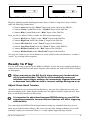
J
10
It’s important to distinguish the three Stereo Cables from the six Mono
Cables. The cables can be identified by looking at their 1/4" plug. Mono
Cables have a two-conductor plug, with separate Tip and Sleeve sections.
See Fig. 3. Stereo Cables can be identified by their three-conductor plug,
with separate Tip, Ring and Sleeve (TRS) sections. See Fig. 4
DM Pro Kit Setup Guide
Figure 3: Mono Cable Plug
Figure 4: Stereo Cable Plug
Begin by identifying and attaching the three Stereo Cables. Using these Stereo Cables,
make the following connections:
• Connect Snare Pad to the “Snare” Input jack on the back of the DM Pro
• Connect Crash Cymbal Pad to the “Cymbal” Input of the DM Pro
• Connect Ride Cymbal Pad to the “Ride” Input of the DM Pro
Next, use the six Mono Cables to make the following connections:
• Connect Kick Drum Trigger to the “Kick” Input of the DM Pro
• Connect High Tom Pad to the “Tom 1” Input of the DM Pro
• Connect Mid Tom Pad to the “ Tom 2” Input of the DM Pro
• Connect Low/Floor Tom Pad to the “Tom 3” Input of the DM Pro
• Connect Hi-Hat Cymbal to the “Hat” Input of the DM Pro
• Connect Hi-Hat Pedal to the “Hat Pedal” Input of the DM Pro
You may use cable ties or Velcro binders to secure cables to the rack hardware, or make a
“snake” by securing cables together.
Ready to Play
You are now ready to power up the DM Pro Module. Locate the power supply and plug its
connector into the DM Pro back panel. Plug the other end into AC outlet. Press Power button
on front panel.
J
When powering up the DM Pro Kit, always keep your hands and feet
off the pads and pedals. The DM Pro Kit automatically senses and
initializes various trigger settings. An inadvertently triggered drum pad
or depressed foot pedal can lead to incorrect settings during power up.
Adjust Drum Head Tension
All drum heads are pre-tensioned from the factory, but you may adjust them to suit your
taste and playing style. Snare drums usually have the tightest tension, high tom next, then
down to the loosest tension on floor toms.
J
It is important to adjust head tensions BEFORE setting up your DM Pro
triggering parameters, because different tensions will affect triggering
characteristics.
You can adjust the DM Pro Kit drum pad tension using any standard drum key (two of
them are provided in this package). Be sure to use the same tuning technique you would
normally employ on an acoustic drum, i.e. evenly tighten opposing lugs in pairs.
DM Pro Kit Setup Guide
11
Adjust Trigger Parameters
The DM Pro’s trigger defaults were developed for a typical setup and drummer.
Depending on your style and preferences, you may want to modify some of the trigger
parameters. These parameters are global (they apply to all kits), but each trigger has a
completely independent set of parameters. Following is a brief description of the parameters,
but for more details, refer to pages 83-90 in the DM Pro Reference Manual.
a) Trigger Gain
Increase this value to make the pad more sensitive.
Decrease this value to make the pad less sensitive.
b) Velocity Curve
Modify this value to change how the drum’s sound and volume responds
to your hitting intensity.
c) Trigger Threshold
Increase this value to gate out false triggers.
Decrease this value to lower the gate, making soft hits accepted by
the DM Pro.
d) Hat Threshold
Modify this value to fine-tune your hi-hat pedal control. Get exactly
the sound and action you want, from fully-closed to fully-open.
e) Retrigger
Increase this value to eliminate double triggering.
Decrease this value to articulate fast drumming.
f) Crosstalk
Increase this value to filter out more crosstalk between pads.
Decrease this value to filter out less crosstalk between pads
J
These parameters are all interrelated, i.e. changing the trigger gain
will effect the other parameters. For this reason, it is very important
to adjust the parameters in order from (a) to (f), carefully following
the proper sequence.
Select a Drumkit
To select a Drumkit, press the {KIT} button to jump to the top level of Drumkit Mode. The top
level of Drumkit Mode displays the name of the Drumkit in quotation marks on the top of the
display and nothing on the bottom line: “RealProKit”. Turn the VALUE encoder to select any
of the 64 different Drumkits, and then press the {KIT} button again to “Load” the Drumkit of
your choice into the “Play Memory” of the DM Pro. If the Drumkit number and the {KIT}
button are flashing, the Drumkit currently shown on the display has not yet been loaded – the
previously loaded Drumkit still resides in the Play Memory and will sound until you press
{KIT} to load the new Drumkit.
12
DM Pro Kit Setup Guide
Advanced User Tips and Tricks
Hi-Hat Pedal
The DM Pro Kit Hi-Hat pedal features an advanced design that allows full variable capabilities
from tightly closed to wide open. There are two mechanical adjustments on the pedal itself.
1) You can adjust the height of the foot board by unscrewing the clip at the top of the
pedal which holds the strap. Shorten the length of the strap by folding and aligning
holes for shorter distance. Replace screw and tighten securely.
2) You can also adjust the position of the pedal where the Hi-Hat reaches the “closed”
or “foot click” position. This is done by loosening the four screws on the bottom of
the pedal that hold the trigger box assembly in position. Slide the assembly forward
or backward to adjust the exact closure point. Use this in conjunction with “threshold”
on the DM Pro pedal input to adjust the exact action to suit your playing style.
Snare Pad
The Snare Pad drum head is fully adjustable to suit your playing style. There are also two
basic ways to set up your Snare Trigger parameters to achieve optimum results and take full
advantage of dual trigger capabilities.
1) CONVERGING. The most common use for the “Converging” setup is Snare/Rim
Shot. In this setup, program the “Snare” sound to the head and the “Rim Shot”
sound to the rim. For this setting, adjust the sensitivity of the head and rim to your
playing style.
This varies from player to player, and depends on how hard you play and what size
sticks you use. Hit the head and raise the threshold parameter on the rim until the rim
no longer plays when you hit the head. For this setting the Crosstalk should be very
low and only used to isolate the Snare Pad from other drums on the rack. In this
setup, full dynamics are achieved from the head, and when doing a “rim shot” both
the head and rim sounds are played. This results in a very natural and fat snare sound.
2) ISOLATED. The most common use for the “Isolate” setup is Snare/Cross Stick.
In this setup, program the “Snare” sound to the head and the “Cross Stick” sound
to the rim. Sensitivity and threshold setting should basically be the same as the
“Converging” setup. However, on the “Isolated” setup you will raise the crosstalk
on the head so that playing the rim does not trigger the head.
You may also program a sample to the head that velocity crossfades from snare to
rim shot. This setup allows you to get a normal snare sound with full dynamics,
with hard strikes playing the rim shot, and hitting the rim playing the cross stick sound.
DM Pro Kit Setup Guide
13
Ride Cymbal
The DM Pro Kit’s Ride Cymbal is adjusted in much the same way as the Snare Drum.
Adjust the sensitivity of the ride and bell to your playing style. This varies from player to
player, and depends on how hard you play and what size sticks you use.
Hit the ride and raise the threshold parameter on the bell until the bell no longer plays when
you hit the ride. For this setting the crosstalk should be very low and only used to isolate
the Ride Cymbal from other drums on the rack. Now, raise the crosstalk on the ride so that
when you strike the bell the ride doesn’t play.
Tom Pad
The drum head on each DM Pro Kit Tom is also fully adjustable. You can adjust the tension
tighter for “mounted” toms and looser for “floor” toms so the feel of the drums duplicates
the same corresponding acoustic drum size.
Crash Cymbal
The DM Pro Kit Crash Cymbal has full “choke” capabilities. The choke circuit is the silver
strip that runs along the underside of the front edge of the cymbal. Choking occurs exactly
like playing an acoustic cymbal. When you hit the cymbal and grab the edge, the cymbal
sound stops abruptly. For advanced choke set up, please refer to the DM Pro Reference Manual.
Kick Trigger
Some players have a tendency to let the bass drum beater “slap back” after hitting, resulting
in an unintentional double trigger or flam effect. On the electronic set, you can overcome
this by setting your retrigger cancel parameter higher. You can also adjust the threshold,
allowing the hard hits to go through while effectively gating the slap back.
14
DM Pro Kit Setup Guide
Alesis Limited Warranty (Rack & Mounting Hardware)
ALESIS CORPORATION ("ALESIS") warrants this product to be free of defects in material and workmanship for a period of one
year from the date of original retail purchase. This warranty is enforceable only by the original retail purchaser.
To be protected by this warranty, the purchaser must complete and return the enclosed warranty card within 14 days of purchase.
During the warranty period ALESIS shall, at its sole and absolute option, either repair or replace free of charge any product that
proves to be defective on inspection by ALESIS or its authorized service representative. In all cases disputes concerning this warranty
shall be resolved as prescribed by law.
To obtain warranty service, the purchaser must first call or write ALESIS at the address and telephone number printed below to
obtain a Repair Order Number and instructions concerning where to return the unit for service. All inquiries must be accompanied by
a description of the problem. All authorized returns must be sent to ALESIS or an authorized ALESIS repair facility postage prepaid,
insured and properly packaged. Proof of purchase must be presented in the form of a bill of sale, canceled check or some other positive
proof that the product is within the warranty period. ALESIS reserves the right to update any unit returned for repair. ALESIS
reserves the right to change or improve design of the product at any time without prior notice.
This warranty does not cover claims for damage due to abuse, neglect, alteration or attempted repair by unauthorized personnel, and
is limited to failures arising during normal use that are due to defects in material or workmanship in the product.
ANY IMPLIED WARRANTIES, INCLUDING IMPLIED WARRANTIES OF MERCHANTABILITY AND FITNESS
FOR A PARTICULAR PURPOSE, ARE LIMITED IN DURATION TO THE LENGTH OF THIS LIMITED WARRANTY.
Some states do not allow limitations on how long an implied warranty lasts, so the above limitation may not apply to you.
IN NO EVENT WILL ALESIS BE LIABLE FOR INCIDENTAL, CONSEQUENTIAL OR OTHER DAMAGES
RESULTING FROM THE BREACH OF ANY EXPRESS OR IMPLIED WARRANTY, INCLUDING, AMONG OTHER
THINGS, DAMAGE TO PROPERTY, DAMAGE BASED ON INCONVENIENCE OR ON LOSS OF USE OF THE
PRODUCT, AND, TO THE EXTENT PERMITTED BY LAW, DAMAGES FOR PERSONAL INJURY. Some states do not
allow the exclusion or limitation of incidental or consequential damages, so the above limitation or exclusion may not apply to you.
This warranty gives you specific legal rights, and you may also have other rights which vary from state to state.
This warranty only applies to products sold in the United States of America or Canada. The terms of this warranty and any obligations
of Alesis under this warranty shall apply only within the country of sale. Without limiting the foregoing, repairs under this warranty
shall be made only by a duly authorized Alesis service representative in the country of sale. For warranty information in all other
countries please refer to your local distributor.
Lifetime Guarantee (Drum Pads)
All Electracoustic® Percussion Products hand crafted in the U.S.A. by HARTDYNAMICS, INC. for Alesis are guaranteed against
defects in materials and workmanship for the life of the product. This does not cover deterioration of any part due to normal wear
and tear (e.g. drum head, finishes) or abuse.
Guarantee is limited to the original owner, and PRODUCT MUST BE REGISTERED AT TIME OF PURCHASE FOR
GUARANTEE TO BE IN EFFECT. Alesis/HDI reserves the right to evaluate and approve any product returned for repair or
replacement. The product must be properly packaged and shipped to Hart Dynamics, Inc. (609 Second Avenue, Destin,
FL 32541) for evaluation. No shipments will be accepted without a return authorization number printed clearly on the package
(contact HDI at 1-800-769-5335 or www.hartdynamics.com. for this information). An $18.00 processing fee (shipping, handling,
packaging and insurance) must be enclosed with shipment. Check or money orders only.
Please contactus with any questions or comments you may have.
1633 26th Street • Santa Monica • CA 90404 • 1-800-5-ALESIS • www.alesis.com
7-51-0083