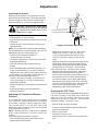
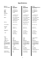
1
Professional G Series
Owner/Operator Manual
987
SERIES
M O DELS
070 - Professional G
071 - Professional G
072 - Professional G
08468700C Rev. 2/99
Supercedes 08468700,A,B
Printed in USA
A Message to Gravely Customers . . .
Welcome to the world of Gravely equipment. We are
pleased that you have purchased the best tractor
available. The care you give your Gravely tractor will
determine the satisfaction and service life you will
obtain from it. Use this manual as your guide. By
observing the instructions and suggestions in this
manual, your Gravely tractor will serve you well for
many years.
and is ready and able to serve you. If service is
required, be prepared to supply the service person
with the Model and Serial Number of the tractor, as
well as a full description of the problem encountered.
NOTE: The descriptions and specifications
contained in this manual were in effect at the time the
manual was approved for printing. Gravely reserves
the right to discontinue models without notice and
without incurring obligation. The tractor described
within this manual may not be identified as either
standard or optional and the various illustrations may
not be applicable to your particular unit. If you have
questions, always check with your Gravely dealer.
Your Gravely dealer will be happy to supply any
service or advice which may be required to keep your
Gravely tractor operating at peak efficiency. The
Dealer stocks genuine Gravely parts and lubricants;
manufactured with the same precision and skill as the
original. A factory trained staff is kept well informed
on the best methods of servicing Gravely equipment
Safety Alert Symbol and Notations
The following safety notations are used throughout
this manual to call attention to special information or
operating procedures. Understand the message in
each notation and be alert to unsafe conditions and
the possibility of personal injury.
DANGER: Indicates an imminently
hazardous situation that, if not avoided,
will result in death or serious injury.
WARNING: Indicates a potentially
hazardous situation that, if not avoided,
could result in death or serious injury.
NOTE: A NOTE points out general reference
infor mation regarding proper operation and
maintenance practices.
CAUTION: Indicates a potentially
hazardous situation that, if not avoided,
may result in minor or moderate injury.
It may also be used to alert against
unsafe practices.
IMPORTANT: An IMPORTANT statement indicates
specific procedures or information that is required to
prevent damage to the machine or its attachments.
This safety alert symbol is used to
attract your attention PERSONAL
SAFETY IS INVOLVED! When you see
this symbol - BECOME ALERT - HEED
ITS MESSAGE.
WARNING
The engine exhaust from this product
contains chemicals known to the State
of California to cause cancer, birth
defects or other reproductive harm.
OL4030
i
Contents
Models
Safety Alert and Notations . . . . . . . . . . . . . . . . . . .i
Safety Precautions . . . . . . . . . . . . . . . . . . . . . . . .2
Safety Decals . . . . . . . . . . . . . . . . . . . . . . . . . . . .4
Controls and Features . . . . . . . . . . . . . . . . . . . . . .5
Operation . . . . . . . . . . . . . . . . . . . . . . . . . . . . . . . .6
Lubrication and Maintenance . . . . . . . . . . . . . . . .9
Adjustments . . . . . . . . . . . . . . . . . . . . . . . . . . . . .12
Storage . . . . . . . . . . . . . . . . . . . . . . . . . . . . . . . .15
Service Manual . . . . . . . . . . . . . . . . . . . . . . . . . .15
Trouble Shooting . . . . . . . . . . . . . . . . . . . . . . . . .16
Specifications . . . . . . . . . . . . . . . . . . . . . . . . . . .17
Attachments . . . . . . . . . . . . . . . . . . . . . . . . . . . . .19
Accessories . . . . . . . . . . . . . . . . . . . . . . . . . . . . .20
Warranty . . . . . . . . . . . . . . . . . . .Inside Back Cover
Model 987070
16 HP Briggs & Stratton, Hydraulic Lift
Model 987071
13.5 HP Robin, Manual Lift
Model 987072
20.5 HP Robin, Hydraulic Lift
Note: All references to “Left”, “Right”, “Front” and
“Rear” are given from operator’s position.
Publications and Service Parts List
Order the following parts through your Dealer:
Specific Model and Serial Numbers are on a label
located on the frame of your tractor and on a label
located on the product registration form. Record
those numbers below and transfer the label from the
product registration to place indicated below. Use
these numbers whenever parts or service is required.
Model Number
Serial Number
Part No.
08471600
00026793
04202200
21527400
21527000
21527300
08811700
21526900
08904651
08861651
03498451
07219600
07219700
07226600
07226700
TRANSFER
MODEL SERIAL
LABEL FROM
PRODUCT
REGISTRATION
©Ariens Company - All Rights Reserved
1
Qty.
1
1
1
1
1
1
1
1
3
3
3
1
1
1
1
Description
Parts Manual
Service Manual
Battery
Air Cleaner (Robin EH64)
Oil Filter (Robin EH64)
Air Cleaner (Robin EH41)
Fuel Filter
Spark Plug (Robin)
Blade-60”
Blade-50”
Blade-40”
V-Belt-60”
V-Belt-60”
Belt-50” Mowerdrive
Belt-40” Mowerdrive
Safety Precautions
Safe Operation Practices For Ride-On
Mowers
roadways or drives. Follow traffic laws when
operating on or near a road.
Failure to observe the following safety instructions
could result in serious injury or death. Your complete
and unimpaired attention is required at all times.
Purchaser must give these instructions to the people
operating and maintaining this tractor.
Use extra care when loading or unloading the
machine into a trailer or truck. When handling
equipment connect the chassis to the transporting
vehicle. Never connect from control levers, rods, or
like items that could be damaged.
General Operation
Use only attachments or accessories designed for
your unit. See your Gravely Dealer.
Read, understand, and follow all instructions in this
owners manual, the engine manual, the attachment
manual and on the machine before starting.
Wear sturdy footwear. Do not operate tractor
barefoot or when wearing open sandals or canvas
shoes. Do not wear loose clothing that may get
caught in rotating parts of unit. Wear hand, head, ear
and eye protection.
Only allow responsible adults, who are familiar with
the instructions, to operate the machine.
Clear the area of objects such as rocks, toys, wire
etc., which could be picked up and thrown by the
mower or other attachment.
Slope Operation
Be sure the area is clear of other people & pets
before operating. Stop machine if anyone enters the
area. The operator is responsible for the safety of
bystanders.
Slopes are a major factor related to loss-of-control
and tip-over accidents, which can result in severe
injury or death. All slopes require extra caution. If
you cannot back up the slope of it you feel uneasy on
it, do not operate on it.
Before starting place the PTO lever in “Off” position
and the gear shift lever in the neutral “N” position.
Operate up and down slopes, not across. Do not
operate on steep slopes.
Never carry passengers.
Remove obstacles such as rocks, tree limbs, etc.
from the area of operation.
Operate only from operators position, on the seat.
Watch for holes, ruts, or bumps. Uneven terrain could
overturn the machine. Tall grass or deep snow can
hide obstacles.
Do not operate in reverse unless absolutely
necessary. Always look down and behind before and
while backing.
Use slow speed. Choose a low ground speed so that
you will not have to stop or shift while on the slope.
Engage the directional control pedal slowly.
Be aware of the attachment discharge direction and
do not point it at anyone. Do not operate without
either the entire attachment or the guarding in place
and functioning properly.
Follow the manufacturer’s recommendations for
wheel weights or counterweights to improve stability.
Slow down before turning to prevent tipping or loss of
control.
Use extra care with grass catchers or other
attachments. These can change the stability of the
machine. Use only approved hitch points.
Never leave a running machine unattended. Always
turn off attachment, set parking brake, stop engine,
move shift control to first gear position, and remove
keys to prevent unauthorized use before dismounting.
Limit loads to those you can safely control.
Keep all movement on the slopes slow and gradual.
Do not make sudden changes in speed or direction.
Turn off power to attachment when not in use.
Avoid starting or stopping on a slope. If tires lose
traction, disengage attachment power and proceed
slowly straight down the slope. If you must stop when
going up the slope and can not safely back down,
disengage the PTO, release the direction control
pedal, and depress the brake pedal. Then place the
gear selector in low speed and slowly release the
brake pedal, while slowly engaging the direction
control pedal.
Disengage attachment clutch, stop engine, remove
key and wait for moving parts to stop before leaving
operators position for any reason such as removing,
cleaning, servicing, or unclogging the attachment.
Operate only in daylight or good artificial light.
Do not operate the machine while under the influence
of medication, alcohol or drugs. Safe operation of
this equipment requires your complete and
unimpaired attention at all times.
Watch for traffic when operating near or crossing
2
Safety Precautions (Continued)
Children
Never tamper with safety devices. Check their proper
operation regularly. See page 7 for operatorpresence control check. If safety interlock is not
functioning properly do not operate the tractor. Have
repaired prior to use.
Tragic accidents can occur if the operator is not alert
to the presence of children. Children are often
attracted to the machine activity. Never assume that
children will remain where you last saw them.
Keep machine free of grass, leaves or other debris
build up. Clean up oil or fuel spillage. Allow machine
to cool before storing.
Keep children out of the area of operation and under
the watchful care of another responsible adult.
Be alert and turn machine off if children enter the
area.
Before and when backing, look behind and down for
small children.
Stop and inspect the equipment if you strike an object
or if their is a sudden change in the sound or
vibration of the equipment. Repair any damage
before restarting.
Never carry children. They may fall off and be
seriously injured or interfere with safe machine
operation.
Never make adjustments or repairs with the engine
running or when engine and exhaust parts are hot
from operation.
Never allow children to operate the machine.
Grass catcher components are subject to wear,
damage, and deterioration, which could expose
moving parts or allow objects to be thrown.
Frequently check components and replace, with
manufacturer’s recommended parts, when necessary.
Use extra care when approaching blind corners,
shrubs, trees, or other objects that may obscure
vision.
Service
Do not change engine governor setting or over speed
the engine.
Mower blades are sharp and can cut. Wrap the
blade(s) or wear gloves, and use extra caution when
servicing them.
Replace damaged or worn out muffler immediately.
Continued use could result in fire or explosion.
Check brake operation frequently. Adjust and service
as required.
Use extra care in handling gasoline and other fuels.
They are flammable and vapors are explosive.
Refer to Storage Section of this owners manual if unit
is to be stored for extended period.
A.
Use only an approved container.
B.
Never remove gas cap or add fuel with the
engine running. Allow engine to cool before
refueling. Do not smoke. Wipe off any spilled
gasoline and allow vapors to dissipate before
starting engine.
Use only Gravely accessories, attachments and
replacement parts. Replace parts that become
damaged or lost.
C.
Do Not
Do not turn on slopes unless necessary, and then,
turn slowly and gradually downhill, if possible.
Replace fuel tank cap and container cap
securely.
D.
Never refuel the machine indoors.
E.
Never store the machine or fuel container inside
where there is an open flame, such as in a water
heater. Allow engine to cool before storing in
any enclosure.
Do not operate near drop-offs, ditches, or
embankments. The tractor could suddenly turn over if
a wheel is over the edge of a cliff or ditch, or if an
edge caves in.
Do not operate on wet grass. Reduced traction could
cause sliding.
Do not try to stabilize the machine by putting your
foot on the ground.
Never run a machine inside a closed area. Exhaust
fumes contain carbon monoxide, an odorless and
deadly gas.
Do not use grass catcher on steep slopes.
Keep nuts and bolts, especially blade attachment
bolts, tight and keep equipment in good condition.
3
Safety Decals
ALTERNATOR ELECTRICAL SYSTEM
CAUTION
12 VOLT NEGATIVE GROUND
D O N O T R E V E R S E B AT T E RY
CONNECTIONS. DISCONNECT
R E G U L ATO R W H E N W E L D I N G
ON EQUIPMENT OR QUICK
C H A R G I N G B AT T E RY.
DO NOT OPERATE UNLESS
ALL GUARDS, SHIELDS AND
COVERS ARE IN PLACE
PJ0330
Hydraulic Lift Models
Manual Lift Models
UP
CONFORMS TO ANSI B71.4 SAFETY
STANDARD COMMERCIAL TURF CARE
EQUIPMENT.
CONFORMS TO ANSI B71.4 SAFETY
STANDARD COMMERCIAL TURF CARE
EQUIPMENT.
N
HOLD
DOWN
SAFETY FIRST
HIGHER
POSITION
RELEAS
E
LOWER
POSITION
LIFT RANGE
CONTROL
DIRECTION
CONTROL
READ THE OPERATORS MANUAL BEFORE
OPERATING OR DOING MAINTENANCE
ON THIS EQUIPMENT.
KEEP ALL GUARDS AND SHIELDS IN POSITION.
NEVER PERMIT CHILDREN TO OPERATE THIS
EQUIPMENT.
NEVER PERMIT PERSONS OTHER THAN THE
OPERATOR TO RIDE ON THIS EQUIPMENT.
LOOK FOR PERSONS AND HAZARDS.
BEFORE LEAVING THE OPERATOR POSITION
- PUT THE PTO CONTROL LEVER IN THE OFF
POSITION.
- REMOVE THE IGNITION KEY.
- LOWER THE ATTACHMENT.
- SET THE BRAKE LOCK FOR PARKING.
HI
SAFETY FIRST
FORWARD
N
REVERSE
3
DIRECTION CONTROL
READ THE OPERATORS MANUAL BEFORE
OPERATING OR DOING MAINTENANCE
ON THIS EQUIPMENT.
KEEP ALL GUARDS AND SHIELDS IN POSITION.
NEVER PERMIT CHILDREN TO OPERATE THIS
EQUIPMENT.
NEVER PERMIT PERSONS OTHER THAN THE
OPERATOR TO RIDE ON THIS EQUIPMENT.
LOOK FOR PERSONS AND HAZARDS.
BEFORE LEAVING THE OPERATOR POSITION
- PUT THE PTO CONTROL LEVER IN THE OFF
POSITION.
- REMOVE THE IGNITION KEY.
- LOWER THE ATTACHMENT.
- SET THE BRAKE LOCK FOR PARKING.
FORWARD
N
REVERSE
4
HI
3
4
ON
WARNING
ON
WARNING
DO NOT SHIFT GEAR
OR RANGE SELECTOR
DO NOT SHIFT GEAR
N
UNLESS VEHICLE IS
OR RANGE SELECTOR
N
STOPPED AND
UNLESS VEHICLE IS
DIRECTION CONTROL
STOPPED AND
LEVER IS IN NEUTRAL.
DIRECTION CONTROL
N
LEVER IS IN NEUTRAL.
N
OFF
LO
1
2
OFF
LO
PTO
CONTROL
LEVER
GEAR
SELECTOR
RANGE
SELECTOR
UNLOCK
TO USE THE BRAKE LOCK
STOP
LOCK
THE ENGINE WILL NOT START
UNLESS:
THE PTO CONTROL IS IN THE OFF
POSITION.
THE DIRECTION CONTROL IS IN THE
N POSITION.
PTO
CONTROL LEVER
GO
BRAKE LOCK FOR PARKING
1. PUSH THE BRAKE PEDAL
DOWN TO STOP.
2. PUT THE BRAKE LOCK LEVER
IN THE LOCK POSITION.
3. PUSH THE BRAKE PEDAL DOWN
AND PUT THE BRAKE LOCK
LEVER IN THE UNLOCK
POSITION TO UNLOCK THE
BRAKE.
1
UNLOCK
TO USE THE BRAKE LOCK
STOP
LOCK
THE ENGINE WILL NOT START
UNLESS:
THE PTO CONTROL IS IN THE OFF
POSITION.
THE DIRECTION CONTROL IS IN THE
N POSITION.
077253
2
GEAR
SELECTOR
RANGE
SELECTOR
GO
BRAKE LOCK FOR PARKING
1. PUSH THE BRAKE PEDAL
DOWN TO STOP.
2. PUT THE BRAKE LOCK LEVER
IN THE LOCK POSITION.
3. PUSH THE BRAKE PEDAL DOWN
AND PUT THE BRAKE LOCK
LEVER IN THE UNLOCK
POSITION TO UNLOCK THE
BRAKE.
077254
4
Controls and Features
1
8
2
3
11
10
9
4
12
7
5
6
13
PJ0340
14
15
16
PJ0350
1.
2.
3.
4.
5.
6.
7.
8.
Ammeter
Throttle Control
Choke Control
Direction Control Pedal
Gear Selector
Range Selector
PTO Control
Warning Light (Oil Pressure)
9.
10.
11.
12.
13.
14.
15.
16.
Hourmeter (side of panel)
Attachment Lift Switch
Ignition Switch
Brake Pedal
Brake Lock Lever
Release Button
Manual Lift Lever
Lift Range Control
Figure 1: Control and Feature Locations
5
Operation
NOTE: Read the tractor and attachment(s) manuals
before operating the equipment. Operate the tractor
only from the operator’s position on the seat. Service
the tractor and attachment before operating.
N
1
FORWARD
N
REVERSE
Gear Selector
4
3
2
Direction Control Pedal
The direction control pedal controls the
movement of the tractor. Push the pedal
forward and lock over center to go forward.
Push the pedal back to move the tractor
backwards (Figure 1).
Attachment Lift Switch
(Hydraulic Model)
UP
N
HOLD
The attachment lift switch is used to raise
and lower the attachment. The lift switch is
located on the instrument panel. Move the switch up
to raise, and down to lower the attachment.
DOWN
Range Selector
The range selector has two operating positions. The
forward (“HIGH”) position is the fast gear. The
rearward (“LOW”) position is the slow gear (Figure 1).
Ammeter
The ammeter indicates the condition of the charging
system. Normal operation will show the indicator
needle slightly to the “Plus” side of zero.
Throttle Control
The throttle lever (Figure 1) is used to
control the engine speed. To increase the
engine speed, move the lever up to the
“FAST” position. To decrease the engine
speed, move the lever down to the
“SLOW” position.
Brake Pedal
Pushing the brake pedal down will stop the tractor
and return the direction control pedal to “NEUTRAL”.
Use the brake pedal for sudden stops and for holding
the tractor on slopes.
Brake Lock Lever
Choke Control
UNLOCK
The choke control is used to choke a cold
engine for starting. The choke control is
located on the instrument panel (Figure 1).
Pull the choke out to the “ON” position to
choke the engine. When the engine is warm, move
the control to the “OFF” position.
STOP
LOCK
GO
To lock the brake for parking, depress the
brake pedal and pull back on the brake
lock lever. To release, push on the pedal
and move the lock lever forward.
PTO Control
To power an attachment, push the PTO
control forward to “ON”. To stop an
attachment, pull the PTO control rearward
to “OFF”. The operator must be in the
tractor seat to operate the PTO. If the operator
leaves the seat while the PTO control is in the “ON”
position, the engine will stop.
ON
Hourmeter
OFF
The hourmeter (on some models) shows total time
which the ignition switch has been in the “ON”
position (Figure 1).
Fuse
All models have a fuse to protect the electrical
system. The fuse is located in the wire harness.
Warning Light
The tractor is equipped with a warning light to alert
the operator in the event there is a problem with the
engine. The warning light is located on the upper left
side of the instrument panel. See Figure 1.
Ignition Switch
STOP
The gear selector has four operating
positions (Figure 1). See specifications for
ground speeds produced in each gear.
RUN
The ignition switch is operated with a
removable key. The switch has three
positions: “Off”, “On” and “Start”.
To start the engine, the key must be in the
“Start” position. Once the engine has started release
the key and it will return to the run position. To stop
the engine, turn the key to the “Off” position.
START
6
Operation
NOTE: The light is activated when there is a loss of
oil pressure. If the light comes on while operating the
tractor, stop the tractor and engine as quickly as
possible and check the engine oil level.
To let an attachment follow the ground:
• Move the switch to the “down” position. When the
attachment reaches the ground, hold the switch in
the “down” position for approximately 1/2 second
before releasing the switch.
To check to see if the light is operating correctly, turn
the ignition switch to the “ON” position. The light
should glow red.
Before Starting the Engine
Be sure that the tractor and engine have been
properly serviced and maintained.
NOTE: The engine must have been off for at least
five minutes prior to performing this test.
Operator Presence Control
Correct Operating Speeds
The operator must be sitting in the seat to allow
operation of the power take off (PTO) or traction
drive.
WARNING: On rough and sloping
ground and when mowing and trimming
near buildings, trees, and other
obstructions, use a slow ground speed.
CAUTION: The operator presence
control is intended to stop the engine
whenever the operator is not seated
and the PTO and direction control
pedal are not in the disengaged (PTO Off, direction control pedal - Neutral)
positions. Test this system each time
the tractor is operated. If this system
does not function as described do not
operate until repairs are made. NOTE:
Engine must not start unless PTO is
disengaged and direction control pedal
is in neutral.
NOTE: Most attachments, especially rotary mowers
and snowblowers, perform best when operated at full
engine speed. Proper ground speed is determined
by power limitations, the type of terrain, the quality
requirements of the job being perfor med,
obstructions, hazards, etc.
Using the Attachment Lift Systems
Manual or hydraulic lift systems are used to raise and
lower attachments. Either can hold an attachment in
position or let it follow the ground.
Using the Manual Lift System
To hold an attachment in position:
• Lift the attachment to the raise position.
• Lift the lift range control and slide it to the desired
position.
• Lower the attachment. The lift lever will stop
against the lift range control. If the attachment is
not in the desired position, repeat the first two
steps.
Starting and Stopping the Engine
To start the engine:
• The direction control pedal must be in “NEUTRAL”
position and the PTO control must be at “OFF”
position.
• Put the key in the ignition switch.
• Move the throttle lever to a middle position.
• If the engine is cold, move the choke lever to “ON”.
If the engine is warm, the choke lever should be at
“OFF”.
• Turn the ignition key to “START”. When the engine
starts, move the choke lever slowly to “OFF”. If the
engine does not start in five seconds, release the
key for a few seconds and then repeat. If the
engine does not start within five tries see section 6
for instructions.
To let an attachment follow the ground:
• Move the lift range control to the lowest position.
• Lower the attachment to the ground.
Using the Hydraulic Lift System
To hold an attachment in position:
• Lift the attachment by moving switch to the “up”
position until the attachment is fully raised.
• Lower the attachment to the desired position by
moving switch to the “down” position.
• When the attachment reaches the desired position,
release the switch. The attachment will be held in
that position.
CAUTION: Do not keep starter running
for over 15 seconds. Do not run the
starter for more than 15 seconds in any
one minute.
7
Operation (Continued)
To stop the engine:
• Move the throttle lever to “SLOW” and idle with the
PTO control disengaged for approximately 15
seconds.
the direction control pedal. If the operator leaves the
seat with the direction control pedal in the “Forward”
position, the engine will stop.
• Turn the ignition switch of “OFF”.
To move in a reverse direction:
• Follow the first two steps above.
• Remove the key before leaving the tractor.
• Push down firmly on the bottom of the direction
control pedal. The control pedal does not lock into
a reverse position. You must continue to push down
firmly to continue reverse travel. The pedal will
return to “Neutral” upon release.
Operating the Transmission
Use slow engine and transmission speeds until you
know how to operate the tractor safely.
DO NOT SHIFT TRANSMISSION GEARS
WHILE THE FORWARD OR REVERSE
CLUTCHES ARE ENGAGED OR THE
TRACTOR IS MOVING. This will damage
the gears. Always place the direction
control pedal in “NEUTRAL” and bring
the tractor to a complete stop before
moving the gear or range selectors.
To move in a forward direction:
• Start the engine and move the throttle to give the
desired engine speed.
• Put the range and gear selectors in the positions
that will produce the desired speeds. See section 7
for ground speeds produced.
• Move the direction control pedal forward. As the
tractor increases speed, push the pedal until it
locks into position. If the pedal is not pushed all the
way forward, slippage can damage the forward
clutch. USE CAUTION WHILE LEARNING TO
OPERATE THE DIRECTION CONTROL PEDAL.
NOTE: The operator must be in the seat to operate
8
Lubrication and Maintenance
Filling The Fuel Tank
Never operate the engine when the oil level is below
the low mark on the dipstick. See the engine manual
for the type of oil, oil change, etc. Never operate the
engine when the oil level is below the low mark on
the dipstick. See the engine manual for air cleaner
maintenance instructions.
WARNING: Use caution with fuel. Fuel
is very flammable. Keep fuel in a clean
and tight container. Keep fuel away
from fire or heat. Never put fuel in the
fuel tank while the engine is running or
hot. Clean up any spilled fuel before
starting the engine.
Control Linkage Lubrication
Every 25 hours of operation put a drop of engine oil
on the pivots of the throttle lever, the direction control
lever, the gear shift lever, the PTO control, and range
shift handle.
Add fuel to the fuel tanks as needed. See your
engine manual for the correct type and grade of fuel.
Battery Service
Put the unit in an open area. Stop the engine and
lock the brake. Clean the fuel cap and the area
around the fuel cap to prevent dirt from entering the
fuel tank. See Figure 2. Remove the cap from the
fuel tank. Fill the fuel tank. Be careful not to spill the
fuel. Install the cap on the fuel tank and tighten.
Clean up any spilled fuel before starting the engine.
The tractor is equipped with a low maintenance
battery. Check the fluid level every 200 hours or at
the end of the year (Figure 2). Keep the battery clean.
If acid is on the outside of the battery or the electrical
connections are corroded, clean the outside of the
battery with a water and baking soda solution.
Anytime the battery cables are to be disconnected,
remove the negative (-) (ground) cable first. When
replacing the battery cable connect the positive (+)
cable first. Anytime the batter y cables are
disconnected, the cable clamps and the battery post
or connection should be cleaned until shiny. There
are brushes make to clean the clamps and battery
posts.
4
1
3
Fastener Check
Check all fasteners after 25 hours of operation to
make sure that they are tight. Replace any fastener
that is missing.
General Lubrication
There are seven grease fittings to be greased at 25hour intervals. Clean the fittings before attaching the
grease gun. Use a high quality lithium base grease.
Add grease until it appears at the ends of the
bearings. The locations of the seven fittings are:
• On the direction control pedal.
2
PJ0360
1.
2.
3.
4.
Fuel Cap
Negative Battery Cable
Battery
Positive Battery Cable
• On the front axle at each king pin.
• On the front axle (Figure 3).
Figure 2: Battery Connectors
• On the steering mechanism (Figure 4).
Apply motor oil to all pin connections, pivot points and
areas where sliding occurs in the clutch,
transmission, PTO, and lift control systems every 25
hours.
Engine Maintenance
See the engine manual for maintenance instructions.
Check the air cleaner and engine oil daily. Check the
cooling system every 25 hours. Clean all of the grass
and other material from the cooling fins and intake
screen of the engine. If necessary, remove the
engine shrouds to clean the engine. See the engine
manual for the type of oil, oil change, etc.
9
Lubrication and Maintenance (Continued)
4
3
5
1
2
1
PJ0370
1.
2.
3.
4.
5.
1. Grease Fitting on the Front Axle
Figure 3: Steering Axle Pivot
Checking the Engine Oil
3
PJ0380
Grease Fittings for the Steering Arms
Grease Fittings for the Steering Columns
Adjusting Bolt
Lock Nut
Adjusting Nut
Figure 4: Steering Arms
Check the engine oil level daily. Never operate the
engine with the oil level below the low mark on the
dipstick.
See your engine manual for oil
specifications and oil filter service instructions.
• Clean the areas around the dipstick and
drain plug.
To check the oil level:
• Put an open top container that will hold four quarts
under the drain plug.
• Remove the dipstick.
• Clean around the dipstick to prevent dirt from
entering the tube.
• Remove the drain plug.
• Remove the dipstick and wipe off the oil.
• Allow the engine to drain completely.
• Put the dipstick back in place. Be sure it is all the
way down.
• Clean and reinstall the drain plug.
• Remove the oil filter (some models), clean the oil
filter port and install a new oil filter according to the
instructions on the oil filter.
• Remove the dipstick again and note oil level.
• Add oil, if needed. Do not overfill.
• Fill with new oil to the “Full” mark on the dipstick.
• Put the dipstick back in place. Be sure it is all the
way down.
• Replace the dipstick. Lower the rear fender.
Changing the Engine Oil
• Start the engine and check for leakage at the drain
plug. Tighten the plug if leakage occurs.
• Read your engine manual for recommended
change schedule.
Checking the Battery Fluid
Check the battery fluid every 200 hours. Use caution
and wear eye protection when checking the battery.
To check the battery:
• Move the tractor to a level area. Lock the brake.
• If the engine is cold, let it run for 5 minutes.
• When the engine is warm, stop it and raise
the rear fender.
• Clean the top of the battery.
• Lift the filler caps.
• If the fluid level is below the split rings in the filler
tube, add distilled water. Do not fit above the split
ring. Do not use a metal funnel.
WARNING: Engine muffler and other
parts are hot.
• Reinstall the filler caps. Push them all the way
down.
10
Lubrication and Maintenance (Continued)
Checking the Fasteners
Check the transmission oil level every 200 hours or
twice a year, whichever comes first. If leakage is
observed, check more frequently. The fill tube and
check plug are shown in Figure 5.
Every 25 hours, or any time looseness of parts,
rattles, or excess noise and vibration are noted,
check all fasteners. Look for loose or missing
fasteners. Make sure all bolts, screws, nuts, pins,
snap rings, and cotter pins are in the correct position
and replace any that are missing.
To check the transmission oil level:
• Move the tractor to a level area. Stop the engine
and lock the brake.
Checking the Air Intake Screen
• Raise the rear fender. Locate and clean the check
plug on the left side of transmission and remove it.
Check the air intake screen on the engine each day.
Remove any grass, dirt, or debris that may have
accumulated on it. The air intake screen must be
kept clean.
• The oil level is correct when oil is at the bottom of
the hole.
• If the level is correct, reinstall and tighten the plug.
If the level is low, add oil. See Specification
Section for recommended lubricant specifications.
Checking the Cooling System
Check the cooling system for signs of the collection of
grass and debris in the engine cooling fins every 25
hours or more often when operated in dir ty
conditions. See your engine manual for instructions.
To add oil:
• Remove the fill tube cap. Add oil until it reaches
the bottom of the check plug hole.
• Reinstall and tighten the fill tube cap and check
plug.
Checking the Air Cleaner
Check the air cleaner each day. See your engine
manual for instructions.
Changing the Air Cleaner Element
Replace the air cleaner element at the correct
intervals. See your engine manual for instructions.
Checking the Transmission Oil
1
2
PJ0390
1. Fill Tube
2. Check Plug
Figure 5: Checking Transmission Oil
11
Adjustments
Adjusting the Brakes
Brake service is required if the brake does not stop
and hold the tractor effectively. The brake should be
effective enough to cause the rear wheels to slide if
applied suddenly on a concrete or asphalt surface.
CAUTION: Replace the brake band
when the lining is as thin as the ignition
key. Replace the brake drum if it is
visibly worn or rough.
MEASURE FREE TRAVEL HERE
To adjust the brake:
• Stop the tractor on a level surface.
CLEARANCE
• Stop the engine and block the wheels so the tractor
cannot roll.
• Loosen the jam nut and remove the clevis pin (at
the brake band)
Figure 6: PTO Clutch Adjustment
• Raise the rear fender.
NOTE: Do not adjust the brake rod on the left hand
side which attaches to the brake pedal. This rod is for
adjusting the direction control pedal only.
• Measure the clearance in the slot. The correct
clearance is .030 inch (.76mm) to .060 inch
(1.5mm) for the forward clutch and .010 inch
(.25mm) to .030 inch (.76mm) for the reverse
clutch.
• Turn the clevis clockwise to tighten or
counterclockwise as needed.
• To check the adjustment, reconnect the clevis and
brake band with the pin.
• Adjust the bolts which go through the flange on the
axle bearing retainer so that the forward-reverse
clutch springs are straight up and down when the
clutches have zero clearance. Lock the bolt in
place with the jam nut. Loosen the jam nut which
holds the slide rod bushing in place. Adjust the
bushing on the slide rod until the clearance is
correct. Lock the bushing in place with the jam nut.
• Push the direction control pedal all the way
forward.
• Push the brake pedal by hand while watching the
motion of the brake band. The brake is correctly
adjusted when the band becomes tight on the drum
as the direction control pedal moves to “Neutral”. If
the band it tight before the pedal moves to
“Neutral”, the brake is too tight. If too tight or too
loose, repeat steps 4, 5, 6 and 7 until the correct
adjustment is obtained.
• Install the cotter pin in the clevis pin and tighten the
jam nut.
• Lubricate the clutch once each season. Remove
the clutch and apply a film of high quality lithium
base grease to the splined clutch shaft. While the
clutch is off, check the lining wear. If the lining has
worn near the rivet heads, replace the lining.
Readjust the clutch as described above.
• Check the effectiveness of the brake while
operating the tractor.
Adjusting the PTO Clutch
The PTO clutch should be adjusted whenever there is
less than .5 inches of free travel in the clutch lever
when it is in the “On” position. See Figure 6 to see
where this free travel is measured. The free travel
should be between .5 inch and 1.0 inch.
Adjusting the Forward and Reverse
Clutches
The forward and reverse clutches must be checked
every 100 hours. If the lining has worn to a thickness
of less than 0.150 inch (3.8mm), replace the lining.
The forward clutch is on the right side of the
transmission and the reverse clutch is on the left side
of the transmission (Figure 5).
NOTE: Damage will occur if the tractor is operated
with a lining thickness of less than 0.150 inch
(3.8mm).
Inspect and adjust the clutches as follows:
• Stop the engine and place the direction control
pedal in the “Neutral” position.
• Stop the engine and lock the brake.
• Loosen the bolts holding the switch bracket and
push the bracket down.
• Raise the rear fender.
• Push the PTO lever to “On”.
• Disconnect the PTO control from the transmission
lever.
12
Adjustments (Continued)
• On 13.5 HP and 16 HP engine units, loosen the
jam nuts on the tie rods and disconnect the outside
ball joint. Rotate the front tires by hand so that the
distance between the front centerline of the tire is
1/8” to 1/2” less than the Distance between the rear
centerline. Adjust the tie rods so that the ball joint
can be connected to the tie rod arm without moving
the tire and so that the tie rods are the same length.
Tighten the jam nuts.
• Turn the control rod to change the free travel. Each
turn will change it by about .25 inch. Turn clockwise
to increase and counterclockwise to decrease the
free travel.
• Reconnect the control rod to the transmission lever.
Check for correct free travel. Repeat above three
steps if necessary.
• Put the PTO control in the “Off” position.
• Move the switch bracket up until the switch closes
(makes a circuit). Tighten the switch bracket
hardware.
• On 20.5 HP units, loosen the jam nuts on the
tie rods and rotate the tire rod tube so that the front
centerline of the tire is 1/8” to 1/2” closer than the
rear centerline and so that the tie rods are the
same length. Tighten the jam nuts.
CAUTION: Make sure that the PTO
control assembly does not rest on the
switch body.
Servicing the Spark Plug(s)
To clean or change a spark plug:
• Stop the engine, lock the brake, and raise the seat
pan weldment.
Adjusting the Steering System
Adjustment of the steering gear is usually needed
whenever there is more than 2 inches of free play in
the steering wheel. To adjust the steering gear:
• Loosen the lock nuts on both adjusting bolts
(Figure 4).
• See your engine manual for further instructions.
Servicing the Hydraulic Lift
WARNING: Keep body and hands away
from pin holes or nozzles which eject
hydraulic fluid under pressure. Use
paper or cardboard and not hands to
search for leaks.
• Turn the steering wheel to the right as far as it will
go.
• Turn the adjusting nut on the left side adjusting bolt
clockwise with your fingers until it is tight. Then
back the nut off one fourth turn.
• Tighten the lock nut against the adjusting nut being
careful not to move the adjusting nut.
Be sure to stop the engine and put the attachment in
the down position before doing any work on hydraulic
parts.
• Turn the steering wheel to the left as far as it will
go.
WARNING: Make sure all hydraulic fluid
connections are tight and all hydraulic
hoses and lines are in good condition
before applying pressure to the system.
• Repeat the above two steps for the right side
adjusting nut.
• Check for tightness or backlash in the steering gear
through the full range of the steering wheel rotation.
There should be no noticeable tightness or
backlash in the rack and pinion mesh. If there is,
repeat above steps as required.
Upon completion of the steering gear adjustment,
recheck the steering wheel free play. If the free play
is still excessive, look for loose steering arms on the
king pins, loose or worn ball joints, or other signs of
wear. Tighten or replace as required.
Hydraulic fluid escaping under pressure may have
sufficient force to penetrate skin and cause serious
injury. Foreign fluid injected into the skin must be
surgically removed within a few hours by a doctor
familiar with this form of injury or gangrene may
result.
Check the hydraulic fluid level when the hydraulic lift
will not raise the attachment or leaks are observed.
Adjust the front wheel toe-in as follows:
To check the hydraulic fluid level:
• Rotate the steering wheel until the two steering arm
weldments are parallel to the frame side.
• Clean the area around the reservoir and cap.
• Remove the cap.
• The correct hydraulic fluid level is one inch from the
top of the reservoir. Add Dextron II ATF to maintain
this level.
13
Adjustments (Continued)
Adjusting the Range Selector
• Move the Hi-Lo shift lever as far as it will go in both
directions. Measure the distance between the lever
and the end of the slot. This distance should not be
less than 5/16”.
• Adjust the clevis so that the clearance between the
Hi-Lo shift lever and the control cover plate slot is
equal for both positions of the lever.
Adjusting the Seat
The seat has 4” of front-to-rear adjustment. To adjust
the seat, pull the adjustment lever out and move the
seat forward or backward. Release the lever and
ensure that the seat is locked into position.
14
Storage
Storing the Unit
Taking the Unit Out of Storage
• Do the daily and 25-hour maintenance, but do not
add gasoline.
• Refer to the engine manual and prepare the engine
for service.
• Clean the tractor. Paint or oil bare metal surfaces
to prevent rust.
• Charge the battery.
• Put fresh, clean gasoline in the fuel tank.
NOTE: Do not use harsh or abrasive cleaners on any
painted surface. Do not allow gasoline or oil to
remain on any silk screened surface.
• Refer to the engine manual and prepare the engine
for storage.
• Clean and charge the battery. Charge the battery
every three or four weeks while in storage.
• Place the PTO lever in “OFF” position.
• Store in a cool, dry place.
IMPORTANT: NEVER spray unit with water or store
unit outdoors to aid in prevention of rust or corrosion.
Water can seep into sealed bearings, which are
sealed against dirt and debris only, causing reduced
component life.
Service Manual
Service manuals are available for owners who wish to
perform some of their own maintenance and service
operations. Should a complete service manual be
desired, order under the following part number.
655 West Ryan Street
P.O. Box 157
Brillion, WI 54110-0157
When ordering parts always include the Model and
Serial Number of your unit to assure prompt service.
A parts manual is included in your literature package
to make ordering of service parts easier.
Professional G Series
Service Manual
Part No. 00026793
Tractor Model Number
Tractor Serial Number
Mail Request to:
Ariens Service
15
Trouble Shooting
1. No sound or motion when the ignition switch
is turned to the “Start” position.
5. Engine continues to run when the ignition
switch is rotated to the “Off” position.
PTO control in the “On” position.
Direction control pedal in the forward or reverse
position.
Blown fuse.
Discharged battery.
Starting solenoid damaged.
Loose battery cable(s).
Damaged time delay module.
Ground wire not connected.
Ignition switch failure.
6. Lights do not come on when the light switch
is moved to the “ON” position.
Light(s) burned out.
Defective light switch
Loose wire connections
Engine light alternator failure
Ignition switch failure.
2. When the ignition switch is turned to “Start”,
the solenoid “clicks” and the engine starter
motor does not operate.
7. Engine runs rough or stops after it gets hot.
Discharged battery.
Battery cable connector(s) corroded.
Starter damaged.
See Engine Service Manual.
Time delay failure.
3. When the ignition switch is turned to “Start”,
the starter operates but the engine does not
start.
8. Fuse blows when starting engine.
Defective solenoid.
Relay or relay connection(s)
Fuel tank empty.
Fuel valve turned off
Engine spark plug(s) fouled.
Engine failure -- see Engine Service Manual
9. Hydraulic lift will not lift attachment.
Hydraulic pump seals
Cylinder seals
Low fluid level
Hydraulic pump
Relief valve setting
Blown Fuse
4. Battery discharged.
Regulator-rectifier failure.
Fuse holder or battery.
Engine alternator failure.
Battery failure.
16
Specifications
Model No.
Description Name
987071
13.5 HP Robin
Manual Lift
987072
20.5 HP Robin
Hydraulic Lift
987070
16 HP Briggs & Stratton
Hydraulic Lift
Length
Width
Height
Weight
Wheelbase
82” (208.3 cm)
41.5” (105.4 cm)
51” (129.5 cm)
858 lbs.
82” (208.3 cm)
43.2” (109.7 cm)
51” (129.5 cm)
863 lbs.
82” (208.3 cm)
41.5” (105.4 cm)
51” (129.5 cm)
860 lbs.
Battery
12 Volt BCI Group
22F, 42 AMP Hr
12 Volt BCI Group
22F, 42 AMP Hr
12 Volt BCI Group
22F, 42 AMP Hr
Brakes
External Band Brake
on transmission,
individual rear wheel
brakes optional
External Band Brake
on transmission,
individual rear wheel
brakes optional
External Band Brake
on transmission,
individual rear wheel
brakes optional
Steering
Rack & Pinion
Rack & Pinion with
heavy tie rods
Rack & Pinion
Turning Radius
26.5” (67.3 cm)
26.5” (67.3 cm)
26.5” (67.3 cm)
Tire Sizes
Front
Rear
16 x 6.5 - 8
23 x 8.5 - 12
16 x 7.5 - 8
23 x 8.5 - 12
16 x 6.5 - 8
23 x 8.5 - 12
14-18 PSI
(97-124 kN/m2)
16-14 PSI
(69-97 kN/m2)
14-18 PSI
(97-124 kN/m2)
16-14 PSI
(69-97 kN/m2)
14-18 PSI
(97-124 kN/m2)
16-14 PSI
(69-97 kN/m2)
Robin
EH41
13.5
3300/1600
See Engine Manual
See Engine Manual
See Engine Manual
5.3 Gals. (20 Liters)
25 AMP
Robin
EH64
20.5
3300/1600
See Engine Manual
See Engine Manual
See Engine Manual
5.3 Gals. (20 Liters)
25 AMP
Briggs & Stratton
303447
16
3300/1600
See Engine Manual
See Engine Manual
See Engine Manual
5.3 Gals. (20 Liters)
25 AMP
Transmission
Oil Capacity
Transmission Type
6 Qt.
(5.7 Liters)
API Service
SC10W-30 Motor Oil
6 Qt.
(5.7 Liters)
API Service
SC10W-30 Motor Oil
6 Qt.
(5.7 Liters)
API Service
SC10W-30 Motor Oil
Hydraulic Type
Hydraulic Capacity
N/A
N/A
ATF Dextron II
1 Qt. (.9 Liter)
ATF Dextron II
1 Qt. (.9 Liter)
Tire Pressure
Front
Rear
Engine
Type
Model No.
HP
RPM Hi/Low
Engine Oil
Engine Oil Capacity
Fuel Specifications
Fuel Tank Capacity
Fuse
17
Specifications (Continued)
Ground Speeds (at 3600 rpm Engine Speed):
TRACTOR GROUND SPEEDS
FORWARD
Gear
"LO" Range
1
.5 mph (.8 km/hr)
2
.8 mph (1.2 km/hr)
3
1.1 mph (1.8 km/hr)
4
1.7 mph (2.7 km/hr)
R EVERSE
"HI" Range
"LO" Range
2.5 mph (4.0 km/hr) 1.1 mph (1.8 km/hr)
3.8 mph (6.1 km/hr)
1.7 mph (2.7 km/hr)
5.7 mph (9.2 km/hr)
2.5 mph (4.0 km/hr)
8.5 mph (13.7 km/hr) 3.8 mph (6.1 km/hr)
18
"HI" Range
Same
Same
Same
Same
Attachments
See your authorized Ariens dealer to add these additional attachments
to your Tractor.
88500600 - 50” Mower
88700300 - 60” Mower
88500400 - 40” Mower Deck
78700300 - Front Adaptor Kit Required
88501500 - 44” Power Brush
78700200 - Completing Kit Required
83300600 - 48” Sno Blower
88701100 - 48” Snow Dozer Blade
88701500 - Roll Over Protection
88703900 - Sunshade Kit
088700700 - Grass Catcher Blower
& Frame Assembly
833002 - 3 - Can Grass Catcher
Assembly
88501000 - Rotary Plow
78700300 - Front Adaptor Kit Required
19
Accessories
Enhance you Series G Tractor with these Gravely Accessories
Mowing Accessories
78500800
78700200
78700300
78501300
78501400
78700400
78700500
78700600
78700700
40” Mower Drive
Front Drive Kit
Front Adapter Kit
Front Anti-Scalp Roller
Rear Anti-Scalp Roller
Drive Kit For Kohler Engines
Boot Kit For 40” Mower
Boot Kit For 50” Mower
Boot Kit For 60” Mower
Garden Accessories
78701200
78700200
78700300
78503000
Liftable Rear Hitch
Front Drive Kit
Front Adapter Kit
Attachment Adapter Kit
Snow Removal Accessories
78701400
78700200
73500700
78701500
78701600
78701700
78701800
78701900
44” Power Brush Completing Kit
Front Drive Kit
Snowblower Drift Bar
Tire Chain (23 x 8:50) (Pair)
Tire Chains (23 x 10:50) (Pair)
Safety Light (Cab)
Glass Windshield (Cab)
Electric Wiper (Cab)
Miscellaneous Accessories
78700300
78702100
78702400
78702500
78702600
78705100
78705200
78707800
78703000
78707900
78506600
78506700
78705400
78506800
78506900
78707700
Front Adapter Kit
Lift Assist Kit
Front Wheel Weights (Pair)
Front Wheel Weights (Pair)
Rear Wheel Weights (Each)
Engine Guard
Tractor Cover
Arm Rest Kit
Forward/Reverse Lever Kit
Debris Basket
High Lift Blade Kit 40”
High Lift Blade Kit 50”
High Lift Blade Kit 60”
Sand Blade Kit 40”
Sand Blade Kit 50”
Electric Hydraulic Lift Kit
Be sure to always use genuine Gravely parts to keep your
tractor running like new.
20
Index
Accessories
20
Adjustments
Adjusting the Brakes
Adjusting the Forward and Reverse Clutches
Adjusting the PTO Clutch
Adjusting the Range Selector
Adjusting the Seat
Adjusting the Steering System
Servicing the Hydraulic Left
Servicing the Spark Plugs
12
12
12
12
14
14
13
13
13
Attachments
19
Controls and Features
Lubrication and Maintenance
Battery Service
Changing the Air Cleaner Element
Changing the Engine Oil
Checking the Air Intake Screen
Checking the Air Cleaner
Checking the Air Cleaner Element
Checking the Battery Fluid
Checking the Cooling System
Checking the Engine Oil
Checking the Fasteners
Checking the Transmission Oil
Control Linkage Lubrication
Engine Maintenance
Fastener Check
Filling the Fuel Tanks
General Lubrication
Models
Operation
Ammeter
Attachment Lift Switch
Before Starting the Engine
Brake Lock Lever
Brake Pedal
Choke Control
Correct Operating Speeds
Direction Control Pedal
Fuse
Gear Selector
Hourmeter
Ignition Switch
Operating the Transmission
Operator Presence Control
PTO Control
Range Selector
Starting and Stopping the Engine
Throttle Control
Using the Attachment Lift Systems
Warning Light
Safety Alert Symbol and Notations
5
9
9
11
11
11
11
11
10
11
10
11
11
9
9
9
9
9
1
21
i
Safety Decals
4
Safety Precautions
Children
General Operation
Service
Slope Operation
2
3
2
3
2
Service Manual
15
Specifications
17
Storage
Storing the Unit
Taking the Unit Out of Storage
15
15
15
Trouble Shooting
16
Warranty
6
6
6
7
6
6
6
7
6
6
6
6
6
8
7
6
6
7
6
7
6
Inside Back Cover
655 West Ryan Street • P.O. Box 157 • Brillion, WI 54110-0157 • 920-756-2141 • Fax: 920-756-4421
Ask Your Dealer For Information On
These Other Fine GRAVELY Products
• Professional Two-Wheel Tractors
• Professional Riding Tractors
• Pro Commercial Walk-Behind Mowers
• Promaster Commercial Front-Mount Riding Mowers
• Pro Zero-Turn-Radius Walk-Behind Mowers
• Promaster Zero-Turn-Radius Riding Mowers
• Professional Chippers
• Professional Vacuum