1
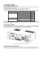
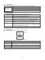
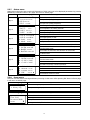
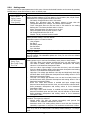
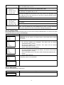
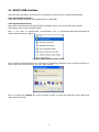
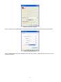
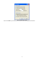
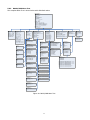
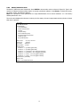
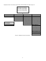
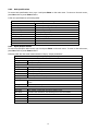
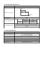
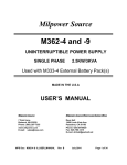
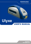
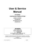
User Manual Outdoor UPS 2KVA Version: 1.0 Table Of Contents 1. ABOUT THIS MANUAL ...............................................................................................................................1 1.1. 1.2. Purpose .................................................................................................................................................1 Scope ....................................................................................................................................................1 2. SAFETY INSTRUCTIONS ...........................................................................................................................1 3. INTRODUCTION ..........................................................................................................................................2 3.1 3.2 3.3 4. INSTALLATION ............................................................................................................................................6 4.1 4.2 4.3 4.4 5. Line Mode Specifications ....................................................................................................................29 Battery Mode Specifications ...............................................................................................................30 Charger Mode Specifications ..............................................................................................................31 General Specification ..........................................................................................................................31 TROUBLE SHOOTING ..............................................................................................................................32 7.1 7.2 8. Switch on UPS in Line mode ................................................................................................................9 Switch the UPS from line mode to battery mode ..................................................................................9 Switch from battery mode to line mode ................................................................................................9 Switch off procedure .............................................................................................................................9 Operation the Control panel ................................................................................................................10 RS232/USB interface ..........................................................................................................................17 Optional SNMP card ...........................................................................................................................28 SPECIFICATIONS ......................................................................................................................................29 6.1 6.2 6.3 6.4 7. Unpacking and Inspection.....................................................................................................................6 Mounting the UPS .................................................................................................................................6 Mounting the PTS (Optional) ................................................................................................................6 Wiring ....................................................................................................................................................7 OPERATION.................................................................................................................................................9 5.1 5.2 5.3 5.4 5.5 5.6 5.7 6. System Architecture ..............................................................................................................................2 UPS Module ..........................................................................................................................................3 PTS Module (Optional) .........................................................................................................................4 For PTS Module ..................................................................................................................................32 For UPS Module .................................................................................................................................33 Appendix: Approximate Back-up Time Table ........................................................................................34 2 1. ABOUT THIS MANUAL 1.1. Purpose This manual contains important instruction that must be followed when install, service or maintain the product. Please read the instruction and drawings carefully before installations and operations. Keep this manual in a safe place for future reference. 1.2. Scope This manual provides safety and installation guidelines as well as information on tools and wiring. 2. SAFETY INSTRUCTIONS WARNING: This chapter contains important safety and operating instructions. Read and keep this manual for future reference. 1. 2. 3. 4. 5. 6. 7. 8. 9. 10. 11. 12. 13. Before using the unit, read all instructions and cautionary markings on the unit, the batteries and all appropriate sections of this manual. CAUTION --To reduce risk of injury, charge only deep-cycle lead acid type rechargeable batteries. Other types of batteries may burst, causing personal injury and damage. Do not disassemble the unit. Take it to a qualified service center when service or repair is required. Incorrect re-assembly may result in a risk of electric shock or fire. To reduce risk of electric shock, disconnect all wirings before attempting any maintenance or cleaning. Turning off the unit will not reduce this risk. CAUTION – Only qualified personnel can install this device with battery. NEVER charge a frozen battery. For optimum operation of this unit, please follow required spec to select appropriate cable size. It’s very important to correctly operate this unit. Be very cautious when working with metal tools on or around batteries. A potential risk exists to drop a tool to spark or short circuit batteries or other electrical parts and could cause an explosion. Please strictly follow installation procedure when you want to disconnect AC or DC terminals. Please refer to INSTALLATION section of this manual for the details. Battery breaker (60A) is provided as over-current protection for the battery supply. GROUNDING INSTRUCTIONS -This unit should be connected to a permanent grounded wiring system. Be sure to comply with local requirements and regulation to install this unit. NEVER cause AC output and DC input short circuited. Do NOT connect to the mains when DC input short circuits. Warning!! Only qualified service persons are able to service this device. If errors still persist after following troubleshooting table, please send this unit back to local dealer or service center for maintenance. 1 3. INTRODUCTION The battery backup system provides constant and reliable backup power to outdoor equipment. It consists of Uninterruptible Power Supply (UPS) System and optional Power Transfer Switch (PTS) that provide backup power when the line is unqualified. These components should be mounted inside an enclosure to provide protection from most weather conditions. 3.1 System Architecture Figure 1: Battery Backup System Block Diagram 2 3.2 UPS Module The UPS module provides utility power to load when line is qualified. And an automatic voltage regulator (AVR) is embedded to provide stable power to the load. It will instantly switch to emergency backup power during utility power failure or interruption. The front panel view is shown as below. Figure 2: Front Panel of UPS AC Input Terminal Block This terminal block is the UPS AC line power input. AC Input Breaker This circuit breaker is an on/off switch for the line power into the UPS that also provides input protection. It must be switched on for proper UPS operation. AC Output Terminal Block This terminal block is the UPS AC power output. AC Output Breaker This circuit breaker is a resettable protective thermal circuit breaker to protect UPS output from overload and short circuits. Input Contact To activate a programmable alarm by shorting this input contact. Dry Contact Six sets of dry contacts will energize when programmable event occurs. Internal Fan It’s to cool down inside temperature of the UPS. The fan is flexibly replaced for maintenance. GND This connector is permanent ground of the UPS. Battery Connector The battery connector is to connect external batteries. Mounting Bracket & Handle This part is for unit mounting on the size of 19’’ cabinet and for people moving unit conveniently. Battery Temperature Connector This is used to monitor battery temperature. The temperature probe connector must be plugged in UPS for normal operation. The other end should be firmly attached to the terminal of the battery. 3 External FAN Connector To provide DC Power (48Vdc, 3 Amp Max) to an optional 48Vdc fan. PTS Control Connector This connector provides power to control the PTS unit. Battery Breaker This over-current protection is used as an on/off switch for the battery power. It must be switched on for proper UPS operation. Battery Voltage Test Points The test points allow you to measure battery voltage. They accept 2 mm diameter test probe tips. The battery circuit breaker must be turned on before measuring voltage. CAUTION: The battery voltage test points are NEVER be used as a power outlet. Function Keys These buttons are used to operate and control the LCD panel. LCD Display Panel It shows the UPS information in four-line texts. Indicator LEDs Three LEDs show the information of output status, alarm and fault. USB Connector This is used to connect the UPS to the computer for remote control and monitoring. RS232 Connector A straight-through DB-9 to DB-9 connector cable can be connected in. It is used to connect the UPS to the computer for remote control and monitoring. Intelligent Slot (optional) This optional slot is for SNMP card insertion to communicate with UPS. The UPS can be monitored and controlled via a web browser or with SNMP protocols. 3.3 PTS Module (Optional) The Power Transfer Switch (PTS) shown below allows the UPS to be removed for service, replacement or maintenance without interrupting power to the outdoor equipment. Figure 3: Front Panel of PTS with terminal block AC Input Terminal Block The line input power is connected to the terminal block marked with “AC IN”. AC Output Terminal Block The output power is connected to the terminal block marked with “AC OUT”. 4 Switch UPS or bypass output can be selected by this switch. AC Output Breaker This circuit breaker marked with “OUTPUT’’ is a resettable protective thermal circuit breaker to protect the output from overloads and short circuits. AC Input Breaker This circuit breaker marked with “UPS INPUT’’ provides input power protection for the UPS. AC Output Receptacles These receptacles are ready to use for optional battery heating pads or a PC for maintenance. UPS Input Connector This “UPS IN” power cord is connected to AC input connector or terminal blocks on UPS. UPS Output Connector This “UPS OUT” power cord is connected to the AC output connector or terminal blocks on UPS. PTS Control Wiring The Black and Red PTS control wires are used to connect to PTS control connector on UPS. 5 4. INSTALLATION 4.1 Unpacking and Inspection Before installation, please remove the unit from its box carefully since the UPS is heavy. Follow the below guidelines to unpack and inspect the unit. 1. Select a suitable area for unpacking and be sure that nothing inside is damaged. 2. Store all the packing materials and boxes for possible equipment returns. 3. Inspect the package contents and make sure all standard items as well as purchased options are included. Standard Items Item Contents Quantity UPS UPS Unit 1 Manual 1 Temperature sensor cable 1 Mounting bracket 2 Screws for Mounting bracket 8 SNMP card (optional) 1 PTS (optional) PTS Unit 1 Fasteners 4 4. Compare the listed parts with the items you received. If the listed parts on your package does not match the items you received, or any items appear damaged, please immediately notify your carrier agent and the supplier who prepared your shipment. 4.2 Mounting the UPS The UPS unit can be placed on a shelf with no other parts needed. It can be rack mounted or secured to a shelf such as in an outdoor cabinet, with the mounting brackets shown in the following figure. The brackets and the screws to attach them to the UPS case are available as part of the standard packaging. Figure 4: UPS with Bracket for rack mounting 4.3 Mounting the PTS (Optional) The power transfer switch is designed and factory-installed with a 19" rack mounting bracket accessory shelf. It can be rack mounted or placed on a shelf. The fixing screws and washers are packaged as accessories of PTS. 6 Figure 5: PTS with Bracket for rack mounting 4.4 Wiring WARNING! All electrical wiring must be performed by a qualified electrician or trained personnel. Make sure the line power is off. Switch off all input and output circuit breakers on the UPS unit before making any electrical connections. 4.4.1 Wiring the UPS 1. Connect the temperature sensor to the UPS unit (Battery Temperature connector connected to the batteries later in the procedure. 2. Refer to Figure 1 & 2, connect the following ports if used. USB Connector . RS-232 Connector . Dry contacts . Program input . Intelligent Slot (optional) External FAN Connector 4.4.2 ). The other end is . . Wiring the PTS to the UPS Wire the PTS to the UPS according to the schematic shown in Figure 6. 1. The PTS is pre-wired with 2 cables marked as “UPS IN” and “UPS OUT”. Connect these cables from PTS to the respective connectors on the UPS. 2. Connect the AC input wires to the AC input terminal blocks on the PTS. Ensure proper polarity (Line, Neutral and Ground to the respective terminal). 3. Connect AC output wires to the AC output terminal blocks on the PTS. Ensure proper polarity (Line, Neutral and Ground to the respective terminal). Figure 6: Wiring the PTS to the UPS 7 4.4.3 Wiring External Batteries Unit supports 48Vdc battery. Connect all battery packs as below chart. It’s suggested to connect at least 100Ah capacity battery. Figure 7: Battery Connection Chart 8 5. OPERATION To power up the UPS, ensure the switch on PTS is in “UPS Mode” position. Before commissioning, make sure batteries are fully charged and line power is qualified. 5.1 Switch on UPS in Line mode 1. Switch on battery circuit breaker. All LEDs will be on and LCD will display Startup page, and fan will be on. 2. Switch on AC input breaker. After line power is qualified, the LCD will display normal, buck or boost according to line voltage range and line threshold setting. Note: AVR function default setting is disabled. You may activate it via LCD panel or USB/RS232/SNMP communication. 5.2 Switch the UPS from line mode to battery mode UPS will operate in battery mode if manually switch the input circuit breaker off. The LCD will display Battery and output LED will flash to show the UPS is running on backup battery power. 5.3 Switch from battery mode to line mode After switching on the input circuit breaker, if line input is qualified, UPS will transfer to line mode with output LED on to show UPS is running from utility power. Note: If UPS keeps switching between inverter and line mode because of a noisy line, the setting of “UPS Sense type” should be changed from Normal to Generator. 5.4 Switch off procedure For 1. 2. 3. any reason you need to switch off UPS, please follow below procedure. Switch off output circuit breaker. Switch off input circuit breaker. Switch off battery circuit breaker. The output LED will turn off and LCD display will shut off. 9 5.5 Operation the Control panel The control panel includes four-line LCD display, three indicators, three function keys, input contacts and six sets of dry contacts. It can be rotated 90 degree for vertical installation. Figure 8: Control Panel 5.5.1 LED Indicator LED Indicator Output Green Messages Solid On Output is available in line mode Flashing Output is available in battery mode Off Alarm Yellow Solid On Fault Red Solid On 5.5.2 Output is not available Alarms occur in the system, indicating a condition not serious enough to stop it from providing output power. Faults occur in the system, indicating a condition where backup power is not available. Function Keys Function Key ESC SCROLL ENTER Description Back to previous menu/page Jump to next page or next selection Enter submenu or confirm selection 10 5.5.3 LCD Menu Tree Users can check the status, view event log, set parameters and control of UPS via LCD panel. See below Menu Tree. Power on Startup …... After 6sec, enter default page automatically. yy-mm-dd hh:mm Mode: xxxxx OP-V: xxx.xV Load : xxx% Esc Default page Enter ► 1. Status ▼ 2. Event log 3. Setting 4. Control Menu page 5. Help ▲ Status Menu 1. Serial No. ▼ xxxxxxxxxxxxxx 2. I/P-V:xxx.xV 3. I/P-F: xx.xHz 4. BAT V: xx.x V ▼ 5. BAT T: xx°C 6. O/P-V: xxx.x V 7. O/P-F: xx.xHz xxxxVA▼ xxxxWatt xxx% xxxxx ► 1. Active Log 2. History Log Active Event History Event yy-mm-dd hh:mm Over Load In xxxxxx Mode xx/xx ▼ History Event ► 1. Inquiry 2. Clear Setting menu yy-mm-dd hh:mm Site fault In xxxxxx Mode xx/xx ▲ 12. InvEV: xxxxx▼ 13. InvTM: xxxx.xH 14. BukEV: xxxxx 15. BukTM: xxxx.xH BstEV: xxxxx ▼ BstTM: xxxx.xH C1:Off(or On) C2:Off(or On) C3:Off(or On) C4:Off(or On) 20. 21. 22. 23. C5:Off(or On) C6:Off(or On) MainFW: xx.xx LCDFW: xx.xx HW : xx.xx ▲ Over Load In xxxxxx Mode xx/xx ▼ Clear all history event? ⊙ Yes ○ No …… 16. 17. 18. 19. Show all current event yy-mm-dd hh:mm yy-mm-dd hh:mm Site fault In xxxxxx Mode xx/xx ▲ All history event deleted ! Show all history event 200 log maximum Figure 9: LCD Menu Tree 11 Control menu Default Password: 1111 … 8. O/P-P: 9. O/P-P: 10. Load: 11. Mode: Settings& Help Control Menu UPS-2000A Enter password : **** Event Menu Setting menu Control menu ► 1. 2. 3. 4. ► Dry Contact ▼ Input Contact AVR Feature Line Qualify Line Detect ▼ Sense Type Bat Temp Comp Ext. Fan Self Test ▼ Dry Test Ext Fan Test On/Off Ctrl 5. Event/TM Reset ▲ Bat Low Volt ▼ Charger I Backup Timer Default UPS Self Test Self Test: ⊙ Start ○ Stop Dry Test Dry Test: Ext Fan Test On/Off Ctrl Event/TM Reset Ext Fan Test: Reset Event/TM? UPS Output: ⊙ On ⊙ On ○ Off ○ Off ○ Cancel ○ Cancel ⊙ Yes ○ No ⊙ On ○ Off Default SNMP Test Timer Set Date/Time Password ▲ Dry contact ► 1. C1 2. C2 3. C3 4. C4 ▼ Input contact User Program ▼ ○ Ext Alarm ○ Ext Bat Alarm ⊙ Ext Fan Failed ○ 5. C5 6. C6 Door Unlock ▲ ▲ Cx On Battery ▼ ⊙ Batter low ○ Timer ○ Alarm Line qualify AVR feature Boost: ⊙ Enable ○ Disable Line detection ►1. Line High ▼ 2. Line Low 3. High Gap 4. Low Gap Line Qualify ○ 3 sec ○ 10 sec ⊙ 30 sec AVR Setting: ► Boost Buck ○ Sense type Sense Type ⊙ Normal ○ Generator 5. Boost Volt 6. Buck Volt Buck: ⊙ Enable ○ Disable ▲ ○ ○ Fault Off ○ Disable ○ Line High xxxVac Ext Fan On xx °C (20 ~ 50°C) Bat low volt Bat Low Volt xx.x Vdc (42.0 ~ 55.0V) Charger I CHG.Current ○ 2Amp ○ 4Amp ○ 6Amp ○ ⊙ Test timer Test Timer xxx min (1 ~ 255 min) High Gap xxVac Low Gap xxVac Boost Act Volt xxxVac Buck Act Volt xxxVac ▲ Bat temp comp Ext. Fan -2.5mV ⊙ -3.0mV ○ -3.5mV ○ -4.0mV ○ Line Low xxxVac Backup timer Backup Timer xxx min (0 ~ 480 min) Default UPS Default UPS? Default SNMP Default SNMP? ⊙ YES ⊙ YES ○ NO ○ NO Set Date Time Set Date Time: 20xx-xx-xx xx:xx 8Amp 10Amp Setting Password Setting Password Setting OK/Fail Display: Enter Wrong Password Display: xxxx Setting again Setting OK! Setting failed! Access Denied! Setting again Password xxxx Figure 10: Setting and Control page Pressing the ESC, SCROLL and ENTER buttons to navigate through the menus and submenus to control, monitor and troubleshoot the UPS. 12 5.5.4 Default page After power on, Startup page will display. It will automatically switch to default page after 6 sec. Default page Explanation yy-mm-dd hh:mm Mode: xxxxx OP-V: xxx.xV Load : xxx% 5.5.5 Date and time UPS current operation mode UPS output voltage UPS load percent Operation mode The LCD automatically displays the following texts when the UPS changes status. LCD Display UPS status and Explanation Normal The normal operating mode. Input line is qualified and bypasses to power the loads. At the same time, batteries are charging. The unit automatically transfers to Boost mode to raise the lower input line voltage when output voltage drops to the user programmable preset limit. The unit automatically transfers to Buck mode to reduce the higher input line voltage when output voltage achieves the user programmable preset limit. The unit automatically transfers to battery mode when input line power is unqualified or not present. Batteries provide power to the loads. When “Self Test” is executed, the unit will enter “Battery Mode” automatically to test output voltage and waveform. After testing, the unit will return back to “Line Mode”. Users may program Test Timer in Setting menu to configure a longer time for self-test. Default testing time is 1 minute. No output power from UPS to the loads. Boost Buck Battery SelfTest Standby 5.5.6 Menu page After pressing ENTER button in default page, it will enter menu page. ► 1. Status ▼ 2. Event log 3. Setting 4. Control Menu Page Scroll 5. Help ▲ Figure 11: Menu Page Press SCROLL button to browse all 5 submenus below. Menu Screen Explanation Status Indicates input and output information, and other values monitored in UPS. Event log Setting Indicates the active event log and the history event log which users can inquiry or clear. Indicates the parameters of UPS can be adjusted. Control Indicates the operational conditions of UPS can be controlled. Help Indicates the Model name 13 5.5.7 Status menu Status menu shows the basic measured information of UPS. Users can select displayed parameters by pressing ENTER key. Press ESC button in any page will return to default page. Menu item LCD display Explanation Page 1 Page 2 Page 3 1. Serial No. ▼ xxxxxxxxxxxxxx 2. I/P-V:xxx.xV 3. I/P-F: xx.xHz The Serial number of UPS 4. BAT V: xx.x V ▼ 5. BAT T: xx°C 6. O/P-V: xxx.x V 7. O/P-F: xx.xHz The average battery voltage 8. O/P-P: 9. O/P-P: 10. Load: 11. Mode: xxxxVA▼ xxxxWatt xxx% xxxxx Page 4 12. InvEV: xxxxx▼ 13. InvTM: xxxx.xH 14. BukEV: xxxxx 15. BukTM: xxxx.xH Page 5 16. 17. 18. 19. BstEV: xxxxx ▼ BstTM: xxxx.xH C1:Off C2:Off C3:Off C4:Off 20. 21. 22. 23. C5:On C6:On MainFW: xx.xx LCDFW: xx.xx HW : xx.xx ▲ Page 6 5.5.8 The input line (utility) voltage The input line (utility) frequency The temperature of battery terminal The output voltage (ture RMS) The output frequency The output power in VA The output power in watt The percentage of connected load The operation mode of UPS The number of times the unit has been in battery mode The total time duration the unit has been in battery mode since the latest reset. The number of times the unit has been in buck mode The total time duration the unit has been in buck mode since the latest reset. The number of times the unit has been in boost mode The total time duration the unit has been in boost mode since the latest reset. The status of the dry contact C1 and C2. The status of the dry contact C3 and C4. The status of the dry contact C5 and C6. The firmware version of Main CPU in UPS. The firmware version of LCD panel in UPS. The hardware version of UPS. Event menu User can view the active event log and history event log via this menu. After pressing ESC button in Event page, it will return to default page. Event Log Page Explanation ► 1. Active Log 2. History Log Active event log enquiry. History event log enquiry and clear. Maximum log number is 200. Active Log Page Explanation yy-mm-dd hh:mm Date and time when this event occurs Over Load In xxxxxx Mode xx/xx ▼ Event type UPS operation mode when this event occurs Viewing event index/Total active event number 14 5.5.9 Setting menu User can set various critical parameters in this menu. Choose the desired function on the screen by pressing ENTER button. Press ESC button to return to default page. Setting page Explanation ► Dry Contact ▼ Input Contact AVR Feature Line Qualify Line Detect ▼ Sense Type Bat Temp Comp Ext. Fan Dry Contact: It indicates programmed values of C1-C6 contacts. Factory default settings: C1,C2=On battery; C3,C4=battery low; C5,C6=Timer. Illustrations for each programmed values as below. On battery: Energized when Unit in INV mode. Battery low: Energized when the battery voltage is lower than the configurable battery low voltage. The default value is 46VDC. Timer: Energized after the unit has been in INV mode for the setting backup time. The factory default value is 2 hours. Alarm: Energized when any alarm occurs in UPS. Fault: Energized when any fault occurs in UPS. Off: Energized while the UPS is off. Disable: The dry contacts become invalid. Input Contact: It indicates selectable options for input contacts. Factory default setting is “Ext Fan Failed”. Selectable options are listed as below. User program Ext Alarm Ext Battery Alarm Ext Fan Failed Door Unlocked AVR Feature: Enable or disable Buck and Boost function. Factory default setting is “disable”. Line Qualify: Set AC recovery time after the line is qualified. It’s to make sure the line is stable. The selectable options are: 3 sec, 10 sec or 30 sec. Default value is “30 sec”. Line Detect: It allows users to set up detection levels for AC input voltages, setting points to go in and out from battery mode, boost or buck modes. Line High: When input voltage exceeds this level, unit will transfer from Line Mode to Battery Mode. Refer parameter descriptions and setting values in 5.6.9 Parameter Descriptions Table. Line Low: When input voltage is lower than this level, unit will transfer from Line Mode to Battery Mode. Refer parameter descriptions and setting values in 5.6.9 Parameter Descriptions Table. High Gap: The voltage gap between Line High and High Back, Buck High and Buck Back. Refer parameter descriptions and setting values in 5.6.9 Parameter Descriptions Table. Low Gap: The voltage gap between Line Low and Low back, Boost Low and Boost Back. Refer parameter descriptions and setting values in 5.6.9 Parameter Descriptions Table. Boost Low: When AVR function is enabled and input voltage drops between Boost Back point and this level, unit will transfer to Boost Mode. Refer parameter descriptions and setting values in 5.6.9 Parameter Descriptions Table. Buck High: When AVR function is enabled and input voltage increase between Buck Back point and this level, unit will transfer to Buck Mode. Refer parameter descriptions and setting values in 5.6.9 Parameter Descriptions Table. Sense Type: Users can change the Sense Type according to operation condition. Two types for selection: Normal mode: The UPS can operate successfully with general line conditions. The maximum transfer time is 12ms. Generator mode: This setting allows UPS to work with the fluctuations caused by a generator or noisy line. The maximum transfer time is 25ms. Bat. Temp Comp: It adjusts the battery temperature compensated voltage to -2.5, -3.0, -3.5 or -4.0 mV/°C/Cell. The factory default setting is -3.0 mV/°C /Cell. 15 Bat Low Volt ▼ Charger I Backup Timer Default UPS Default SNMP Test Timer Set Date/Time Password ▲ Ext. Fan: It indicates ambient temperature setting to switch on the external fan. The default value is 25°C. Bat. Low Volt: It’s allowed to set the low battery warning voltage. The resettable range is 42.0~55.0V. The default value is 46V. Charger I: It’s to configure the charger current. There are 2, 4, 6, 8 or 10Amp for selection. The default value is 10A. Backup Timer: It’s to configure the warning time for backup time. This function is available only when timer is set in dry contact. The adjustable range is 0~480 min with 15-min increment of each click by pressing SCROLL button. The default value is 120min. Default UPS: Restore factory settings of UPS. Default SNMP: Restore factory settings of SNMP. Test Timer: It’s to define the time of Self-Test. The adjustable range is 1~255min. Set Date/Time: It indicates setting for date and time. Password: The Password to access Setting and Control Menu can be changed here. Use the SCROLL key with ENTER keys to enter a correct Password. Re-entry is required if an error occurs when entering the password. 5.5.10 Control menu Press SCROLL button to switch desired option in Control menu and press ENTER button to confirm new option. Pressing ESC button will return to default page. Control page Explanation Self Test: ⊙ Start ○ Stop Dry Test: ⊙ ○ ○ On Off Cancel Ext Fan Test: ⊙ ○ ○ On Off Cancel UPS Output: ⊙ ○ On Off Reset Event/TM? ⊙ ○ Starts the Self Test. CAUTION: The unit must be in Normal, Boost or Buck Mode before starting the self-test. Starts the dry contact test. On: All dry contacts are energized. This action will be finished automatically after 1 minute. Off: All dry contacts are ineffective. This action will be finished automatically after 1 minute. Cancel: Cancel this test immediately. Starts the external fan test. On: The external fan has power from battery. This action will be finished automatically after 1 minute. Off: Cut off battery power. This action will be finished automatically after 1 minute. Cancel: Cancel this test. UPS output can be turned ON or OFF. This option is available when the UPS is in INV, Boost, Buck or Normal Mode. It resets all event numbers and time duration to zero. Yes No 5.5.11 Help menu It shows UPS model name in Help menu. Help page UPS-2000A Explanation Indicates UPS model name. 16 5.6 RS232/USB interface Users can check UPS status, view event log, set parameters and control UPS via RS232/USB interface. 5.6.1 RS232/USB connection Connect the UPS and computer with standard RS232 or USB cable. 5.6.2 HyperTerminal Set Up With built-in communication tool HyperTerminal in Windows, device can communicate with computer. Follow below steps to step up HyperTerminal. Step 1: The path of HyperTerminal communication tool is Programs/Accessories/Communications/ HyperTerminal as shown in Figure 12. Figure 12: Hyper Terminal Selection Screen Step 2: Click on the HyperTerminal icon. It will pop up “Connection Description” screen as shown in Figure 13. Enter a name and select an icon for your unit. Then, click OK. Figure 13: Connection Description Screen Step 3: It will pop up “Connect To” screen as shown in Figure 14. Select the COM port from the drop down menu and then click OK. 17 Figure 14: Connect To Screen Step 4: It will pop up “COM Properties” screen and select port setting as shown in Figure 15 and click OK. Figure 15: COM Properties Step 5: A blank window with the entered file name will pop up. Refer to Figure16. In the File menu, select Properties and Click. 18 Figure 16: HyperTerminal Screen Step 6: The [Name of Unit] Properties screen will pop up as shown in Figure 17. Click on the Settings tab. Select all columns as below figure and click ASCII Setup button. Figure 17: ASCII Properties Screen Step 7: Set up all columns in the ASCII Setup screen as shown in Figure 18. Click OK and HyperTerminal setup is completed. 19 Figure 18: ASCII Setup Screen Step 8: Press Enter to go to UPS screen and access the UPS via RS232/USB communications. 20 5.6.3 RS232/USB Menu Tree The complete Menu Tree is shown below with all default values. UPS Model: Outdoor2000 ID 92611308100015 [0-MAIN MENU] 1 Unit Specification 2 Input / Output Values 3 Control 4 System Setting 5 Line Conditioning Setup 6 Programmable Contacts Setup 7 Event Log View 8 Login Administrator Date & Time : 13-09-13, 18:25:26 Sense Type : [Normal] Line Status : Normal Output Status : Normal Contact Status : Contact C1 ==> [ON BATT]/[Not Activated] Contact C2 ==> [ON BATT]/[Not Activated] Contact C3 ==> [LOW BATT : 46.0 Volts]/[Not Activated] Contact C4 ==> [LOW BATT : 46.0 Volts]/[Not Activated] Contact C5 ==> [Timer : 2.00 Hours]/[Not Activated] Contact C6 ==> [Timer : 2.00 Hours]/[Not Activated] Ext.Fan Status : [Activated] Faults : None Alarms : BTS Disconnect [0-MAIN MENU] [1-Unit Specification] Unit Model Outdoor2000 Unit Freq 60 Hertz Output Voltage 120 Volts Output VA 2000 VA Battery Voltage 48 Volts Max Chgr Current 10.0 A Panel Firmware Ver 00.26 Main Firmware Ver 00.31 Hardware Ver 00.02 [0-MAIN MENU] [2-INPUT/OUPUT VALUES] Input:Voltage 000.0 Vac Freq 00.0 Hz Output:Voltage 119.2 Vac Freq 50.0 Hz Power 0000 Watt VA 0000 VA Load Per 000 % Battery:Temperature 25 Deg C Voltage 46.62 Vdc Evt-Timer INV EVENT 00003 INV Timer 0000 Hours 30 Mins Boost EVENT 00000 Boost Timer 0000 Hours 00 Mins Buck EVENT 00000 Buck Timer 0000 Hours 00 Mins Self Test 0) Stop 1) Start > Dry Contact Test 0) Off 1) On 2) Cancel > Ext FAN Test 0) Off 1) On 2) Cancel > Ups Output 0) Off 1) On > Reset Event/TM 0) No 1) Yes > [0-MAIN MENU] [5-LINE CONDITIONING SETUP] 50) Buck function 51) Boost function 52) Sense Type 53) Line Qualify Time 54) High Limit [152] Vac 55) Low Limit [088] Vac 56) Boost Low [102] Vac 57) Buck High [128] Vac 58) High Gap [005] Vac 59) Low Gap [005] Vac *) High back [147] Vac *) Low back [093] Vac *) Boost back [107] Vac *) Buck back [123] Vac [0-MAIN MENU] [4-SYSTEM SETTING] 40) Ext Fan On By Temperature 41) Battery Low Voltage 42) Charging Current 43) Battery Temperature Compensation 44) Test Timer 45) Backup Timer 46) Set To Default UPS 47) Set Date 48) Set Time 49) Change Password [0-MAIN MENU] [3-Control] 30) Self Test 31) Dry Contact Test 32) Ext Fan Test 33) Ups Output 34) Event/Timer Reset [0-MAIN MENU] [4-SYSTEM SETTING] [40-EXT FAN ON BY TEMPERATURE] Current setting is [25 Deg C] Enter new value. (20->50) > [0-MAIN MENU] [4-SYSTEM SETTING] [41-BAT LOW VOLTAGE] Current setting is [47.5 Volts] Enter new value. (42.0->55.0) > [0-MAIN MENU] [4-SYSTEM SETTING] [42-Charging Current] Current setting is [10 Ampers] 0) Set to 2 Ampers 1) Set to 4 Ampers 2) Set to 6 Ampers 3) Set to 8 Ampers 4) Set to 10 Ampers > [0-MAIN MENU] [4-SYSTEM SETTING] [43-Battery Temperature Compensation] Current setting is [-3.0 mv/Deg C/Cell] 0) Set to -2.5 mv/Deg C/Cell 1) Set to -3.0 mv/Deg C/Cell 2) Set to -3.5 mv/Deg C/Cell 3) Set to -4.0 mv/Deg C/Cell > [0-MAIN MENU] [4-SYSTEM SETTING] [44-Test Timer] Current setting is [001min] Enter New Value > [0-MAIN MENU] [5-LINE CONDITIONING SETUP] [50-Buck Function] Current setting is [Enable] 0) Disable 1) Enable > [0-MAIN MENU] [5-LINE CONDITIONING SETUP] [51-BOOST FUNCTION] Current setting is [Enable] 0) Disable 1) Enable > [0-MAIN MENU] [5-LINE CONDITIONING SETUP] [52-SENSE TYPE] Current setting is [Normal] 0) Normal 1) Generator > [0-MAIN MENU] [4-SYSTEM SETTING] [45-Backup Timer] Current setting is [08] (Unit = 0.25Hour) Enter New Value > [0-MAIN MENU] [4-SYSTEM SETTING] [46-Set To Default UPS] 0) No 1) Yes > [0-MAIN MENU] [4-SYSTEM SETTING] [47-Set Date] Current Date is [13-09-13] Enter new value (**-**-**) > [0-MAIN MENU] [6-PROGRAMMABLE CONTACTS SETUP] [60-CONTACT C1] Current Setting is [ON BATT] 0) Set to [ON BATT] 1) Set to [LOW BATT] 2) Set to [TIMER] 3) Set to [ALARM] 4) Set to [FAULT] 5) Set to [OFF] 6) Set to [DISABLE] > Low Limit [088] > Enter new value. (120->152) Enter new value. (088->120) Boost Low [102] > Enter new value. (096->120) Buck High [128] > Enter new value. (120->144) High Gap [005] > Enter New Value. (003->007) Low Gap [005] > Enter New Value. (003->007) [0-MAIN MENU] [4-SYSTEM SETTING] [48-Set Time] Current Time is [18:38:54] Enter new value (**:**:**) > [0-MAIN MENU] [4-SYSTEM SETTING] [49-Change Password] Please Enter New Password:0000-9999 > Figure 19: RS232/USB Menu Tree 21 [0-MAIN MENU] [7-EVENT LOG VIEW] 70) Display Event Records 71) Reset Event Log [0-MAIN MENU] [8-Login Administrator] Current user is [Guest] Please Enter Password >1111 >Success [0-MAIN MENU] [8-Login Administrator] Current user is [Administrator] Success To Access! > [0-MAIN MENU] [6-PROGRAMMABLE CONTACTS SETUP] [66-PROGRAM I/P CONTACT] Current Setting is [EXT FAN FAILED] 0) Set to [USER PROGRAM IN] 1) Set to [EXT ALARM] 2) Set to [EXT BATT ALARM] 3) Set to [EXT FAN FAILED] 4) Set to [DOOR UNLOCK] > [0-MAIN MENU] [5-LINE CONDITIONING SETUP] [53-Line Qualify Time] Current setting is [03 Seconds] 0) Set to 3 seconds 1) Set to 10 seconds 2) Set to 30 seconds > HIGH LIMIT [152] > [0-MAIN MENU] [6-PROGRAMMABLE CONTACTS SETUP] 60) Contact C1 = [ON BATT] 61) Contact C2 = [ON BATT] 62) Contact C3 = [LOW BATT : 46 Volts] 63) Contact C4 = [LOW BATT : 46 Volts] 64) Contact C5 = [Timer : 2.00 Hours] 65) Contact C6 = [Timer : 2.00 Hours] 66) PROGRAM I/P Contact = [EXT FAN FAILED] [0-MAIN MENU] [7-EVENT LOG VIEW] 70) Display Event Records 71) Reset Event Log 71 Success Reset Event Log 0) No 1) Yes >1 [0-MAIN MENU] [7-EVENT LOG VIEW] [70-Display Event Records] 0) Event #001-#050 1) Event #051-#100 2) Event #101-#150 3) Event #151-#200 > [0-MAIN MENU] [7-EVENT LOG VIEW] [70-Display Event Records] 0) Event #001-#050 1) Event #051-#100 2) Event #101-#150 3) Event #151-#200 >0 001.2013-09-05 21:20:26 In Bat Mode Warning:Drycontact1 :[ON BAT] 002.2013-09-05 21:23:28 In Normal Warning:Line Fail 003.2013-09-05 21:23:31 In Bat Mode Warning:Drycontact1 :[ON BAT] 004.2013-09-05 21:24:27 In Off Mode Warning:Line Fail 005.2013-09-06 11:11:55 In Off Mode Warning:Line Fail 006.2013-09-06 11:11:57 In Bat Mode Warning:Drycontact1 :[ON BAT] 007.2013-09-06 11:33:09 In Off Mode Warning:Line Fail 008.2013-09-06 12:27:54 In Off Mode Warning:Line Fail 009.2013-09-06 12:27:54 In Off Mode Warning:Bat Temp High 010.2013-09-06 12:30:10 In Off Mode Warning:Fan Fault 5.6.4 RS232/USB Main Menu The RS232 / USB menus are hierarchical. Press ENTER to access main menu as shown in Figure 20. Type in the number of submenu and press Enter button to access a particular submenu. Press Enter to refresh the screen, the Status, Faults, and Alarms readouts. Note: It’s requested to enter passwords in 8 Login Administrator first to access submenu 3~7. The factory default password is 1111. The main menu displays the submenu numbers, the line status, the unit’s output status and any faults or alarms that may be present. UPS Model: ID: 92611310100001 [0-MAIN MENU] 1 Unit Specification 2 Input / Output Values 3 Control 4 System Setting 5 Line Conditioning Setup 6 Programmable Contacts Setup 7 Event Log View 8 Login Administrator Date & Time : 13-10-14, 09:24:02 Sense Type : [Normal] Line Status : Not Good Output Status : Inverter Contact Status : Contact C1 ==> [ON BATT]/[Activated] Contact C2 ==> [ON BATT]/[Activated] Contact C3 ==> [LOW BATT : 46.0 Volts]/[Not Activated] Contact C4 ==> [LOW BATT : 46.0 Volts]/[Not Activated] Contact C5 ==> [Timer : 2.00 Hours]/[Not Activated] Contact C6 ==> [Timer : 2.00 Hours]/[Not Activated] Ext.Fan Status : [Activated] Faults : None Alarms : Line Fail/BTS Disconnect Figure 20: Main Menu Screen 22 Displayed contents of Line Status, Output Status, Faults and Alarms are listed in Figure 21. Line Status: [Current Status] Output Status: [Current Status] Contact Status: [Current Status] Ext. Fan Status: [Current Status] Faults: [If any, otherwise blank] Alarms: [If any, otherwise blank] >_ ▼ Line Status Displays Normal Not Good Output Status Displays Self Test Inverter Buck Boost Normal Off Contact Status/ Ext. Fan Status Displays Activated Not Activated Fault Displays Bus Voltage Over Bus Voltage Under Bus Soft Fail Output Short INV Output Voltage Low INV Output Voltage High Over Temperature Fan Fault Battery Voltage High Over Load Alarm Displays Bus Voltage Over Bus Voltage Under Bus Soft Fail Line Fail Output Short INV Output Voltage Low INV Output Voltage High Over Temperature Fan Fault Battery Voltage High Battery Voltage Low Over Charge Battery Voltage Under Temp Derating Over Load Eeprom Fault Battery temperature low Battery temperature high BTS Disconnect Battery Disconnect Site Fault Figure 21: Displayed contents in Main Menu 23 5.6.5 Unit Specifications To access Unit Specification menu, type 1 and press Enter on the main menu. To return to the main menu, press Esc and then press Enter buttons. It lists unit specifications as following table. Unit Model Unit Freq Input Voltage Output Voltage Output VA Battery Voltage Max Charge Current Panel Firmware Version Main Firmware Version Hardware Version [ 1 - Unit Specifications ] The model name Nominal operating frequency Nominal input voltage Nominal output voltage The output capacity in VA Nominal battery voltage Maximum charging current Panel board firmware version Main board firmware version Hardware version 5.6.6 Input/Output Values To access Input/Output Values menu, type 2 and press Enter on the main menu. To return to the main menu, press Esc and then press Enter buttons. Following table lists the actual measurements of input / output parameters. [ 2 – Input / Output Values ] Input Voltage The Input voltage Freq The Input frequency Output Voltage The output voltage Freq The output frequency Power The output active power VA The output apparent power Load Per The load percent of output power Battery Temperature The ambient temperature of the battery case as read via attached temperature probe. Voltage The battery DC voltage Evt-Timer INV Event The number of times that input power failure occurs INV Timer Total time that the battery was discharged since the latest RESET BUCK Event The number of times that BUCK function activates BUCK Timer Total time that the BUCK function activates since the latest RESET BOOST Event The number of times that BOOST function activates BOOST Timer Total time that the BOOST function activates since the latest RESET 24 5.6.7 Control To access Control menu, type 3 and press Enter on the main menu. To return to the main menu, press Esc and then press Enter button. Following table lists all control options. [ 3 - Control ] 30 Self Test Start or stop for the self test. The test duration is user-programmable. Please refer to 44 in system setting for the details. Tip: The time duration can be changed only when the UPS in line mode. 31 Dry Contact Test Turn on or switch off the dry contacts. The test will end after 1 minute automatically. 32 Ext Fan Test Turn on or switch off the external fan. The test will end after 1 minute automatically. 33 Ups Output This option allows user to control the inverter to be switched OFF or turned ON. 34 Event/Timer Reset Resets INV, BUBK, BOOST Event to 0. Resets INV, BUBK, BOOST Timer to 0. 5.6.8 System Setting To access System Setting menu, type 4 and press Enter on the main menu. To return to the main menu, press Esc and then press Enter buttons. Following table lists all options in system setting. [ 4 – System Setting ] 40. Ext Fan On By Temperature Setting temperature in °C to trigger external cooling fan. When temperature is higher than setting, battery power will be provided for external cooling fan. The temperature can be set from 20 to 55°C with 1°C increment by each increase. The factory default temperature is 25°C. 41. Battery Low Voltage Voltage level for low battery alarm. The voltage level is user-programmable from 42VDC to 55VDC. The factory default setting is 46VDC. 42. Charging Current Setting battery charging current. It can be configured to 2A, 4A, 6A, 8A or 10A. The factory default value is 10A. 43. Battery Temperature Compensation Setting charging rate based on the battery case temperature. The factory default value is -3mv/°C /Cell. It can be configured to -2.5, -3, -3.5 or -4 mv/°C /Cell. 44. Test Timer Setting time duration for self-test. The factory default setting is 1 minute. It can be configured from 1 to 255 minutes. 45. Backup Timer Setting backup time. The factory default setting is 120 minutes. It can be configured from 0 to 480 minutes with 15-minute increment of each increase. 46. Set To Default Ups Set all the configurations to factory default value. 47. Set Date Adjust the date. 48. Set Time Adjust the time. 49. Change Password Change password. The factory default password is 1111. Note: The password can only be changed in Line mode. 25 5.6.9 Line Conditioning Setup This option allows user to change various detection and warning levels for input AC voltages, qualified and unqualified values, transfer & re-transfer setting points for going in & out Battery mode, Boost or Buck modes. See detailed descriptions in the following Parameter Description table. Electrical equipment is designed to operate at maximum efficiency under specific standard supply voltage. Buck and boost voltage regulator is an ideal solution when the line voltage is consistently higher or lower than nominal. The transformer can buck (lower) or boost (raise) the supply voltage without battery backup or involving other active UPS board level components. When activated, the transformer will automatically switch to the secondary tap to buck or boost voltage 10% to keep the output voltage within acceptable range. CAUTION: Improperly parameter value setting can cause permanent damage to the unit. Changes should only be made by qualified and trained personnel. Note: Parameter values are interdependent. Changing one value can affect range and permissible value in another field. This feature is to avoid users entering contradictory values. Users can change parameters as following procedure. Step 1: Go to the Menu 5. Step 2: When Parameter Change Screen appears (Figure 22), type the new value within acceptable range and press Enter. The screen will return to the Line Slow Detection Screen. For example: Current Parameter Status Name of Parameter Prompt Low Limit [088] >_ Acceptable Parameter Limits Enter new value. (088->120) Figure 22: Parameter Change Screen (Slow Detect Low Limit Screen Shown) 26 Parameter Descriptions Table (All levels are user-programmable. Some values are interdependent. AVR Function Disable AVR Function Enable Default Selections or Default Selections or Setting Selectable Setting Selectable Range Range 50. Buck Function √ 51. Boost Function √ 52. Sense Type Normal Normal Normal Generator 53. Line Qualify Time Battery to Line 30s 3s -------------------- 54. Line High 130VAC When input voltage exceeds this level, unit transfers to Battery Mode from either Buck Mode (when AVR is enabled) or Line mode. Line to Battery Normal Generator 30s 3s 10s 10s 30s 30s 120~152VAC 152VAC 120~152VAC or or or or 260VAC 241~300VAC 300VAC 241~300VAC -------------------- 55. Line Low When input voltage is lower than this level, unit transfers to Battery Mode from either Boost Mode (when AVR is enabled) or Line Mode. 100VAC 90~120VAC 88VAC 90~120VAC Line to Battery or or or or -------------------- 200Vac 176~240VAC 176VAC 176~240VAC 56. Boost Low 102VAC 96~120VAC When input voltage drops between Boost Back point Normal to Boost [DISABLE] or or and Boost Low point, unit will transfer to Boost -------------------- 216VAC 192~240Vac 128VAC 120~144VAC or or 264VAC 241~288VAC Mode only when AVR is enabled. 57. Buck High Normal to Buck When input voltage increases between Buck High -------------------- [DISABLE] point and Buck Back point, unit will transfer to Buck Mode only when AVR is enabled. 58. High Gap 59. Low Gap * High Back When input voltage drops below this level, unit 5VAC 3~7VAC 5VAC 3~7VAC or or or or 10VAC 6~14VAC 10VAC 6~14VAC 5VAC 3~7VAC 5VAC 3~7VAC or or or or 10VAC 6~14VAC 10VAC 6~14VAC Battery to Line -------------------- ( Line High - High Gap ) ( Line High - High Gap ) ( Line Low + Low Gap ) ( Line Low + Low Gap ) transfers back to Line Mode from Battery Mode. * Low Back When input voltage rises above this level, unit Battery to Line -------------------- transfers back to the Line Mode from Battery Mode. * Boost Back When input voltage rises above this level, unit Boost to Normal -------------------- [DISABLE] ( Boost Low + Low Gap ) transfers to Normal Mode. * Buck Back When input voltage drops below this level, unit Buck to Normal -------------------- transfers back to the Normal Mode. 27 [DISABLE] ( Buck High - High Gap ) 5.6.10 Event Log View Menu 7 lists the Event log status. To access Event Log menu, type 7 and press Enter on the main menu. To return to the main menu, press Esc and then press Enter buttons. 70. Display Event Log Records 71. Reset Event Log [ 7 – Event Log View ] Display the history event log records. The maximum log number is 200. Clear all the event log records. 5.7 Optional SNMP card This is an optional communication function for UPS over a company intranet or the internet via a web browser. Refer to SNMP card user manual to know the operation of SNMP card. 28 6. SPECIFICATIONS 6.1 Line Mode Specifications Rated Power 2000VA/1600W Power factor 0.8 Nominal battery voltage 48Vdc Utility Voltage Waveform Sinusoidal (utility or generator) Utility qualify time setting 3/10/30 seconds adjustable, Nominal Input Voltage 120Vac or 230/240Vac AVR function Enable/ Disable Utility voltage range 88 ~152 Vac or 176 ~ 300Vac user programmable. Defaults set @ 100 ~ 130Vac or 200 ~ 260Vac Nominal Input Frequency 50Hz / 60Hz Default frequency Last utility frequency Utility frequency range Transfer Time (Auto detection, 55Hz as boundary) 47 ~ 53 Hz(50Hz mode) / 57 ~ 63Hz(60Hz mode) UPS without PTS Normal mode 12ms maximum Generator mode 25ms maximum UPS with PTS 40ms maximum Overload Protection 5s@≥125 ~150% load; 60s@110%~125% load Output short circuit Input/Output Breaker Site fault detection Yes Efficiency (Line mode) 95% Efficiency (AVR mode) 90% External PTS power capacity 30A When UPS is good, the PTS allows UPS output to flow out to the outdoor External PTS cabinet If the UPS is not functioning, the PTS will bypass the UPS allowing the utility to flow out to the outdoor cabinet. 29 6.2 Battery Mode Specifications Output Waveform Pure sine wave Output Voltage Regulation 120 or 230/240Vac± 5% Output Frequency 50/60Hz Nominal DC Voltage ± 0.1% 48Vdc DC voltage range 42.5 ~ 60Vdc(48V) Low DC warning voltage 42 ~ 55Vdc adjustable Peak Efficiency >90% No Load Power Consumption 28W @48Vdc THD (Bat. mode) <3% (Full resistive load) Load crest factor 3:1 @ rated load Overload protection 5s@≥125 ~150% load; 60s@110%~125% load Output short circuit protection Output breaker/ electronic current limit/ firmware Surge Capacity 200% * rated power for 5sec Back feed protection Power limitation Yes Output Power 2000VA/1600W 1500VA/1200W 1250VA/1000W Temperature(°C) -40 55 30 75 80 (120Vac model) 65 70 (230/240Vac model) 6.3 Charger Mode Specifications Appropriate battery type AGM Charging Current 2Amp/ 4Amp/ 6Amp/ 8Amp/10Amp adjustable Charger Current(A) 10 8 Max charger current limitation Temperature 50 (°C) 40 Charging Algorithm 3-Step Charger voltage Setting @25 °C Boost CC, CV Float Battery Type 24/48Vdc 24/48Vdc AGM 28.2/56.4Vdc 27.0/ 54.0Vdc Charging voltage is compensated according to battery temperature Battery Temperature Control -2.5mV /-3.0mV/ -3.5mV/ -4.0mV per cell perC compensated coefficient adjustable Charger on when battery temperature between - 20 °C to 50 °C 6.4 General Specification Dimension, W*D*H (mm) 400*240*133 Net Weight (Kgs) Operation Temperature Range 13kg -40°C ~ 80°C for 120Vac model; -40°C ~ 70°C for 230/240Vac model Storage Temperature Range -50°C ~ 80°C Relative humidity 5% ~ 95% non-condensing Audible Noise < 48dB Cooling EMI Forced Air Class A FCC/CISPR [EN50091-2: 1995] Surge protection IEEE/ANSI C.62.41 & 2KV, L-N 31 7. TROUBLE SHOOTING 7.1 For PTS Module Problem Possible Cause No output available from External AC circuit breaker may be PTS. OPEN. Line AC power is not available. Remedy Close the external AC input breaker. Check if utility is available with the AC voltmeter and contact Utility Company. Wiring error on PTS terminal blocks. Correct wirings on PTS. PTS fault. If utility power voltage is present at AC IN “L” and “N” on the PTS terminal blocks, replace the PTS. PTS is not allowed to UPS output power is not connected Verify if power cord from “UPS OUT” on transfer to battery mode. to PTS. PTS is properly connected to the AC output terminal blocks on UPS. “UPS INPUT” circuit breaker on Reset breaker. PTS is open status. Black and red control wires from Connect black and red control wires from PTS are not connected to PTS PTS to PTS control connector of UPS. control connector of UPS. 48VDC signal not available at the Replace UPS. PTS control connector on the UPS. UPS does not return back PTS fault. Replace PTS Line power is missing. Verify if power cord from “UPS IN” on to Line mode. PTS is properly connected to the AC input terminal blocks on UPS. Verify if the “UPS INPUT” circuit breaker on PTS is closed status. Verify if AC input circuit breaker on UPS is closed status. Ensure that Line input is present. 32 7.2 For UPS Module Problem No output. Possible Cause Remedy AC input and output circuit breakers Turn on input and output circuit breakers. are off. No line power input. Turn on AC input breaker. Red LED is lit solid on front panel Read fault event under Event Log in LCD indicating fault. display. Manually restart UPS. Contact the factory if fault persists. Output LED is off. Line power or battery power is not Apply qualified input power and make available. sure if battery breaker is closed. UPS fault. Return to repair center. UPS does not transfer to Battery is not connected. Connect batteries (48VDC nominal). battery mode during a Battery circuit breaker is off. Turn on battery breaker power failure or backup Battery is not fully charged. Recharge the battery and then test time is shorter than expected. Alarm LED is lit. discharge time. Dead battery. Replace with new batteries. UPS fault. Return to repair center. Abnormal conditions are detected. Solve the problem according to alarm information in Figure 21. Batteries will NOT charge. Battery circuit is open. 1. Check if battery cable is connected firmly and make sure battery connection is correct. Any connection error, loose or open connection will cause circuit open. 2. Check if proper battery voltage is detected on battery connector of UPS. 3. Check if battery breaker is closed. 4. If battery is bad, replace it. Wrong or bad temperature probe Only use factory-supplied temperature connected. probe reading approximately 15,000 OHMS @ 25°C (77°F) LCD text is not readable. UPS fault. Return to repair center. Password access is NOT Password is LOST or forgotten. Contact repair center for resetting the available. new password. 33 8. Appendix: Approximate Back-up Time Table Model 2KVA Load (VA) Backup Time @ 48Vdc 100Ah (min) Backup Time @ 48Vdc 200Ah (min) 200 1581 3161 400 751 1581 600 491 1054 800 331 760 1000 268 615 1200 221 508 1400 172 387 1600 136 335 1800 120 295 2000 106 257 34