1
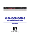
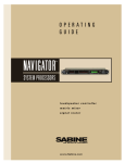
DXP4800 Loudspeaker Management System Owner’s INSTALLATION GUIDE Manual REFERENCE TO EC STATEMENT OF CONFORMITY This document confirms that the range of products of Community Professional Loudspeakers bearing the CE label meet all the requirements in the EMC directive 89/336/EEC laid down by the Member States Council for adjustment of legal requirements, furthermore the products comply with the rules and regulations referring to the electromagnetic compatibility of devices from 30 August 1995. The Community Professional Loudspeakers products bearing the CE label comply with the following harmonized or national standards: DIN EN 55013:08-1991 DIN EN 55020:05-1995 DIN EN 50082-1:03-1993 The authorized declaration and compatibility certification resides with the manufacturer and can be viewed upon request. The responsible manufacturer is the company: Community Light & Sound, Inc. Dba: Community Professional Loudspeakers 333 East 5th Street Chester, PA 19013 USA Tel: 610 876-3400 Fax: 610 874-0190 Community DXP4800 Owner’s Manual Page 2 Table of Contents 1.0 2.0 3.0 4.0 5.0 6.0 Introduction .....................................................................4 Features...........................................................................4 Front Panel Functions ....................................................6 Rear Panel Functions .....................................................7 Powering Up the Device .................................................8 Operating the Device ......................................................8 6.1 Input menus ..............................................................8 6.2 Output Menus............................................................9 6.3 System Menus.........................................................11 7.0 Quick Reference ...........................................................15 8.0 PC Control Software .....................................................16 9.0 Specifications ...............................................................17 10.0 Warranty and Service Information ..............................18 Community DXP4800 Owner’s Manual Page 3 1.0 Introduction Welcome! You’ve joined the group of people that have chosen high quality Community loudspeaker systems, accessories, and components for over 35 years. We’re really gratified you did and we will do our best to make sure you are satisfied with your new DXP4800 digital system controller. In order for you to get the most effective use of this product please take a few minutes to read this manual. We have included a great deal of useful information that will help you to realize the best performance, operation, sound quality, and reliability from your new controller. This manual contains information for the proper set-up and operation of the Community DXP4800 controller. While every attempt has been made to ensure this information is correct and up to date, Community continuously incorporates worthwhile improvements to each product which may include changes and/or modifications not contained in this manual. The DXP4800 is a complete 4 input - 8 output digital loudspeaker management system designed for the touring or fixed sound installation markets. The absolute latest in available technology is utilized with 32-bit (40-bit extended) floating point processors and high performance 24-bit Analog Converters. The high-bit DSP prevents noise and distortion induced by truncation errors of the commonly used 24-bit fixed-point devices. A complete set of parameters include I/O levels, delay, polarity, 6 bands of parametric EQ per channel, multiple crossover selections and full function limiters. Precise frequency control is achieved with its 1 Hz resolution. Inputs and outputs can be routed in multiple configuration to meet any requirements. The DXP4800 can be controlled or configured in real time on the front panel or with the intuitive PC GUI accessed via the RS-232 interface. Software upgrade for CPU and DSP via PC keeps the device current with newly developed algorithms and functions once available. Multiple setup storage and system security complete this professional package. The Community DXP4800 is inherently rugged and is carefully packed in well designed cartons. It is a good idea to carefully inspect the unit after it has been removed from the packaging as sometimes there is hidden damage due to some unfortunate incident during shipment. Please note that once the shipment has left Community (or the dealer), the responsibility for damage is borne by the freight company. This means that if there is damage, you must file a claim with the freight company. Each freight company has its own set of regulations that must be followed and forms that must be filled out. Therefore, the freight company must be contacted as soon as a shipping damage problem is discovered. Save the carton and packing material because many damage claims will be considered invalid if these are thrown away. The Community dealer and the factory will try to help in any way possible. Remember, though, it is up to the party receiving the shipment to file a damage claim. It is always a good idea to keep the carton and packing material in case the unit must be shipped back to your dealer or country distributor. CONTENTS The shipping carton contains the following items: (1) (1) (1) (1) DXP4800 Digital System Controller Owner’s manual Warranty card XLink software Community DXP4800 Owner’s Manual Page 4 2.0 Features 4 Inputs and 8 Outputs with flexible routing 32-bit (40-bit extended) floating point DSP 48/96kHz Sampling Rate Selectable High Performance 24-bit A/D Converters 1 Hz Frequency Resolution 6 Parametric Equalizers for each Input and Output Multiple Crossover types with Full Function Limiters Precise Level, Polarity and Delay CPU and DSP upgrade via PC Individual Channel Buttons with Linking capability 4-Line x 26 Character Backlit LCD Display Full 5-segment LED’s on every Input and Output Storage of up to 30 Program Setups Multiple Levels of Security Locks RS-232 Interface for PC Control and Configuration Options include Digital Audio I/O, RS485 and CobraNet Community DXP4800 Owner’s Manual Page 5 3.0 Front Panel Functions 3 1 4 6 5 2 1. Mute keys - Mute/Unmute input and output channels. When an input channel is muted, a red LED will come on for indication. 2. Gain/Menu keys - Selects the corresponding channel for the LCD menu display and is acknowledged by a green LED. The last modified menu will be displayed on the LCD. Linking multiple channels is accomplished by pressing and holding the first channel key, then pushing the other desired channels. This eases programming for same parameters across multiple channels. Multiple Inputs can be linked together and multiple Outputs can be linked together. Inputs and Outputs are linked separately. 3. Peak Level LED - Indicates the current peak level of the Signal: Signal (-42dB), -12dB, -6dB, -3dB, Over/Limit. The Input Over LED references to the device's maximum headroom. The Output Limit LED references to the threshold of the limiter. 4. LCD - Shows all the necessary information to control the unit. 5. Rotary Thumb Wheel - Changes parameter data values. The wheel has travel velocity sensing which eases large incremental data modifications. For modifying delay and frequency (1 Hz resolution), pressing the Speed key simultaneously will increment/decrement the data value by 100X. 6. Menu Control keys - There are 6 menu keys: <<Menu (Menu Down), Menu>> (Menu Up), <<Cursor (Cursor Down), Cursor>> (Cursor Up), Enter/Sys/Speed and Exit. The function of each key is explained below: <<Menu: Previous menu screen Menu>>: Next menu screen <<Cursor: Previous cursor in the menu screen Cursor>>: Next cursor in the menu screen Enter/Sys/Speed: Enter is used only in the System Menu to proceed with selected actions. Sys enters the System Menu from the main menu. Speed modifies delay and frequency (1 Hz resolution mode) data values by 100X. Exit: Exit to the Main Menu Community DXP4800 Owner’s Manual Page 6 4.0 Rear Panel Functions 1,2,3 1,2,3 4 5 6 1. Main Power - Connects via a standard IEC socket. A compatible power cord is supplied with the unit. The voltage input can be switched between 115VAC or 230VAC. The DXP4800 features a voltage switch to choose between 115VAC or 230VAC. 2. Main Fuse - T0.5A-250V for 115VAC and T0.25A-250V for 230VAC. Slow blow type. 3. Power switch - Controls power On/Off. 4. RS232 - a standard female DB9 socket. A straight through cable is required for PC connection. 5. Option slots - Digital Audio I/O, RS485 and CobraNet cards can be installed and connected via these slots. 6. XLR input and outputs - Separate 3-pin XLR connectors are provided for each audio input and output. The device's output stage employs the balanced impedance topology. All I/O connectors have pin 1 as ground (shield), pin 2 as + and pin 3 as -. Community DXP4800 Owner’s Manual Page 7 5.0 Powering Up the Device After powering up the unit, the following initialization screen is displayed on the LCD: ** COMMUNITY *** ** DXP4800 CONTROLLER *** ------ INITIALIZING ------ The initialization process takes about 8 seconds and during that period the unit boots and displays the DXP4800 firmware version. After the initialization process is finished the DXP4800 displays its main screen: ** COMMUNITY *** ******** DXP4800 ******** PROGRAM:01 XXXXXXXXXXXX The screen shows the current program number and program name assigned to the unit. The program assigned is always the last program the user recalled or stored before powering down the unit. Now the DXP4800 is ready to operate. 6.0 Operating the Device Tips: Channel Linking - If the user presses one of the Input or Output Menu keys, holds it down and presses any other Menu key(s) in the same group (Input or Output group), then the channels are linked together. The green menu LEDs for the linked channels are lit. Any modification of the data for the selected channel will be applied to the linked channels as well. To cancel the linking, just press any other Menu key or the Sys key after releasing the held key. 6.1 Input Menus Each of the DXP4800 input channels has a separate Menu key. There are 3 menus for each input channel. Signal - Signal parameters IN_1:XXXXXX MENU:Signal LEVEL:0.00dB POL :+ DELAY:0 (000.000ms) Community DXP4800 Owner’s Manual Page 8 LEVEL - Gain, -40.00dB to +15.00dB in 0.25dB steps. POL - Polarity, can be normal (+) or inverted (-). DELAY - Delay in 21us steps. Can be displayed in ms, ft or m. The time unit of the delay can be changed in the System menu. The maximum delay permitted is 24,000 steps (500ms). EQ - EQ parameters IN_1:XXXXXX MENU:EQ EQ# :1 BW:0.33oct LEVEL:0.00dB Q=4.36 FREQ :1000Hz TYPE:Param EQ# - Selects one of the 6 available Equalizers. LEVEL - EQ level gain. Ranges from -30.00dB to +15.00dB in 0.25dB steps. FREQ - EQ center frequency. Ranges from 20 to 20,000Hz in either 1Hz steps or 1/36 octave steps. The sampling rate and the frequency steps can be selected in the System Menu. BW - EQ Bandwidth. Ranges from 0.02 to 2.50 octaves in steps of 0.01 octave steps for PEQ. The Q value is automatically shown beneath the octave value. For Lo-Slf or HiShf, it is either 6 or 12dB/Oct. Type - Type of EQ. The types can be parametric (PEQ), Lo-shelf (Lo-shf) and Hi-shelf (Hi-shf). Ch-Name - Channel Name IN_1:XXXXXX NAME:XXXXXX 6.2 MENU:Ch-Name Name - Channel name. It is 6 characters in length. Output Menus Each output channel of the DXP4800 has a separate menu key. There are 6 menus for each output channel. Signal - Signal parameters OUT_1:XXXXXX MENU:Signal LEVEL:0.00dB POL :+ DELAY:0 (000.000ms) Refer to the Input Menus for details Community DXP4800 Owner’s Manual Page 9 EQ - EQ paramters OUT_1:XXXXXX MENU:EQ EQ# :1 BW:0.33oct LEVEL:0.00dB Q=4.36 FREQ :1000Hz TYPE:Param Refer to the Input Menus for details XOver - Crossover parameters OUT_1:XXXXXX FTRL:Off FRQL:1000Hz SLPL:24dB MENU:XOver FTRH:Off FRQL:1000Hz SLPH:24dB FTRL - Filter Type of low frequency crossover point (high pass). Types can be Buttwrth (Butterworth), Link-Ri (Linkritz Riley) or Bessel. FRQL - Filter cut-off Frequency of low frequency crossover point (high pass). Ranges from 20 to 20,000Hz in either 1Hz steps or 1/36 octave steps. The frequency steps can be selected in the System Menu. SLPL - Filter Slope of low frequency crossover point (high pass). Ranges from 6 to 48dB/octave (48kHz) or 6 to 24dB/octave (96kHz) in 6dB/octave steps. If the selected Filter Type is Linkritz Riley, the available slopes are 12 / 24 / 36 / 48 dB/octave (48kHz) or 12 / 24 (96kHz). FTRH - Filter Type of high frequency crossover point (low pass). FRQH - Filter cut-off Frequency of high frequency crossover point (low pass). SLPH - Filter Slope of high frequency crossover point (low pass). Filter configuration Low crossover High crossover point point None FTRL Off FTRH Off Highpass FTRL not Off FTRH Off FRQL Lowpass FTRL Off FTRH not Off FRQH Bandpass FTRL not Off FTRH not Off FRQL FRQH Community DXP4800 Owner’s Manual Page 10 Limit - Output Limter OUT_1:XXXXXX MENU:Limit THRESH :+20.0dBu ATTACK :100ms RELEASE:32x THRESH - Limit Threshold. Ranges from -20 to +20dBu in 0.5dB steps. ATTACK - Attack time. Ranges from 0.3 to 1ms in 0.1ms steps, then ranges from 1 to 100ms in 1ms steps. RELEASE - Release time. Can be set at 2X, 4X, 8X, 16X or 32X the attack time. Source - Input Source OUT_1:XXXXXX MENU:Source 1:On 4:Off 2:Off 3:Off 1,2,3,4 – Input channel source for the current output channel. Can be set to enable the input source (On) or disable it (Off). If more than one input source are enabled, they will be added together as the source for the current output channel. Ch-Name - Channel Name OUT_1:XXXXXX NAME:XXXXXX 6.3 MENU:Ch-Name Refer to the Input Menus for details System Menus The System Menus allow the user to control and change parameters that are related to the system behavior and general operation. It can be accessed by pressing the Sys key in the main menu (when no Input/Output or System Menu is activated). All System Menus require the Enter key to be pressed for the selected action. Recall - Program Recall The DXP4800 has a built in non-volatile memory that can store up to 30 different program setups. A program can be recalled using this menu. Community DXP4800 Owner’s Manual Page 11 SYSTEM-SETUP MENU:Recall PROG:01 NAME:XXXXXXXXXXXX PROG - Program Number to be recalled.. NAME - Program Name of the program. This is read only, the user has no access to them. Store - Program store The DXP4800 has a built in non-volatile memory that can store up to 30 different program setups. A program can be stored using this menu. The old program with the same program number will be replaced. Once the program is stored in the flash memory, it can be recalled at a later time, even after power down. SYSTEM-SETUP MENU:Store PROG:01 NAME:XXXXXXXXXXXX PROG - Program Number for the current data to be stored. NAME - Program Name, allows a maximum length of 12 characters. Config - Device Configuration SYSTEM-SETUP MENU:Config MODE:2-Way MODE - configures the mode of operation. Mode: None Stereo 2-Way Stereo 3-Way Stereo 4-Way Out 1 Any In1 In1 In1 Out 2 Any In1 In1 In1 Out 3 Any In2 In1 In1 Out 4 Any In2 In2 In1 Out 5 Any Any In2 In2 Out 6 Any Any In2 In2 Out 7 Any Any Any In2 Out 8 Any Any Any In2 The unit assigns the Input source for the corresponding outputs when the Mode of Configuration is selected. The crossover point parameters like the filter type, cut-off frequency and slope have to be configured manually in the Xover Menu in each Output menu. *Note: The configuration mode configures the input sources when selected. The user can change the source afterwards if desired. It does not keep the configuration in memory. Community DXP4800 Owner’s Manual Page 12 Copy - Copy channels SYSTEM-SETUP SOURCE:In1 TARGET:In2 MENU:Copy Copy Channels from the source to the target. When the Source and Targets are both Inputs or Outputs, all audio parameters will be copied. When one of the Source or the Target is an input while the other is an output, only the Level, Polarity, Delay and EQ are copied. SOURCE - Channel to be copied from. TARGET - Channel to be copied to. General - General system parameters SYSTEM-SETUP MENU:General FREQ MODE :All Freq DELAY UNIT:01 DEVICE# :1 FREQ MODE - Selects the frequency control mode for EQ and crossover filters. Can be 36 steps/octave or All Frequencies (1 Hz resolution). DELAY UNIT - ms, ft or m. DEVICE# - Assigns the device ID from 1 to 16. This ID is useful when a network of more than 1 unit is present. PC Link - PC Link Enable SYSTEM-SETUP MENU:PC Link PCLINK:On PCLINK: - PC Link Enable. It enables (On) or disables (Off) RS232 communication with the PC software. It is recommended to turn off the link when the unit is not connected to the PC. Sampling - Sampling Rate Selection SYSTEM-SETUP MENU:Sampling SAMPLING RATE:96kHz Community DXP4800 Owner’s Manual Page 13 SAMPLING RATE: - Sampling Rate selection. The unit can operate under 48kHz or 96kHz sampling rate according to this option. The device has to be shut down and turned back on for the hardware effect to take place. For 96kHz operation, crossover slopes can be up to 24dB/Oct only, while 48kHz gives crossover slopes to 48dB/Oct. Security - Security Locks The DXP4800 enables the user to secure the unit and prevent undesired changes in the setup. In order to switch between the security level the user must enter the correct password. SYSTEM-SETUP MENU:Security MENU:In-Signal LOCK:No PASSWORD:XXXX MENU - Selects the menu to be locked/unlocked. The options are: • In-Signal - Input Signal Menu (Level, Polarity, Delay). • In-EQ - Input EQ Menu. • In-Name - Input Channel Name Menu. • Out-Signal - Output Signal Menu (Level, Polarity, Delay). • Out-EQ - Output EQ Menu. • Out-Xover - Output Crossover Menu. • Out-Limit - Output Limit Menu. • Out-Source - Output Source Menu. • Out-Name - Output Channel Name Menu. • System - System Menu. LOCK - Selects to lock (Yes) or unlock (No) the corresponding menu. PASSWORD – The password of the DXP4800 is 4 characters in length. The user can change it via the PC application software. The factory default of a new unit does not require a password. Community DXP4800 Owner’s Manual Page 14 7.0 Quick Reference Level Polarity Delay EQ Number EQ Level EQ Frequency Menu <<Menu>> Signal Signal Signal EQ EQ EQ EQ Bandwidth EQ Crossover Low Crossover Low XOver XOver FTRL FRQL Crossover Low XOver SLPL Crossover High Crossover High XOver XOver FTRH FRQH Crossover High XOver SLPH Parameters Out Limit Thresh Out Attack Time Out Release Time Source Channel Name Limit Limit Limit Source Ch-Name Field <<Cursor>> LEVEL POL DELAY EQ# LEVEL FREQ BW THRESH ATTACK RELEASE 1, 2, 3, 4 NAME Min Max -40 +15 Steps 0.25 +/1 1 0.25 1 Units dB 0 24,000 21us steps 1 6 -30 +15 dB 20 20,000 Hz 0.0 2.50 0.01 Octave 2 Off / Butterworth / Linkwitz-Riley / Bessel 20 20,000 1 Hz 48 (48kHz) 6 6 dB/octave 24 (96kHz) Off / Butterworth / Linkwitz-Riley / Bessel 20 20,000 1 Hz 48 (48kHz) 6 6 dB/octave 24 (96kHz) -20 +20 0.5 dBu 0.3 100 0.1/1 ms 2 / 4 / 8 / 16 / 32X Attack time Off / On 6 characters Community DXP4800 Owner’s Manual Page 15 8.0 PC Control Software The DXP4800 is shipped with a special PC Graphic User Interface (GUI) application - XLink. XLink gives the user an option to control the DXP4800 unit from a remote PC via the RS232 serial communication link. The GUI application makes it much easier to control and monitor the device, allowing the user to get the whole picture on one screen. Programs can be recalled and stored from/to the PC’s hard drive, thus expanding the storage to become virtually limitless. XLink software can also be downloaded from Community’s website at www.loudspeakers.net. Community DXP4800 Owner’s Manual Page 16 9.0 Specifications Inputs and Outputs Audio Control Parameters Input Impedance: Output Impedance: Maximum Level: Type: Gain: Polarity: Delay: >10k Ohms 50 Ohms +20dBu Electronically balanced Audio Performance Frequency Response: Dynamic Range: CMMR: Crosstalk: Distortion: +/- 0.1dB (20 to 20kHz) 115dB typ (unweighted) > 60dB (50 to 10kHz) < -100dB 0.001% (1kHz @18dBu) Digital Audio Performance Processor: Sampling Rate: Analog Converters: Propagation Delay: 32-bit (40-bit extended) 48kHz/96kHz High Performance 24-bit 3ms Front Panel Controls Display: 4 x 26 Character Backlit LCD Level Meters: 5 segment LED Buttons: 12 Mute Controls 12 Gain/Menu Controls 6 Menu Controls Dial Encoder: Embedded Thumb Wheel Connectors Audio: RS-232: Power: 3-pin XLR Female DB-9 Standard IEC Socket -40 to +15dB in 0.25dB steps +/Up to 500ms per I/O Equalizers (6 per I/O) Type: Parametric, Hi-shelf, Lo-shelf Gain: -30 to +15dB in 0.25dB steps Bandwidth: 0.02 to 2.50 octaves (Q=0.5 to 72) Crossover Filters (2 per Output) Filter Types: Butterworth, Bessel, Linkwitz Riley Slopes: 6 to 48dB/oct (48kHz) 6 to 24dB/oct (96kHz) Limiters Threshold: Attack: Release: -20 to +20dBu 0.3 to 100ms 2 to 32X the attack time System Parameters No. of Programs: Program Names: Delay Units: Frequency Modes: Security Locks: PC Link: Copy channels: Channel Names: 30 12 character length ms, ft, m 36 steps/oct, 1Hz resolution Any individual menu Off, On All parameters 6 character length General Power: Dimensions: Weight: 115 / 230 VAC (50 / 60Hz) 19”x1.75”x8” (483x44x203 mm) 10lbs / 4.6kg Note: Specifications subject to change without notice Community DXP4800 Owner’s Manual Page 17 10. Warranty and Service Information The Community DXP4800 Electronic System Controller is warranted in the USA to be free from defects in materials and workmanship for a period of one (1) years, as determined by one of the following two methods, whichever is longer: 1. Starting from the date of retail purchase, as noted on the sales receipt from an authorized Community dealer, OR 2. Starting from the date of manufacture, determined by the serial number, if the sales receipt is not available. This warranty applies to the product; therefore, the remainder of the warranty period will be automatically transferred to any subsequent owner. This warranty applies only to failure of a Community DXP4800 caused by defects in materials and workmanship during the stated warranty period. It does not apply to a unit that has been subjected to abuse, accident, modification, improper handling/installation, or repairs made without factory authorization or by anyone other than authorized Community Field Service Stations. This warranty is void if the serial number has been defaced, altered or removed. Products covered by this warranty will be repaired or replaced at the option of Community, without charge for materials or labor, provided all the terms of this warranty have been met. Obtaining Warranty Service: Warranty service may be obtained from the factory or from an authorized Field Service Station. To obtain factory or field warranty service for products purchased in the United States, return the product for inspection to the address below, freight prepaid, in the original packaging. If the original packaging is not available, call or write Community Warranty Service to obtain proper packaging materials or hand carry the product to the nearest Field Service Station. Call (610) 876-3400 for the nearest authorized Field Service Station. Community Warranty Service 333 East 5th Street Chester, PA 19013-4511 For factory service, please call (610) 876-3400 for a Return Authorization (R/A) number before shipping. If the product is shipped, the following information must be included in the package: 1. Owner’s complete name, daytime phone number, return street address and return authorization number. 2. The serial number of the product being returned and a copy of the retail sales receipt, if possible. 3. A complete description of the problem(s) experienced, including a brief description of how the equipment is being used and with what brand, model and output power of amplifier. Upon Community DXP4800 Owner’s Manual Page 18 receipt, the service center will determine if the problem is covered under warranty. If covered under warranty, the product will be repaired or replaced, at Community’s option, and returned to the owner freight prepaid. If the problem is not covered under warranty, the owner will be notified of the problem with an estimate of the repair costs. Consequential and Incidental Damages: Community shall not be liable for any consequential or incidental damages including, without limitation, injury to persons, property, or loss of use. Some states do not allow the exclusion or limitations of consequential or incidental damages, so the above limitations and exclusions may not apply. This Community warranty is not extended by the length of time which an owner is deprived of the use of the product. Repairs and replacement parts provided under the terms of this warranty shall carry only the remaining portion of the warranty. Community reserves the right to change the design of any product from time to time, without notice and with no obligation to make corresponding changes in products previously sold or manufactured. While this warranty gives specific legal rights, there may also be other rights that vary from state to state. No action to enforce this warranty shall be permitted ninety days after expiration of the warranty period. THIS STATEMENT OF WARRANTY SUPERSEDES ANY PREVIOUS WARRANTY STATEMENTS FOR COMMUNITY ELECTRONIC PRODUCTS. WARRANTY INFORMATION AND SERVICE FOR COUNTRIES OTHER THAN THE USA To obtain specific warranty information and available service locations for countries other than the United States of America, contact the authorized Community Distributor for your specific country or region. Community DXP4800 Owner’s Manual Page 19 333 East 5th Street, Chester, PA 19013-4511 U.S.A. Phone (610) 876-3400 Fax (610) 874-0190 www.loudspeakers.net © 2004 Community Light & Sound, Inc. 040624JL Community DXP4800 Owner’s Manual Page 21