1
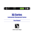
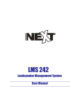
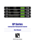
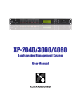
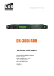
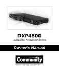
DSLP48 Loudspeaker Management System User Manual Table of Contents 1.0 Introduction ............................................................... 3 2.0 Features ..................................................................... 4 3.0 Front Panel Functions............................................... 5 4.0 Rear Panel Functions................................................ 6 5.0 Powering Up the Device............................................ 7 6.0 Unlocking the Device................................................. 8 7.0 Operating the Device / Input menus......................... 9 7.2 Output Menus.............................................................. 11 7.3 System Menus ............................................................ 13 8.0 Security/Password...................................................... 15 9.0 Quick Reference......................................................... 17 10.0 PC Control................................................................... 18 11.0 Software Navigation.................................................... 21 12.0 Specifications…………………………………………….. 25 13.0 Warranty…………………………………………………… 27 DSLP48 User's manual - Page 2 of 27 1.0 Introduction The DSLP48 is a complete 4 input - 8 output digital loudspeaker management system designed for the touring or fixed sound installation markets. The absolute latest in available technology is utilized with 40 bit floating point processors and high performance 24-bit Analog Converters. The high-bit DSP prevents noise and distortion induced by truncation errors of the commonly used 24-bit fixed-point devices. A complete set of parameters include I/O levels, delay, polarity, 8 bands of parametric EQ per channel, plus 1/3rd oct graphic EQ on the Inputs, multiple crossover selections and full function compressors (Input) and limiters (Output). Precise frequency control is achieved with its 1 Hz resolution. Inputs and outputs can be routed in multiple configurations to meet any requirements. The DSLP48 can be controlled or configured in real time on the front panel or with the intuitive PC GUI accessed via the RS-232/USB or Ethernet interface. Software upgrade for CPU and DSP via PC keeps the device current with newly developed algorithms and functions once available. Multiple setup storage and system security complete this professional package. Shipped contents: - DSLP48 unit - User Manual - DSLP Control Software CD DSLP48 User's manual - Page 3 of 27 2.0 Features > 4 Inputs and 8 Outputs with flexible routing > 40-bit floating point DSP > High Performance 24-bit A/D Converters > 1 Hz Frequency Resolution > 8 Parametric Equalizers for each Input and Output >1/3rd graphic EQ for each input > Multiple Crossover types with Full Function compressors on the inputs >Multiple Crossover types with hard limiting on the outputs > Precise Level, Polarity and Delay on both inputs and outputs > CPU and DSP upgrade via PC > Individual Channel Buttons with Linking capability > 2-Line x 16 Character Backlit LCD Display > Full 5-segment LED on every Input and Output > Storage of up to 30 Program Setups > Security Lock > RS-232-USB-Ethernet Interface for PC Control and Configuration > Future options available DSLP48 User's manual - Page 4 of 27 3.0 Front Panel Functions 1 7 2 3 8 4 5 6 9 1) USB input 2) INPUT Meters Displays the actual Input level 3) Display Screen 4) OUTPUT Meters Displays the onset of limiting-not actual output level 5) Control Bottons <<MENU>> Allows navigation between different menus under a desired page <<CURSER>> Allows navigation between parameters in a particular MENU ENTER Allows data entry to be stored. HOME Brings up the HOME screen 6) DATA WHEEL Allows for data parameters to be changed. 7) RS232 Input jack 8) MUTE and INPUT select buttons (when used in conjunction with the <<MENU button) DSLP48 User's manual - Page 5 of 27 9) MUTE and OUTPUT select buttons (when used in conjunction with the <<MENU button) 4.0 Rear Panel Functions 1 2 3 4 5 6 1) Power switch - Controls power On/Off. 2) Main Fuse - T200mA-250V. Slow blow type. 3) Main Power - Connects via a standard IEC socket. A compatible power cord is supplied with the unit. The voltage input is either 115VAC or 230VAC and is clearly specified on the unit. Voltage requirement has to be stated upon ordering. 4) Ethernet connection. 5) OUTPUT JACKS M XLR 2 Hot- 3 Cold 6) INPUT JACKS F XLR 2 Hot-3 Cold DSLP48 User's manual - Page 6 of 27 5.0 Powering Up the Device After powering up the unit, the following initialization screen is displayed on the LCD: This shows the software version The initialization process takes about 8 seconds and during that period the unit boots and displays the DSLP48 firmware version. After the initialization process is finished the DSLP48 displays its main screen: The screen shows the current program number and program name assigned to the unit. The program assigned is always the last program the user recalled or stored before powering down the unit. Now the DSLP48 is now ready to operate. DSLP48 User's manual - Page 7 of 27 6.0 Unlocking the Device The first thing you will need to do is to make sure your DSLP48 is unlocked. If the unit is locked you can see all functions but cannot make any changes via the front panel nor computer interface. 1: Press the Upper Left MENU key (on the control button on the right side of the unit) and while holding down-press one of the output Mute buttons, Release. This should bring up a screen with a Level control on it. Turn the data wheel and see if this level changes. If it does your DSP is unlocked. If it does not, follow the next steps. 2: If your unit is locked-proceed with the following. On the front of the DSP locate the control buttons towards the right side. Press the HOME button, then the ENTER button. This will get you back to the start screens. Press the Upper Right MENU button repeatedly until you get to the OLD PASSWORD screen. Then press one the same button one more time. This will get you to the SYSTEM PASSWORD screen. Now press ENTER- TWICE. This should unlock your DSP. Try step 1 above to see if the unit is unlocked. You will need to unlock the DSP in this manner whether you are using the computer interface or front panel access. See ALSO the section on Security/Passwords (page 15) for more information. DSLP48 User's manual - Page 8 of 27 7.0 Operating the Device Tips: Channel Linking - If the user presses the LEFT MENU KEYS and the MUTE button of the Input or Output keys, holds it down and press any other MUTE key(s) in the same group (Input or Output group), then the channels are linked together. The green menu LEDs for the linked channels are lit. Any modification of the data for the selected channel will be applied to the linked channels as well. To cancel the linking, just press and hold the LEFT Menu key and a channel. 7.1 Input menus Each of DSLP48 input channels has a separate Menu key. There are 6 menus for each input channel. The MENU buttons select the different blocks of the signal chain. The CURSOR buttons select the different parameters within that particular block. The DATA WHEEL selects the particular adjustment needed. Signal - Signal parameters SIGNAL - Gain, -40.00dB to +15.00dB in 0.25dB steps. POL - Polarity, can be normal (+) or inverted (-). DELAY - Delay in 21us steps. Can be displayed in ms, ft or m. The time unit of the delay can be changed in the System menu. The maximum delay permitted is (90ms). EQ - EQ parameters EQ# - Selects one of the 8 available Equalizers. LEVEL - EQ level gain. Ranges from -30.00dB to +15.00dB in 0.25dB steps. DSLP48 User's manual - Page 9 of 27 (Input Menus continued) FREQ - EQ center frequency. Ranges from 20 to 20,000Hz in either 1Hz steps or 1/36 octave steps. The sampling rate and the frequency steps can be selected in the System Menu. BW - EQ Bandwidth. Ranges from 0.02 to 2.50 octaves in steps of 0.01 octave steps for PEQ. The Q value is automatically shown beneath the octave value. For Lo-Slf or Hi-Shf, it is either 6 or 12dB/Oct. I1: XXXXXX EQ BW: 0.33 Q=4.36 Type - Type of EQ. The types can be parametric (PEQ), Lo-shelf (Lo-shf) and Hi-shelf (Hi-shf), AP (All Pass). GEQ This is a standard 1/3rd octave graphic EQ on ISO centers (you cannot adjust the freq), but only the boost/cut. XOVER This allows for both high and low CUT filters of L/R, Bessel or Butterworth types and 6-48dB/oct slope rates. COMP This is a compressor that allows for THRESHOLD, ATTACK, RELEASE (as a ratio of input time), RATIO, Ch-Name - Channel Name Name - Channel name. It is 6 characters in length. Use the cursor keys and the data wheel to enter the name DSLP48 User's manual - Page 10 of 27 7.2 Output Menus Each output channel of the DSLP48 has a separate menu key. There are 6 menus for each output channel. Signal - Signal parameters Signal Level (Output gain)-Polarity-Delay functions are available just as on the input channels. EQ Refer to the Input Menus for details EQ - EQ parameters XOver - Crossover parameters Refer to the Input Menus for details FRQL - Filter cut-off Frequency of low frequency crossover point (low cut/high pass). Ranges from 20 to 20,000Hz in either 1Hz steps or 1/36 octave steps. The frequency steps can be selected in the System General Menu. SLPL - Filter Slope of low frequency crossover point (low cut/high pass). Ranges from 6 to 48dB/octave. If the selected Filter Type is Linkwitz Riley, the available slopes are 12 / 24 / 36 / 48 dB/octave. FTRH - Filter Type of high frequency crossover point (low pass). FTRH - Filter Type of high frequency crossover point (high cut/low pass). FRQH - Filter cut-off Frequency of high frequency crossover point (high cut/low pass). SLPH - Filter Slope of high frequency crossover point (low pass). DSLP48 User's manual - Page 11 of 27 (Output Menus continued) Filter Configuration None FTRL Highpass Lowpass Bandpass Low crossover point Off FTRL not Off FTRL Off FTRL not Off High crossover point FTRH Off FTRH Off FTRH not Off FTRH not Off FRQL FRQH FRQL FRQH Limit - Output Limiter THRESH - Limit Threshold. Ranges from -20 to +20dBu in 0.5dB steps. The Threshold adjusts the output LEVEL meter to read the onset of limiting-NOT output clipping. ATTACK - Attack time. Ranges from 0.3 to 1ms in 0.1ms steps, then ranges from 1 to 100ms in 1ms steps. RELEASE - Release time. Can be set at 2X, 4X, 8X, 16X or 32X the attack time. Source - Input Source 1,2,3,4 Input channel source for the current output channel. Can be set to enable the input source (On) or disable it (Off). If more than one input source are enabled, they will be added together as the source for the current output channel. The numbers indicate the gain of a particular input routed to that particular output. O1:XXXXXX Source In1:0.00 O1:XXXXXX Source In2:-10 O1:XXXXXX Source In3:Off O1:XXXXXX Source In4:2.5 Ch-Name - Channel Name Refer to the Input Menus for details DSLP48 User's manual - Page 12 of 27 7.3 System Menus The System Menus allow the user to control and change parameters that are related to the system behavior and general operation. It can be accessed by pressing the HOME and then ENTER key in the main menu. All System Menus require the Enter key to be pressed for the selected action. Recall - Program Recall The DSLP48 has a built in non-volatile memory that can store up to 30 different program setups. A program can be recalled using this menu. PROG - Program Number to be recalled. Only first 8 characters of the program name are displayed. Store - Program store The DSLP48 has a built in non-volatile memory that can store up to 30 different program setups. A program can be stored using this menu. The old program with the same program number will be replaced. Once the program is stored in the flash memory, it can be recalled at a later time, even after power down. PROG - Program Number for the current data to be stored. O1:XXXXXX Store PROG:01 NAM - Program Name, allows a maximum length of 12 characters. Use the cursor keys and data wheel for entry O1:XXXXXX Store NAM:XXXXXXXXXXXX Config - Device Configuration MODE - configures the mode of operation. DSLP48 User's manual - Page 13 of 27 (System Menus continued) SYSTEM-SETUP MENU: Config MODE: 2-Way Mode: None Stereo 2-Way Stereo 3-Way Stereo 4-way Out 1 Any In1 In1 In1 Out 2 Any In1 In1 In1 Out 3 Any In2 In1 In1 Out 4 Any In2 In2 In1 Out 5 Any Any In2 In2 Out 6 Any Any In2 In2 Out 7 Any Any Any In2 Out 8 Any Any Any In2 The unit assigns the Input source for the corresponding outputs when the Mode of Configuration is selected. The crossover point parameters like the filter type, cut-off frequency and slope have to be configured manually in the Xover Menu in each Output menu. *Note: The configuration mode configures the input sources when selected. The user can change the source afterwards if desired. It does not keep the configuration in memory. Individual crossover points will have to be adjusted as well. Copy - Copy channels Copy Channels from the source to the target. When the Source and Targets are both Inputs or Outputs, all audio parameters will be copied. When one of the Source or the Target is an input while the other is an output, only the Level, Polarity, Delay and EQ are copied. SOURCE - Channel to be copied from. O1:XXXXXX Copy SOURCE: In1 TARGET - Channel to be copied to. O1:XXXXXX Copy TARGET: In2 DSLP48 User's manual - Page 14 of 27 (System Menus continued) General - General system parameters SYSTEM-SETUP MENU: General FREQ MODE: All Freq DELAY UNIT: 01 DEVICE#: 1 FREQ MODE - Selects the frequency control mode for EQ and crossover filters. Can be 36 steps/octave or All Frequencies (1 Hz resolution). O1:XXXXXX Generl FREQ MODE: All DELAY UNIT - ms, ft or m. O1:XXXXXX Generl DELAY UNIT: ms DSLP48 User's manual - Page 15 of 27 8.0 Security/passwords The DSLP48 enables the user to secure the unit and prevent undesired changes in the setup. In order to lock/unlock the unit the user must enter the correct password. PASSWORD - the password of the DSLP48 is 4 characters in length. The user can change it as needed. SETTING PASSWORD In order to be able to set a new password the front panel needs to be UNLOCKED. (See section on UNLOCKING (page 8) for procedure) Press HOME-ENTER and then the Right MENU button until you get to the SYSTEM OLD PW screen. Press the Right CURSER until it goes past the blanks and then the NEW PW screen will open. Use the Data wheel and the CURSER keys to enter the new Password. Then press ENTER and ENTER again. This will lock out the computer from accessing the DSP. When you try to CONNECT to the DSP it will ask you to LOG ON. Go to the START menu and open the LOG ON box and enter your password. In order to lock out the front panel controls on the DSP unit –On the front panel-press HOME-ENTER and the MENU>> curser until SYSTEM Secure PASSWORD comes up. Enter the same password as NEW PASSWORD. Then ENTER Two times. To CHANGE the PASSWORD go to the software and the SETUP menu and then SECURITY. This will open up a window that you can enter a new password into. This window will not be available if there is not password in the unit. The original password must be set from the NEW PASSWORD entry area. If you want to leave the unit unlocked with no password, then unlock as necessary and go SYSTEM OLD PW and enter the old password, then press ENTER Two times. DSLP48 User's manual - Page 16 of 27 9.0 Quick Reference Parameters < Level Polarity Delay EQ Number EQ Level EQ Frequency EQ Bandwidth Crossover Low Crossover Low Crossover Low Crossover High Crossover High Crossover High Out Limit Thresh Out Attack Time Out Release Time Source Channel Name Menu <<Menu>> Signal Signal Signal EQ EQ EQ EQ XOver XOver XOver XOver XOver XOver Limit Limit Limit Source Ch-Name Field <<Cursor>> LEVEL POL DELAY EQ# LEVEL FREQ BW FTRL FRQL SLPL FTRH FRQH SLPH THRESH ATTACK RELEASE 1, 2, 3,4 NAME Min Max Steps Units > -40 0 1 -30 20 0.0/2 +15 0.25 +/2,400 1 8 1 +15 0.25 20,000 1 3.61 0.01 dB 21us step dB Hz Octave Off / Butterworth / Linkwitz-Riley / Bessel 20 6 20,000 1 48 6 Hz dB/octave Off / Butterworth / Linkwitz-Riley / Bessel 20 20,000 1 Hz 6 48 6 dB/octave -20 +20 0.5 dBu 0.3 100 0.1/1 ms 2 / 4 / 8 / 16 / 32X Attack time Off / On/Level 6 characters DSLP48 User's manual - Page 17 of 27 10.0 PC Control Software The DSLP48 is shipped with a special PC Graphic User Interface (GUI) application – DSLP Control. This gives the user an option to control the DSLP48 unit from a remote PC via the RS232/USB/Ethernet communication link. The GUI application makes it much easier to control and monitor the device, allowing the user to get the whole picture on one screen. Programs can be recalled and stored from/to PC hard drive, thus expanding the storage to become virtually limitless. DSLP48 User's manual - Page 18 of 27 (PC Control Software continued) COMPUTER SETUP 1: Once you have unlocked your DSP you can now connect to it via the computer. Open the software and follow the prompts. If you are able to talk to the device you will get a screen that looks like this: 2: If you have OFF LINE in device 1 Check the following things. Open the SETUP window and go to Port connections. Make sure the ONLINE button is checked under the Details window. If it was not, then check it and close the software and reopen the software and try to connect. 3: If you still do not have a connection, it is probably because you are not using the correct port number. Generally the Serial port is COM 1. If using a USB connection, it could be just about any number. Open the COM Port pull down window under Details in the SETUP-Port Connections window. 4: Scroll down and see if you have ports that have a blank beside the numbers. Most will say “not available”. If you have several with a blank, you will need to go to more detail to see which port is which. But if you only see one port that has a blank name then double-click that number and it should be entered into the port number. You will need to close and restart the software for this change to take effect-instructions on the screen will say this also. 5: If you have several blanks then you will need to identify which port is which. Do the following: Right click on MY COMPUTER-then MANAGE and then DEVICE MANAGER. DSLP48 User's manual - Page 19 of 27 (PC Control Software continued) Scroll down until you see Ports Com and LPT. Open that up. You should see the port number next to the particular device that is using it. In the case of USB it should look like this Note that number and then go back to step 4 above and enter that port number. 6: In a few weird cases you will need to make another change. Following the steps in #5 above, go to the com port being used and double click it. Then open the RESOURCES tab. In the middle there should be a box that says “Use automatic settings”. It does not matter whether the box is checked or not; change it, then hit CHANGE SETTINGS and close out the windows. It may take a couple of seconds for this change to take effect. NOTE: If you have to do step 6 with your computer, you will need to change it every time you start your computer up and use the DSP. You should be able to hook up to the device at this point and go ONLINE. DSLP48 User's manual - Page 20 of 27 11.0 Software Navigation Click on the device you want that is ONLINE and the basic DSP window will open. It is assumed that the user knows their way around the various functions available in modern DSP’s so the particular functions will not be discussed in detail, just basic operation/navigation. METERS The meters in the software indicate the actual level of the signal (unlike the panel display meters that show the onset of limiting on the output). DSLP48 User's manual - Page 21 of 27 (Software Navigation continued) INPUT CHANNELS If you click on the 1st tab on the left (say IN 1). This will open up all the functions available for that particular input. If you want to name the input click on the NAME window until it turns white with a flashing curser. Type in the name you want and hit ENTER. It will turn Red-until you go somewhere else on the screen and then the screen will retain the name you gave it. As a general rule only the data in the DARK BLACK screens can be changed. The data in the lighter black windows is there for reference. Such as with the Delay. The data must be entered in MS, but you will also see the Meter and foot distances also. The same thing applies for the EQ section and bandwidth and Q. Enter the data in Bandwidth and see the Q equivalent. You can change the bandwidth by entering the particular number you want or by dragging the open circles associated with the filter center in the display window. You can change the filter type by clicking on the PEQ window and then use the blue up/down arrows at the bottom of the screen to change to various different types of filters as needed. There are high and low pass filters available. In order to engage or change them, click on the NONE window under the high or low pass filter you want. Then use the blue UP/down arrows at the bottom of the screen to change the filter type. You can also do the same for the slope rate you want. The same thing applies for the output crossover filters as well. DSLP48 User's manual - Page 22 of 27 (Software Navigation continued) OUTPUT Channels The output controls work pretty much the same as the input channels-so be sure to read that first. There are a few exceptions. There is a MIXER on the output side of each DSP channel. There will be a number in it. This number indicates which input channels are routed to it. For example if you have a 1 in the box, then input 1 is routed to that particular output. If you have a 124, that means that input channels 1 and 2 and 4 are routed to that particular output. But these numbers give no indication to the particular level of those inputs. Just that there is some level above infinity attenuation. If you click on the mixer box you will see a mixer field open up with level controls. These are the particular level of the inputs going to that output. There are a couple of “quick” buttons. Just to the left of the fader are 3 small square blue buttons. (One at the top, bottom and about ¾ way up) If you click on those the fader will move to those positions. The ¾ one is the “0” dB position. If you open the entire output channel up (by clicking on the output number) you will see this same mixer available-except in a table form that you can change from that screen if needed. The FILTER window open up the output PEQ and high and low pass filter sections. These operate the same as the Input filters. The output meters (both on the DSP front panel and in the software) may not operate in the way you would normally think. They are referenced to the LIMITER trigger point. So if the limiter threshold is all the way up, then they are for the max output of the device. But as the limiter threshold is turned down, the red “peak” meter is the onset of limiting. Within the limit window is another meter. That shows the amount of actual limiting going on. DSLP48 User's manual - Page 23 of 27 (Software Navigation continued) The output limiter differs from the input compressor in that you cannot adjust the ratio. This is designed solely to keep amplifiers out of clip, while the input compressor can be used for any number of various things as needed-smoothing out a signal-long term level reduction etc. Just adjust the parameters as needed. The DEVICE tab in the bottom left side of the screen allows you to give the device a name-such as the name of the customer and lock out the front panel controls. If you have multiple devises in a system, this is also where you would change the device number. The PRESETS tab in the bottom left side of the screen allows you to same the current setting to the device or to a computer-or both. NOTE: It is important that you save the current settings to the device before turning it off-or they will be lost. The turn on will revert to the last saved settings. Simply click what you want to do, then hit PROCEED. DSLP48 User's manual - Page 24 of 27 12.0 Specifications Inputs and Outputs Input Impedance: Output Impedance: Maximum Level: Type: >10k Ohms 50 Ohms +20dBu Electronically balanced Audio Performance Frequency Response: Dynamic Range: CMMR: Crosstalk: Distortion: +/- 0.1dB (20 to 20kHz) 115dB typ (unweighted) > 100dB (50 to 10kHz) < -100dB 0.002% (1kHz @+4dBu) Digital Audio Performance Processor: 40 bit floating point Sampling Rate: 48kHz Analog Converters: High Performance 24-bit Propagation Delay: 1.5ms Front Panel Controls Display: Level Meters: Buttons: Dial Encoder: 2 x 16 Character Backlit LCD 5 segment LED 12 Mute Controls Embedded Thumb Wheel Connectors Audio: RS-232: USB Ethernet Power: 3-pin XLR Female DB-9 Type B Standard Catt 5 RJ45 Standard IEC Socket DSLP48 User's manual - Page 25 of 27 (Specifications continued) General Power: Dimensions: Weight: 15 / 230 VAC (50 / 60Hz) 19” x1.75” x9” (483x44x203 mm) 10lbs / 4.6kg Audio Control Parameters Gain: -40 to +15dB in 0.25dB steps Polarity: +/Delay: Up to 90ms per input and output (180ms total per path) Equalizers (8 per I/O) Type: Gain: Bandwidth: Parametric, Hi-shelf, Lo-shelf -30 to +15dB in 0.25dB steps 0.02 to 3.61 octaves (Q=0.311 to 72) Crossover Filters (2 per Output) Filter Types: Butterworth, Bessel, Linkwitz Riley, FIR Slopes: 6 to 48dB/oct Limiters Threshold: Attack: Release: Ratio: -20 to +20dBu 0.3 to 100ms 2 to 32X the attack time 1:1-1:40 (compressor only) System Parameters No. of Programs: Program Names: Delay Units: Frequency Modes: Security Lock: Copy channels: Channel Names: 30 12 character length ms, ft, m 36 steps/oct, 1Hz resolution Lock/Unlock All parameters 12 character length Note: Specifications subject to change without notice DSLP48 User's manual - Page 26 of 27 13.0 Warranty The DSLP48 is warranted covering materials and workmanship for a period of one (1) year, as determined by the date of retail purchase (according to the sales receipt from an authorized dealer) or the date of manufacture if the sales receipt is not available (according to the serial number). This warranty applies to the product; therefore, the remainder of the warranty period will be automatically transferred to any subsequent owner. This warranty applies only to failure of a Danley Sound Labs product caused by defects in materials and workmanship during the stated warranty period. It does not apply to a unit that has been subjected to abuse, accident, modification, improper handling/installation, or repairs made without factory authorization or by anyone other than authorized Danley Field Service Stations. This warranty is void if the serial number has been defaced, altered or removed. Products covered by this warranty will be repaired or replaced at the option of Danley, without charge for materials or labor, provided all the terms of this warranty have been met. For factory service, please call or email for a Return Authorization (R/A) number before shipping. If the product is shipped, the following information must be included in the package: 1. Owners complete name, daytime phone number, return street address and return authorization number. 2. The serial number of the product being returned and a copy of the retail sales receipt, if possible. 3. A complete description of the problem(s) experienced, including a brief description of how the equipment is being used and other equipments involved. User Manual v3.0 (FEB 2009) Danley Sound Labs Phone: (770) 535-0204 2196 Hilton Drive, Suite G, Gainesville, Georgia 30501 Fax: (770) 535-8485 www.danleysoundlabs.com DSLP48 User's manual - Page 27 of 27