1
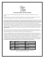
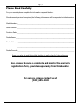
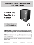
Pool/Spa Heat Pump Installation & Operation Manual Models BR80 XW BR100 BR115 XW BR110 BR135 XW BR135 BR-40101 Version 1.0 HEAT PUMP LIMITED FACTORY WARRANTY This warranty applies to all models installed within the State of Florida after September 1, 2010 (all versions, brands and voltages). Built Right Pool Heaters, LLC warrants this Swimming Pool Heat Pump, to the original owner and installation site, to be free of material or workmanship defects for a limited term. Specific warranty terms, by model, are listed below. The warranty shall begin upon the date of purchase, verified by the owner/operator's proof of purchase documents or, in lieu of owner documents, sixty days from date of manufacture. The warranty form must be submitted by the homeowner within thirty days of purchase or warranty is void. The full warranty term includes parts and on-site labor charges to remove, repair or replace defective components, or failure due to workmanship. Replacement parts shall be warranted for ninety days, or the remainder of the original warranty term: whichever is longer. Manufacturer reserves the right to replace defective parts with new or refurbished parts at its sole discretion. Workmanship or labor to remove, repair or replace defective parts shall be warranted for ninety days or the remainder of the original warranty term: whichever is longer. This warranty does not include transportation charges for equipment or component parts to or from the factory. The owner/operator shall be responsible for any trip or travel charge imposed by the warranty center or servicing agent. As of September 1, 2010, the trip charge for the State of Florida is $50 (fifty) US dollars. Claims for warranty reimbursement must have prior authorization by Built Right, and be performed by a Factory Authorized Service Agent. This warranty is void if the product is repaired or altered in any way by any persons or agencies other than those authorized by Built Right, and is in lieu of all other warranties, expressed or implied, written or oral. The warranty is applicable only if the heat pump has been installed by a licensed professional and operated and maintained expressly and completely in accordance with the purchased model Owner/Installation Manual. These documents are furnished with each heat pump, and additional copies are available by contacting the Built Right office. The liability of Built Right shall not exceed the repair or replacement of defective parts under the referenced limited warranty term, and shall not include consumables (including, but not limited to refrigerant) or transportation to or from the factory. Built Right shall not be liable for any damages of any sort whatsoever, including incidental and consequential damages. This warranty does not include damage due to freezing conditions, negligence or abuse, installations in corrosive environments or atmospheres, nor act of God. There are no implied warranties of merchantability of fitness for a particular purpose that apply to this product. Model BR80 XW BR115 XW BR135 XW BR100 BR110 BR135 On Site Labor (5)Five Years (5)Five Years (5)Five Years (2)Two Years (2)Two Years (2)Two Years Parts (5)Five Years (5)Five Years (5)Five Years (2)Two Years (2)Two Years (2)Two Years ◊ Built Right Pool Heaters, LLC ◊ 8260 Pascal Dr Punta Gorda, FL 33950-4726 ◊ ◊ Phone :941-505-1600, Fax: 941-505-1413 ◊ Page | 1 Table of Contents Important Information Log 2 Introduction 3 Installation Location Recommendations Clearances Equipment Pad Water Piping 4-5 4 4 4 5 Electrical Hook Up Bonding Using an External Controller Wiring Diagram 6-7 6 7 7 Heat Pump Operation / Digital Control Operation Control On/Off Pool/Spa Mode Displaying the Temp. in °F or °C Changing Set Point Temperature Heater Operating Times Initial Startup Defrost Cycle Condensation and Drainage 8-9 8 9 9 9 9 9 9 9 General Maintenance Cleaning Winterizing 10 10 10 Troubleshooting 11 Service Information 12 Page | 2 Please Read Carefully For your records, please complete the information requested below. Should warranty service be required, the following information will be requested to initiate service. Model Number:___________________________________________________________________ Serial Number:____________________________________________________________________ Purchase Date:___________________________________________________________________ Dealer Name:_____________________________________________________________________ Dealer Address:___________________________________________________________________ ____________________________________________________________________ Dealer Phone#:___________________________________________________________________ Keep your sales slip and this booklet together in a safe place for future reference. Also, please be sure to complete and mail in the warranty registration form, provided separately from this booklet. For service, please contact us at (941) 505-1600 Page | 3 INTRODUCTION Thank you for your purchase of a Built Right pool and spa heat pump, proudly made in Punta Gorda, Florida. To ensure a long worry-free life, your heat pump has been manufactured with the highest quality parts available today. A pool heat pump is a cost effective method of heating your pool or spa. Your Built Right heat pump will provide you with years of pool enjoyment. Your new heat pump takes heat from the surrounding air and transfers it into the water. The warmer the air and the more humid the air, the more heat is available for heating your pool. The ideal or rated condition for the heat pump is 80F air temperature, 80% relative humidity, and 80F water temperature. This is true with all air source pool heat pumps. Under ideal conditions, a properly sized heat pump should raise your pool temperature 1 F. per hour. As air temperature and humidity decrease, performance will also decrease. The most efficient time to heat your pool is during daylight hours when outside temperatures are the greatest. Adjustments to your pool pump runtime may be necessary to maintain desired temperature. Like your home air conditioner, it is recommended to set a desired temperature and leave it. A heat pump is best utilized for maintaining a set water temperature. It’s not intended to provide fast heating. When not in use for long periods of time, it is acceptable to shut off your heat pump. When you have a desire to heat your pool, plan accordingly, because it may take the heat pump days to heat your pool back to your desired temperature. The time it takes to heat your pool back up, will depend on your pool temperature and outdoor conditions. Your heat pump will operate when temperatures drop at night, but BTU output will also decrease. When the outdoor temperature drops below 45 F, it is not advisable to operate the pool heat pump. Below 45 F, there is insufficient heat in the air to adequately warm the pool. As with all pool heating methods, you are advised to utilize a pool cover at night and when the pool is not in use. A pool cover is recommended if the night temperature is 15F (8C) less than the desired pool temperature. The cover will help reduce heat loss by limiting evaporation, greatly reducing the overall pool heating costs. The proper use of a cover can reduce operating cost by as much as 50% under certain conditions. Proper installation and use of your heat pump will result in increased performance and reduced heating costs. Your pool heat pump is designed for lower maintenance at a lower cost. But if you want your pool heated efficiently, you must follow the advice we supply in this manual. Page | 4 INSTALLATION Location Recommendations Make sure the heat pump is not located where large amounts of water may enter the heater. This includes roof run-off and sprinklers. Re-direct any suspect sprinkler heads away from the heater. Use a deflector if necessary. (Corrosive sprinkler water damage will void the warranty!) In cases where roof run-off is unavoidable, use of a down spout and/or gutters will protect the heater. Make sure that the digital control does not face directly towards the sun. Damage will not occur, but visibility in direct sunlight may be difficult. Clearances The Built Right pool heat pump is designed for outdoor installation only. Adequate air circulation is necessary for proper heat pump operation. Totally enclosed areas are not recommended. The heat pump should not be installed under a walkway or a porch. At least 4 feet clearance should be allowed above the unit for unrestricted air discharge. All sides of the heat pump require a minimum of 6 inches clearance from all walls or other air flow restrictions. At least 24 inch access must be available for control panel. *These are manufacturer’s tested minimum values given. Where local and national codes apply, and values are different from those specified, use the greater value to ensure safe and proper installation. Equipment Pad Install the heat pump on a flat, slightly pitched surface, preferably a concrete or fabricated slab (pad). This allows proper drainage of condensation and rain water from the base of the unit. If possible, the pad should be placed at the same level or slightly higher than the filter system equipment pad. Slightly pitch the pad so that condensate run-off is directed away from the equipment pad. The base should be completely isolated from the building foundation wall to prevent the possibility of sound or vibration transmission into the building. The heater should be located as close as practical to the existing pool pump and filter to minimize water piping length. Condensation will occur from the evaporator coil while the unit is running and drain at a steady rate, usually 3 to 5 gallons per hour, depending upon ambient air temperature and humidity. The more humid the ambient conditions, the more condensation will be produced. The bottom of the unit acts as a tray to catch rainwater and condensation. Tie Down Straps The unit can be strapped down using the Built Right strap kit*. Attach a strap to each side and anchor to the deck. The Built Right strap kit may be used if local codes require securing the unit to the slab. *The Built Right strap kit is available upon request. Page | 5 Water Piping For your convenience the heater’s inlet and outlet are labeled. 2” PVC Unions are provided with the heater. The piping sequence is as follows: Pool Circulation Pump → Filter → Heater → Chlorinator → Pool To minimize harm to the pool equipment, any inline chlorination device must be located as the last item returning to the pool. Use only rigid PVC piping and all joints should be cleaned then secured with PVC glue. Make sure that the direction of the water flow through the heater is correct as indicated by the labels on the unit. When the piping installation is complete, operate the pool pump and check the system for leaks. When the pool heater is installed below the pool water level, isolation valves must be installed. The pool heater should not be installed more than 6 feet below the pool water surface, or no more than 15 feet above the pool level. Be advised that when pool equipment is located below the pool surface a leak can result in large-scale water loss or flooding. Built Right Pool Heaters, LLC cannot be responsible for such water loss or flooding or the damage caused by either occurrence. The recommended flow rate is 45 gpm through the heater. Flow Rate BR110 BR115 BR135 MIN 20 gpm 20 gpm 30 gpm MAX 70 gpm 70 gpm 70 gpm IMPORTANT! A plumbing bypass is required for installations exceeding 70 gpm. For questions on multiple heater installations, please contact our engineering department. Multiple unit installations should always be in parallel circuits and no closer than 12 inches apart. Page | 6 ELECTRICAL HOOK UP The wiring of your heater should be performed by a qualified electrician in accordance with local code requirements. CAUTION! The main power disconnect must be off before opening the access panel. IMPORTANT! The electrical conduit must be run up through the base of the unit and connected at the control box with a conduit connector. Check the heat pump data label for required breaker size. Copper wire and a properly sized breaker must be used. WARNING! The unit must always be powered off before opening the access panel. BONDING The National Electrical Code and most other codes require that all metallic components of a pool structure, including reinforcing steel, metal fittings, and above ground equipment be bonded together with a solid copper conductor not smaller than 8 AWG. The heat pump, along with pumps and other pool equipment must be connected to this bonding grid. To ensure this requirement is met, a bonding lug is provided on the front bottom right below the control access panel (see drawing below). ALL metal and electrical components of the pool system must be bonded together. On many older pools, the bonding wire may not exist. In this case, a 6 to 8 ft. copper rod must be driven into the ground near the pool equipment and all electrical and metal components must be bonded to the rod. Warranty will be void if system is not properly bonded! Control Box Approved Connector To Main Power Flexible Conduit Attach Bond Wire From Pool Pump Here Page | 7 Using an External Controller Push the remote wires from the external controller through the rubber plug on the bottom left side of the control box. Connect the two remote wires to the two wires from the heater control with the grey wire nuts. For POOL/SPA Remote – Adjust both pool and spa temperature’s to your desired setting. For Remote Thermostat – Adjust pool temperature down to “OFF” and turn spa temperature up to 104° F. For 3 wire remote controls, use 2 wires connected to COM & HIGH at the external controller. Wiring Diagram Legend Comp...Compressor CC...Compressor Capacitor DS....Defrost Temp. Sensor FC...Fan Capacitor FM...Fan Motor HPS...High Pressure Switch WS....Water Temp. Sensor LPS...Low Pressure Switch M1...Main Contactor T1...Transformer FLO...Water Pressure Switch SG...Solar or Gas Relay (Optional) RV...Reversing Valve (Optional) FR...Fan Motor Relay (Optional) JV...Jandy Valve Relay (Optional) High Voltage Field Connection 208-230/1/60 220-240/1/50 Red Wire Use for 208 V Application Black Orange - 230V 240 V L2 L1 M1 T1 12-0-12 Blue T1 T2 Yellow Black Black White FC Brown Green Brown RV SG FM White CC FR Black Digital Control WS DS Yellow AS P/S JV SPR1 SPR2 REVR JAND HPS LPS FLO COMP PUMP Yellow 12-0-12 S Comp R C White Wires Black Red Red Built Right Pool Heater Field Wiring for Wires Remote Switch or T'Stat Blue Wires Optional 24 Vac Field Wiring to Pump Contactor Page | 8 HEAT PUMP OPERATION / DIGITAL CONTROL OPERATION Control On/Off When the unit is powered up, but in the OFF mode, the display will show “OFF” when you press the SET button. To turn the unit on, press the Up arrow button until desired temperature is reached. To turn the unit off press and hold the Down arrow button until the display shows off. This point will be one level below 51 degrees F. This is convenient for shutting the unit down for short periods of time. CAUTION! When the control is in the “OFF” mode, there is still high voltage to the unit. If you want to turn the unit off for long periods of time, shut the main power off to the unit at the main or service disconnect. Page | 9 Pool/Spa Modes The control is equipped with two independent thermostats, one for pool temperature and one for spa temperature. This is to allow the user to preset a temperature of their choice and switch between the two settings. To change between pool and spa modes, Press the SET button until the control reads P_S Press either arrow key to switch from POL to SPA Once the heating mode has been selected, it will be displayed for five seconds and then return to the actual pool water temperature. The lights on the right side of the display indicate the selected mode. ATTENTION! There is a 3 minute time delay upon initiation of a heating cycle. This is to ensure that the critical components do not fail due to short cycling of the heater. Displaying the Temperature in °F or °C The heater comes preset from the factory displaying temperature in °F. To change between °F or °C, Press the SET button until F_C is displayed Press either the UP or DOWN arrow keys until desired display setting is displayed. The control will return to the actual pool water temperature after five seconds in the mode chosen. Changing the Set Point Temperature To change the set point temperature, press the SET button until either POL or SPA is displayed. The programmed temperature will be displayed. Press either the UP or DOWN arrows to change the set point temperature. After adjusting to the desired temperature setting, the display will revert to the actual pool water temperature after five seconds. The default factory setting is “OFF”. Heater Operating Time It is the owner’s responsibility to adequately set the pool pump run time to heat the pool. On colder days, the pool pump run time will need to be extended. The heater requires longer run time in colder weather. The heater is capable of running 24 hours per day if necessary. When you first run your heater, it may need to run continuously for 24 to 48 hours to get the pool up to the desired temperature. On warmer days the heater will not require as long of a run time because there will be less heat loss from the pool. Initial Startup Before starting the heater for the first time, it is important to verify that the dedicated circuit breaker and/or the service disconnect are in the “ON” position. Also make sure that the water is circulating freely through the heater and that the pump is activated. You will then need to set the water temperature to your desired set point. The heater will start after a three minute time delay if the desired set point is higher than the actual pool water temperature. Defrost Cycle The heater is designed to enter the defrost cycle at ambient air temperatures below 48 Fahrenheit. During this cycle, the unit may shut down and the control will display “FS” until the ambient air temperature rises above frosting conditions. Condensation and Drainage Normal heat pump operation will result in water draining from the bottom of the heater. This is due to the evaporator coil condensing water from the humid air. Condensate water will drain out through the drain holes located in the base pan. Your heater typically produces 3 to 5 gallons of water per hour. When the heater is shut off for a period of time, the water created from condensation will evaporate. Page | 10 GENERAL MAINTENANCE CAUTION! Make sure all power is disconnected to the heater prior to washing. Cleaning Your heater requires only minimal maintenance, Make sure the heater has good airflow through the evaporator. To ensure good airflow, remove any leaves, paper or other debris. Also, be sure to keep all shrubs trimmed back from the heater for allowance of sufficient airflow. Make sure the drain holes in the base are free of debris to ensure proper drainage of condensate water. Cleaning of the evaporator coil is only as needed. If the heater’s location is near an ocean or gulf, regularly inspect the coil for salt or sand build up. If build up is excessive, simply rinse the evaporator coil with fresh water. Use of a garden hose with low water pressure will work best. Use extra care, so that you don’t bend the coil fins. The heater’s housing is made from a corrosion-free, UV resistant polymer. It is designed to last for many years. Any dust or debris can be wiped off with a cloth or sprayed off with fresh water. CAUTION! DO NOT USE ALCOHOL-BASED CLEANERS! They could damage the polymer housing. Winterizing In areas where freezing is prevalent, it is necessary to completely drain any standing water from the heater and disconnect it from the pool piping. Draining the water from the heater prevents the internal piping from cracking when exposed to freezing conditions. Cracked piping due to freezing is not covered under the warranty. In areas where freezing conditions are non-existent, winterizing is not required. Page | 11 TROUBLESHOOTING To verify that your heater is heating your pool, place your hand above the unit. Cool air will blow out of the top of the heater, this occurs when the heating indicator is on. The water returning to the pool will be between 3° to 5° warmer* than the overall pool water temperature. There will also be water draining out of the base of the unit after 10 minutes of run time. *depending on model, ambient conditions, and water flow rate. If you believe your heater is not functioning properly, see the troubleshooting guide below. If you are unable to resolve the issue, call our warranty service department at (941)505-1600. CONDITION Control Displays "HP or HP3” POSSIBLE CAUSE Water flow restriction, valve is turned restricting flow. Control Display flashing "dSd" Control Display flashing “PSd” Control Display flashing “FLO” Defrost sensor malfunction or not connected. Water sensor malfunction or not connected. Pool pump is not on, water flow restriction, or incorrect valve position. Control Display is flashing “FS” Or “FS1, FS2, FS3, FS4” Air temperature is too cold for heater operation. Control Displays “FS5” Control Display Flashing "LP” or “LP3” Pool is heating slowly or not getting up to temperature. Water is running out of the bottom of the heater. POSSIBLE SOLUTION Clean pump and filter. Adjust water valves. If problem persists, call factory for service. Call factory for service. Call factory for service. Turn pool pump on. Ensure that skimmer basket, pump strainer basket and pool filter are all clean. Ensure valves are set properly. Wait until air temperature warms up to at least 50 F. Every 15 minutes heater will cycle on for 2 minutes and determine if the temperature is warm enough. Ait temperature too cold after 5 “FS” When air temp rises above 50 F signals. press any key on the control. Built in one hour standby mode if nothing is pressed. If still too cold, 15 min FS cycles will resume. Low refrigerant, or faulty low Call factory for service. pressure sensor. Low or restricted water flow through Clean or replace filter. Inspect and the heater. It is cold outside. Pump clean pool pump. Adjust water timer is not set for a long enough valves. Use a pool cover. Construct a run time. Pool is not being covered. wind break around pool. Set pool High wind speed over pool. Pool pump timer longer. Call factory for area shaded. service. The heater produces up to 3 gallons Shut the heater off for several hours per hour of water condensing from and leave the pool pump running. If the evaporator coil. Internal water the water is still running out, call leak. factory for service. Page | 12 SERVICE INFORMATION All service must be handled by an Authorized Service Center. Warranty may be void if a nonauthorized service representative does service. Do not return the heater to your dealer, as they do not provide service. Before calling for assistance or service, please check the Troubleshooting section of this manual. This may save you the cost of a service call. If you still need help, follow the instructions below. Service can be obtained by calling: (941) 505-1600 When asking for help or service please provide a detailed description of the problem, your heater’s complete model number and serial number, the purchase date and dealer purchased from. This information will help us respond properly to your request. Keep a copy of your sales receipt showing the date of purchase. A valid proof of purchase will assure you of in-warranty service. Notes: ________________________________________________________________________________ ________________________________________________________________________________ ________________________________________________________________________________ ________________________________________________________________________________ ________________________________________________________________________________ ________________________________________________________________________________ ________________________________________________________________________________ ________________________________________________________________________________ ________________________________________________________________________________ ________________________________________________________________________________ ________________________________________________________________________________ ________________________________________________________________________________ NOTES ________________________________________________________________________________ ________________________________________________________________________________ ________________________________________________________________________________ ________________________________________________________________________________ ________________________________________________________________________________ ________________________________________________________________________________ ________________________________________________________________________________ ________________________________________________________________________________ ________________________________________________________________________________ ________________________________________________________________________________ ________________________________________________________________________________ ________________________________________________________________________________ ________________________________________________________________________________ ________________________________________________________________________________ ________________________________________________________________________________ ________________________________________________________________________________ ________________________________________________________________________________ ________________________________________________________________________________ ________________________________________________________________________________ ________________________________________________________________________________ ________________________________________________________________________________ ________________________________________________________________________________ Built Right Pool Heaters, LLC. 8260 Pascal Dr Punta Gorda, Fl 33950-4726