1
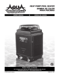
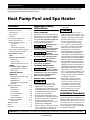
Operating Instructions Please read and save these instructions. Read carefully before attempting to assemble, install, operate or maintain the product described. Protect yourself and others by observing all safety information. Failure to comply with instructions could result in personal injury and/or property damage! Retain instructions for future reference. Heat Pump Pool and Spa Heater Contents Important Safety Instructions. . . . . . . . 1 Installation Procedures. . . . . . . . . . 1 - 2 Unit Inspection. . . . . . . . . . . . . . . . . . 1 Unit Location. . . . . . . . . . . . . . . . . . . 2 Plumbing . . . . . . . . . . . . . . . . . . . . . . 2 Basic Heat Pump Operation. . . . . . 3 - 4 Electrical Connections. . . . . . . . . 2 - 3 Electronic Temp. Controls. . . . . . . . . . 3 - Description. . . . . . . . . . . . . . . . . . . 3 - Buttons. . . . . . . . . . . . . . . . . . . . . . 3 - Water Temp. Set Point . . . . . . . . . 3 Connecting to a Remote System. .. . . 3 High Temperature Lock Out. . . . . . . . 4 SPECIFIC MODEL DETAILS 1100. . . . . . . . . . . . . . . . . . . . . . . . . . 4 Manual Temp. Controls Description. . . . . . . . . . . . . . . . . . . . 4 Indicator Lights . . . . . . . . . . . . . . . . 4 Water Temperature Set Point. . . . . 4 1300h/c . . . . . . . . . . . . . . . . . . . . . . . 4 Electronic Temp. Controls Toggling Between Heat/ Cool . . . . 4 Defrost Cycle . . . . . . . . . . . . . . . . . . 4 1100e TCE, 1300 TCE, 1300h/c TCE. . .. . . . . . . . . . . . . . . 4 - 5 Selecting Functionality of Unit. . . . 4 TCE Operation. . . . . . . . . . . . . . . . . 4 TCO Operation. . . . . . . . . . . . . . 4 - 5 Activating and Setting System Run Time. . . . . . . . . . . . . . . . . . . . . . 5 Application Guidelines. . . . . . . . . 9 - 10 Maintenance . . . . . . . . . . . . . . . . . 9 Condensation. . . . . . . . . . . . . 9 - 10 Pool Blankets. . . . . . . . . . . . . . . . 10 Seasonal Shutdowns. . . . . . . . . . 10 Pool Openings. . . . . . . . . . . . . . . 10 Weather Conditions. . . . . . . . . . . 10 Troubleshooting Guide. . . . . . . . . . . 6 - 7 - Diagnostics. . . . . . . . . . . . . . . . 6 - 7 Wiring Diagrams. . . . . . . . . . . . . . . . . . . 8 Notes. . . . . . . . . . . . . . . . . . . . . . . . . . . . . 9 Warranty . . . . . . . . . . . . . . . . . . . . . . . . 10 Important Safety Instructions READ AND FOLLOW ALL INSTRUCTIONS. Safety Guidelines This manual contains information that is very important to know and understand. This information is provided for SAFETY and to PREVENT EQUIPMENT PROBLEMS. To help recognize this information, observe the following symbols. Warning indicates a potentially hazardous situation which, if not avoided, could result in death or serious injury. Caution indicates a potentially hazardous situation which, if not avoided, may result in minor or moderate injury. Notice indicates important information, that if not followed, may cause damage to equipment. California proposition 65 This product or its power cord may contain chemicals known to the State of California to cause cancer and birth defects or other reproductive harm. Wash hands after handling. General Safety Information • The water in a pool or tub should never exceed 104ºF (40ºC). A water temperature in excess of 104ºF is considered unsafe for all persons. Lower water temperatures are recommended for extended use (exceeding 10 - 15 minutes) and young children. • Excessive water temperatures have a high potential for causing fetal damage during the early months of pregnancy. Pregnant or possibly pregnant women should limit pool or tub water temperatures to 100ºF (38ºC). • Alcohol, drugs, or medication should not be used before or during pool or tub use since their use may lead to unconsciousness with the possibility of drowning. • Obese persons and persons with a medical history of heart disease, low or high blood pressure, circulatory system problems, or diabetes should consult a physician before using a pool or tub. • Persons using medication should consult a physician before using a pool or tub since some medication may induce drowsiness while other medication may affect heart rate, blood pressure, and circulation. • Prolonged immersion in hot water may induce hyperthermia. Hyperthermia occurs when the internal temperature of the body reaches a level several degrees above the normal body temperature of 98.6ºF. The symptoms of hyperthermia include dizziness, fainting, drowsiness, lethargy, and an increase in the internal temperature of the body. The effects of hyperthermia include: unawareness of impending hazard; failure to perceive heat; failure to recognize the need to exit pool or tub; physical inability to exit pool or tub; fetal damage in pregnant women; and unconsciousness resulting in a danger of drowning. • Because the tolerance of water temperature-regulating devices may vary as much as ±5ºF (±3ºC), you should measure the water temperature at several locations using an accurate thermometer before entering a pool or tub. SAVE THESE INSTRUCTIONS. Installation Procedures Unit Inspection Inspect your unit very carefully before installing. Make sure there has been no damage to the evaporator fins or there are no punctures or oil-soaked areas on the box. This would indicate damage to the refrigeration system and should be rejected immediately. REMINDER: Keep your dated proof of purchase for warranty purposes! Attach it to this manual or file it for safekeeping. For parts, product & service information call 877-278-2797. Operating Instructions LIMITED WARRANTY For two (2) years from the date of purchase, Heating Solutions, LLC will repair or replace, at its option, for the original owner any parts of its Heat Pumps (“Product”) which are found upon examination to be defective in materials or workmanship. This Limited Warranty covers labor for a period of two (2) years for Product installed and sold within the state of Florida, for two (2) years for Product installed and sold within the state of Arizona, and for one (1) year for Product sold and installed in all other states of the United States. For five (5) years from the date of purchase, Heating Solutions, LLC will repair or replace, at its option, for the original owner, the compressor (part only), found upon examination to be defective in materials or workmanship. The manufacturer’s Titanium Heat Exchanger carries a lifetime warranty on the titanium tubing part only. Therefore, this warranty for the Titanium heat exchanger will NOT be void due to unbalanced or improper pool chemistry. This warranty for the Titanium heat exchanger will be voided if chemicals are added upstream of the heat pump. Please call 1-877-278-2797 for instructions. Be prepared to provide the model number and serial number when exercising this limited warranty. Purchaser must pay all transportation charges on products or parts submitted for repair or replacement. If a local warranty center requires a service fee for inspection of the model, this charge will be the responsibility of the homeowner. All non-warranty service charges are the responsibility of the original owner. Failure to pay for non-warranty service charges will void this Limited Warranty. This Limited Warranty does not cover Products that have been damaged as a result of accident, abuse, misuse, neglect, improper installation, improper maintenance or failure to operate in accordance with written instructions. All maintenance and service must be performed by service agents approved. Any unauthorized alteration or repairs will void this Limited Warranty. THERE IS NO OTHER EXPRESS WARRANTY. IMPLIED WARRANTIES, INCLUDING THOSE OF MERCHANTABILITY AND FITNESS FOR A PARTICULAR PURPOSE, ARE LIMITED TO ONE (1) YEAR FROM THE DATE OF PURCHASE. THIS IS THE EXCLUSIVE REMEDY AND ANY LIABILITY FOR ANY AND ALL INDIRECT OR CONSEQUENTIAL DAMAGES OR EXPENSES WHATSOEVER IS EXCLUDED. Some states do not allow limitations on how long an implied warranty lasts, or do not allow the exclusions or limitations of incidental or consequential damages, so the above limitations might not apply to you. This limited warranty gives you specific legal rights, and you may also have other legal rights which vary from state to state. In no event, whether as a result of breach of contract warranty, tort (including negligence) or otherwise, shall or its suppliers be liable for any special, consequential, incidental or penal damages including, but not limited to loss of profit or revenues, loss of use of the products or any associated equipment, damage to associated equipment, cost of capital, cost of substitute products, facilities, services or replacement power, downtime costs, or claims of buyer’s customers for such damages. This Limited Warranty does not include freight charges for equipment or component parts, to and from the factory, services such as maintenance or inspection, repair or damage due to negligence such as freezing conditions, incorrect installation, nor acts of God. It also does not include refrigerant or other expendable materials. The liability of shall not exceed the repair or replacement of defective parts under this Limited Warranty. This Limited Warranty also does not include unnecessary service calls due to erroneous operational reports, external valve positions, or electrical service. If a nonwarranty service call is made, and the homeowner is unwilling to pay for the service call, this Limited Warranty will be voided. This Limited Warranty is voided if the product is repaired or altered by any persons or agencies other than those authorized by. This Limited warranty applies only within the continental USA. For warranty outside the continental USA, contact. You MUST retain your purchase receipt along with this form. In the event you need to exercise a warranty claim, you MUST present a copy of the purchase receipt at the time of service. Please call 1-877-278-2797 for service or return authorization and instructions. DO NOT MAIL THIS FORM. Use this form only to maintain your records. MODEL NO.________________________ SERIAL NO.______________________ INSTALLATION DATE _______________________ www.aquaprosystems.com 10 Notes 9 Operating Instructions Installation Procedures (continued) THE UNIT MUST BE TRANSPORTED IN THE UPRIGHT POSITION AT ALL TIMES AND MUST NOT BE DROPPED OR TAILGATED. DAMAGE TO THE UNIT DURING TRANSPORTATION IS NOT THE RESPONSIBILITY OF THE MANUFACTURER. If unit is closer than 18 inches, the manufacturer is not responsible for bad, worn or seized fan motors and capacitors. It is the homeowner’s responsibility to remove any obstructions, at their own cost, before any scheduled maintenance work is performed. If not done, the homeowner is responsible for any additional cost of fees and, if not paid, the the warranty will be void. Unit Location Once the unit has been inspected and cleared of any transportation damage, it is now time to locate the pool heater. It is very important to understand the location of the unit for the best performance of operation. See Figure 1 for location recommendations. If unit is closer than 18 inches, the manufacturer is not responsible for bad, worn or seized fan motors and capacitors. A minimum of 18 inches of clearance between the evaporator coils and shrubs, fences, walls, etc. must be maintained for adequate air intake. A minimum of 5 feet of vertical clearance between the top of the unit and any roof overhang or other obstructions must be maintained in order to prevent the re-circulation of cold air back into the evaporator coils. This is to maintain the efficiency of the unit. A minimum of 36 inches of clearance between the front of the unit (access panel area) and any obstruction must 5 ft. Min. 18 in. Min. 18 in. Min. Figure 1 Unit Location NOTE: This type of constant watering directly on the unit can void your warranty. Condensation drain holes are provided in all units for adequate removal of condensation and rainwater. ALL UNITS WILL HAVE CONDENSATION. THIS SHOULD NOT BE MISTAKEN FOR A LEAK IN THE UNIT. Plumbing Where freezing weather is encountered, the detachable connection/union (provided) must be installed immediately adjacent to the heater to facilitate servicing and Heat pumps are to be installed outside. No Chemical tanks should be located within 5 ft. of the heat pump. UNIONS SHUT-OFF VALVE FILTER BYPASS VALVE CHLORINATOR Figure 2 - Recommended installation layout WARM WATER OUT TO POOL draining of the heat exchanger. Draining is necessary to prevent damage to the condenser shell and coil due to the expansion of freezing water. For proper winterizing, drain all water by blowing any remaining water through the inlet and outlet with low pressure high volume air flow as in using a wet/dry vac in reverse. The minimum water circulation capacity flowing through the pool heater is 25 gallons per minute. The maximum water capacity is 60 gallons per minute on 500 model and 80 gallons per minute on all other models. Intentional setting of the water flow outside of these guidelines will void the warranty. Do not install a water shutoff valve in the piping from the outlet of the pool heater to the pool or tub. However, a check valve that does not include a shut-off feature may be installed for convenience during servicing. A check valve or Hartford Loop is required between the unit and a chlorinator. The chlorinator must be downstream of the heat pump. Failure to do so may void the warranty. If you have an in-floor cleaning system, please take note of any special plumbing requirements to operate all units effectively. Figure 2 shows the recommended installation layout. NOTE: Do not place chlorine tablets, or any other chemicals directly in skimmer basket. Doing this will void the warranty. OUT CHECK VALVE If installing more than one unit, caLL to get all installation specs 36 in. Min. be maintained to allow maintenance on the unit when necessary. The unit must be located on a solid level surface, a minimum of 36 inches x 36 inches for proper drainage. Make sure any sprinkler heads are not directly spraying water on the unit. While heat pumps are made for an outdoor environment, they are not designed to have sprinkler water constantly spraying them. IN 18 in. Min. POOL PUMP COLD WATER IN FROM POOL 2 Electrical Connections All wiring and electrical connections must be performed by a qualified electrician. Installations must be in accordance with local and national codes. Installation Procedures (continued) For 2 wire remotes: 1. Push set button to enter user’s menu. 2. Bring up “POL” setting and arrow temperature down until pool setting reads “off”. 3.Bring up “SPA” setting and arrow temperature up until spa setting reads 104. 4.Set unit to the “POL” mode. 5.Connect remote system with 2 wires to the P/S terminal on control board (see specific model wiring diagram). Overheating, short circuiting and fire damage will result from inadequate wiring. All units are equipped with an electrical wiring schematic inside the electrical panel. If this is missing, please contact the factory at 1-877-278-2797 to obtain one. Units that are equipped with a 208/230 VAC transformer unit must be wired to match the supply power voltage. Refer to the wiring schematic in Figure 5 on page 8 for proper connectivity. Failure to do so could cause overheating, short-circuiting, fire damage and will also void the Warranty. Power L1 and L2 leads are connected to the right side of contactor. These are to be torqued to 40 in./lbs. Failure to torque the L1 and L2 leads may cause overheating or shortcircuiting which could result in fire damage, serious injury or even death. Failure to torque the leads will also void the warranty. Pool Heater is to be installed in accordance with Article 680 of the National Electrical Code (NEC), NFPA 70, and within the requirements of all local codes having jurisdiction. Electronic Temp. Controls (All Units Except 1100) Description • The control located on the front of your heat pump has a large three-character display for the water temperature, set points, and diagnostics (see figure 3 for front panel appearance). The three button keypad includes SET, UP arrow, and DOWN arrow buttons. LED indicators next to the display show if the heat pump is in the pool mode or in the spa mode and if the unit is running. Buttons Press the SET button to change between modes and use the up and down arrows to change the selected mode’s settings. Figure 3 - Front Panel Modes available are: POL - allows you to change the pool water temperature set point SPA - allows you to change the spa water temperature set point P-S - changes between pool and spa settings. LED’s on front panel will indicate current mode selected. F-C - display temperature in Fahrenheit or Celsius TCE Units only: FIL - used to set system run time. H/C Units only: H-C - change between heating and cooling mode. Water Temperature Set Point Temperature set point range is OFF, and 51°F to 95°F for POL mode. For SPA mode, set point range is OFF, and 61°F to 104°F. Pushing the UP arrow or DOWN arrow buttons will prompt the control to display the current set point in the current mode. Continuing to press the UP or DOWN buttons will allow the set point values to scroll until the desired set point is reached. Once the new set point has been reached, stop pressing the UP or DOWN buttons. Once the unit toggles back to the current water temperature display, the set point is entered. The controls have a feature called “Set Point Memory Retention”. If the power is removed from the unit, it retains the last set point displayed. Connecting to a Remote System: All Units Except 1100 This Pool Heater is compatible with all known remote systems in the industry. Please view the wiring diagram on page 8 to see how to connect remote systems to the Electronic Temperature Controller. 3 For 3 wire remotes: 1. Push set button to enter user’s menu. 2.Bring up “POL” setting and use arrows to select desired pool temperature. 3.Bring up “SPA” setting and use the arrows to select the desired spa temperature. 4.Set unit to the “POL” mode. 5.Connect the common and high (or spa) wires to the “P/S” terminals on control board (see specific model diagram). Low or pool wire does not get connected. Note: For heat/ cool units, the remote will not work in the cooling mode. Connecting to Remote Systems: 1100 This Pool Heater is compatible with 2-wire remote systems only, and is not compatible with 3 wire remote systems. Figure 5 on page 8 shows where to connect the remote systems to the Temperature Controller. Connection to AquaLink, Compool, Hayward, AquaLogic or any other 2 wire remote system with their own thermostat: • Remove gray jumper from terminals 1 and 2 on TB1. • Bring the two wires from the remote system to terminals 1 & 2 on Terminal Block 1 (TB1). • The Temperature Control knob must be turned clockwise (highest temp. setting) for the remote system to operate the Pool Heater properly. Operating Instructions Voltage: 208-240/1/60 208/1/60 System Ground Manual check incoming supply voltage. Wire primary transformer connection as illustrated for 208V or 240V. TIME DELAY YELLOW GRAY BLACK (1100 only) BLACK **240V - 24V TRANSFORMER RED BLUE LOW PRESSURE COMPRESSOR *YELLOW YELLOW YELLOW WHITE PRO1100 Only GREEN LIGHT Yellow 1 2 3 4 TB1 GRAY RED RED LIGHT GRAY GRAY CCH RELAY (1100 only) WATER PRESSURE RED BLACK HOT IN OUT PRO1100 Only BLUE RED NO NC S 208 Black BLUE WHITE BLACK NEUT COM R H 240 ter Hea C CAPACITOR THERMOSTAT se (1 Crank ca nly) 0o 10 RED RED (1100 only) C Orange WATER TEMPERATURE SENSOR YELLOW BLUE BLACK *YELLOW L1 (24 VAC) ORANGE L2 CONTACTOR T2 RED (1100 only) RED BLUE F HIGH PRESSURE BLACK RED (1100 only) T1 WHITE BLACK BROWN BROWN/WHITE FAN MOTOR 1100 Series Note: To insure proper operation, GRAY Blue 208 / 240 VAC 50 VA (Primary) 12 / 24 VCT Transformer (Secondary) * COLOR MAY BE YELLOW, BLUE, OR BLACK ** TRANSFORMER CONFIGURATION HAS A 208/240 VAC PRIMARY VOLTAGE OPTION **208/240 Transformer Option Voltage: 208-240/1/60 Figure 5 Digital models Red (H/C Only) Black (H/C Only) Brown Black (H/C Only) Brown & White Black (H/C Only) System Ground FLO AC F1 F2 F3 COM 12 ~ 0 ~ 12 WS DS AS Orange (H/C Only) P/S Black (H/C Only) White Black (Except H/C) LP ** White (H/C Only) HP REVR PUMP SPR2 Note: White fan wire will go to the COM for H/C Only NC NO SPR1 COMP H/C Model Only FAN H/C Model Only REVERSING VALVE Note: To insure proper operation, check incoming supply voltage. Wire primary transformer connection as illustrated for 208V or 240V. Yellow (H/C Only) 208 Red Black Blue Red High pressure switch Closed = OK Opened = high pressure Black Low pressure switch Closed = OK Opened = low pressure * Yellow T2 Yellow Yellow Black Red Red Blue TC Model Only Gray (24 VAC) L4 L3 T3 T4 CONTACTOR To Pool Pump Gray L4 Heater case nk L3 Orange * COLOR MAY BE YELLOW, BLUE, OR BLACK ** WILL READ P/S OR JANDY COM Red Red * Yellow Orange CCH Relay NC NO Remote system 208 / 240 VAC 50 VA (Primary) T1 12 / 24 VCT Transformer (Secondary) Defrost sensor Flow switch Closed = flow Opened = no flow Gray C Voltage: 115 / 208 / 240 VAC / 1 / 60 Input/Output 8 Black R COMPRESSOR Cra Black Wire Is Knotted 240 (24 VAC) L2 L1 Water sensor Blue CONTACTOR Black C CAPACITOR S Black Black H F Figure 6 Troubleshooting Guide (continued) ambient temperature is below 50°F (38°F for all other units with a Digital Control Board), which is too low for the heater to operate, or the unit is low on refrigerant. Once the outside temperature has risen above 60ºF, and the LP code remains, call the factory for repair. PSd: This code means there is a pool sensor defect. Please call to arrange service for the heat pump. DSd: This code means there is a defrost sensor defect. Please call to arrange service for the heat pump. LP3: This is like the “LP” described above, however the unit has shut down because this fault has happened 3 times within a 24 hour time period. If the ambient temperature is below 50°F (38°F for all other units with a digital control board), the problem will most likely persist until the ambient air temperature rises above 50°F. Pressing any of the buttons on the front control panel will restore the unit to its normal operating mode. If the ambient air temperature is not the issue and the heat pump continues to display “LP” or “LP3”, please call to arrange service for the heat pump. HP3: This is like the “HP” described above, however the unit has shut down because this fault has happened 3 times within a 24 hour time period. Please check your pool’s plumbing, valves and pump / filter system for blockages or flow restrictions, as this is most likely the cause for the fault. Pressing any of the buttons on the front control panel will restore the unit to its normal operating mode. If your pump and filter system is working normally and there are no flow restrictions and the heat pump continues to display “HP” or “HP3”, please call to arrange service for the heat pump. Please note, we will not be responsible for non-warranted service calls. FS: This code has the following sequence: •When first displayed, the unit has started the defrost cycle and will reverse operation for 2 minutes. If unit is at acceptable temperature after the defrost cycle, it will go back into heating mode. • If coolant temperature is still too low after the initial 2 minute defrost cycle, unit will shut off the compressor and run only the fan for 60 minutes. If unit is at acceptable temperature after the 60 minutes, it will go back into heating mode. • If coolant has not reached the desired temperature after the 60 minutes, fan only mode, unit will shut down and display “FS”. • Unit will resume normal operation after ambient temperature reaches acceptable operating temperature. MODELS: 1300h/c FS: If in “coolingmode”, this may indicate that there is not enough water flow. COL: This code reminds you that the unit is running in the cooling mode. LP: If in “cooling mode”, this code may indicate that there is not enough water flow HP: If in “cooling mode”, this code may indicate that an external coil is blocked or that there is recirculated air. HOT: This means the pool temperature has increased by 2° while the unit is operating in the “COL” mode. This is only a warning that the unit is having difficulty cooling the pool to the desired temperature. The “HOT” message will remain until either the pool drops to the desired temperature or the set “COL” temperature is raised above the pool’s current temperature. MODELS: 1100e Series, 1300 Series and 1300h/c Series FL3: This code means that water flow was lost. Check the system for flow obstructions. Unit is not running (All Models): •Check the power light. Check to see if the breaker is set. •Make sure the filtration system is on •Make sure the thermostat is higher than the pool water temperature •Make sure the filter is clean and is allowing enough water to flow •Make sure the outside ambient temperature is higher than 50ºF (38°F for all other units with a Digital Control Board) •Make sure the 5-minute time delay has passed •Make sure the 208/230 VAC 7 transformer is wired to match in coming power levels. FOR TCE UNITS •Make sure time setting, in “FIL” mode, is not set to “OFF”. Unit is running but not heating: •Check the air coming out of the top of the unit. It should be approximately 8ºF to 15ºF lower than the surrounding ambient air temperature. If not, call for service. Unit is running but not cooling: •After 5 minutes, Check the air coming out of the top of the unit. It should be approximately 8ºF to 15ºF higher than the surrounding ambient air temperature. If not, call for service Unit will not cool: FOR h/c UNITS: •Make sure P-S is set to “POL” mode as unit will not cool in “SPA” mode. Unit runs continuously: It may be running continuously because it cannot reach the desired temperature. •Lower the temperature setting below the pool water temperature. Unit should turn off. If the unit is still running, call for service. •A pool blanket may be required to help reach this temperature. Also, the filter pump may need to run longer for the heater to reach the desired temperature. FOR TCE UNITS •Make sure the setting is not set to “ON” position in the “FIL” mode. Unit is cycling: •Check the filters for proper water flow •Check the evaporator coil for severe frost •Unit could be low on refrigerant. At this point, call for service and turn off the power to the heater to keep the cycling from damaging the compressor. Operating Instructions Installation Procedures (continued) cycle may reset the time delay, causing the unit to wait an additional five minutes prior to startup. High Temperature Lock Out: All Units Except 1100 Your heat pump includes a special feature to “lock” the high temperature settings. This eliminates the need for a thermostat lock-box. This prevents unauthorized persons from adjusting the heat pump above these desired limits. To activate this feature, please call 877-278-2797 during business hours 8 AM to 5 PM EDT Monday through Friday and we will be glad to assist in setting up this feature. Water Temperature Set Point • Temperature set point range is 45°F to 107°F. Rotating the thermostat knob clockwise will increase the temperature set point, while rotating counterclockwise will decrease the temperature set point. Features All applicable features to these models have been covered in the previous sections. Other models’ features are discussed in designated sections, subsequent to this section. 1100 Manual Temperature Controls Description •The manual Temperature Control is designed to regulate pool and spa water temperature. •There are two indicator lights on the control panel to display the current status of the unit. •The thermostat knob may be adjusted to maintain the desired water temperature. Indicator Lights •There are two indicator lights on the front panel that display unit status. The GREEN light indicates that power to the unit is on. The RED light indicates that the unit is in heating mode. •The RED light may become illuminated prior to heater start up. The RED light will become lit when the thermostat knob is set at or above the water temperature. •The unit has a built in time delay. Every time the unit turns off there is a fiveminute time delay until the unit may be restarted. The HEAT light may turn on during this delay cycle. Do not rotate the thermostat knob during this time delay. Rotating the knob during this •A floating thermometer may be placed in the pool or spa to monitor water temperature. •To initially calibrate the thermostat to the desired set point, turn the thermostat knob fully clockwise. The unit will turn on and begin heating after a possible five minute time delay. Allow the unit to run until pool or spa water reaches the desired temperature. Slowly turn thermostat knob counter-clockwise until the unit turns off. The unit will now maintain this water temperature, providing the circulation pump is running. 1300h/c Electronic Temp. Controls Toggling Between Heating and Cooling Mode The unit will default to the heating mode. If the cooling mode is desired, press the SET button until the H-C screen is displayed. Then press the arrow buttons until “COL” is displayed on the screen. This puts the unit into cooling mode. The water temperature set point will now be the water temperature that the unit is cooling the water to. When the unit is in cooling mode, the screen will flash between the current water temperature and “COL” to remind the user that cooling mode is activated. Defrost Cycle Your h/c unit is capable of keeping your pool warm in very cool temperatures. Most pool heaters will not operate below 50°F. Your h/c unit will work down to 38°F by utilizing a “defrost cycle”. It does this automatically by sensing the coolant temperature and reversing operation 4 for 2 minutes to defrost the evaporator coil and will resume heating function after defrosting the evaporator coil. Selecting Functionality of Unit 1100e Series, 1300 Series and 1300h/c Series This unit is capable of operating as a Time Clock Override (TCO) or as the Time Clock Eliminator (TCE). If you already have a time clock on your swimming pool and would like to maintain its normal operation with the added benefit of a heat pump time clock override – please review the section for the Time Clock Override. If you do not own a time clock for your pool system - please review the section for the Time Clock Eliminator. Time Clock Eliminator (TCE) Operation Please read the functions of this feature carefully. All wiring and electrical connections must be performed by a qualified electrician. Installation must be in accordance with local and national codes. This section allows you to run the heat pump at set intervals during the day. If you have a time clock, and would like to use it please refer to the Time Clock Override section. For the TCE feature to work, your pool pump must be wired to the heat pump See figure 6 on page 8 for wiring the TCE feature • This unit is prepared at the factory with the TCE feature installed, but set to the “off” position in the “FIL” mode. You will need to set the hours of run time for the pump and filter system. See “activating and setting system run time” below. •The function of the TCE is done through a timing sequence of 6 periods per 24 hours. You select the hours for your required filter pump run time, and the heater takes care of the rest. It does this by dividing the system run time equally over the 6 periods, turning the pump 1100e Series, 1300 Series and 1300h/c Series (continued) on for 1/6th of the specified run time and off the remainder of the period unless additional heating is required. The heater will always operate the system on a daily basis for the amount of run time you have selected. The timing sequence begins at the initial start up. •If your pool is at or above the desired operating temperature, the heater will run the system the desired hours each day and spread the time out evenly between the 6 periods. This makes for better filter operation and allows the heater to update the water temperature 6 times per day. •If your pool needs heat, the heater will continue to run the system until the desired temperature is met. If the amount of run time exceeds a period’s run time, the excess time will be subtracted from the next run period(s). Please note that on cold and / or windy days, the unit could run for long times to generate and maintain the desired pool temperature. Please see the “application” section about “pool blankets” to help maintain your pool’s temperature. •The timing function built into the TCE will always run the heat pump for 15 minutes every 4 hours to determine if more heat is needed to maintain the pool’s desired temperature - even if all of the available run time was used in previous cycles. This provides a couple of added benefits. Pools will lose most of their heat at night if left uncovered, however, since the unit is checking for and adding heat when needed, it prevents long recovery times when compared to non-TCE units. The other benefit is that some states and electric utility companies offer a discount for off-peak usage of electricity. Please contact your electricity provider if you have questions. •Example of TCE operation – you require the system to run for 12 hours to meet your pool filtering needs. This means for each of the 6 periods, the heater will run the system for 2 hours and then turn off for 2 hours. If the system needed to run for 3 hours in one of the periods to reach the desired pool temperature, the next period would be 1 hour on and 3 hours off unless additional heating is needed. The cycle continues for 6 periods and renews at the end of each 24 hours. Please call 1-877-278-2797 if you need further clarification of this feature’s operation. Activating and Setting System Run Time - TCE Operation •To set the run time of the system, push the “SET” button repeatedly until “FIL” displays. Then using the “up” and “down” arrows, you can select how many total hours a day you want the system to run for your pump and filtration needs. The range of hours is “off” to 2, 3, 4,… up to 23 hours to “on”. As described before, the run time will then be calculated and spread out over the 6 time periods for 24 hours. Selecting the “on” position will run the pump and filter system continuously. The unit leaves the factory with the “FIL” mode set to “OFF”. Time Clock Override (TCO) Operation All wiring and electrical connections must be performed by a qualified electrician. Installation must be in accordance with local and national codes. This section allows you the option of using an existing time clock with the heat pump. If you do not have a time clock, please refer back to the Time Clock Eliminator section. The pump must be connected to the heat pump and also the time clock for the Time Clock Override feature to work correctly. See figure 4 on page 5 for the optional TCO wiring schematic and electrical connections. •This unit is prepared at the factory with the “FIL” mode set to the “off” position. You will need to set the heat pump’s hours of run time in the “FIL” mode to “2” hours. See “activating and setting system run time” below to set the run time. Leave your time clock set to the desired pump and filter operation time. This will enable the heat pump and filter system to run the desired hours of the day and also provide the benefit of checking if heat is needed every 4 hours. It will do this by running the pump and filter system for 15 minutes. If heat is needed, it will continue to run until the pool has reached the set temperature. If no heat is needed, the system will turn off and continue checking for heat every 4 hours. This provides a couple of added benefits. Pools will lose most of their heat at night if left uncovered, however, since the unit is checking for and adding heat when needed, it prevents long recovery times when compared to non-TCO units. The other benefit is that some states and electric utility companies offer a discount for off-peak usage of electricity. Please contact your electricity provider if you have questions. Activating and Setting System Run Time – TCO Operation INSIDE HEAT PUMP T3 T4 CONTACTOR FOR THE TIME CLOCK OVERRIDE L3 L4 BREAKER JUNCTION BOX TIME CLOCK FILTER PUMP Figure 4 - TCO wiring diagram (optional) 5 •To set the run time of the system, push the “SET” button repeatedly until “FIL” displays. Then using the “up” and “down” arrows, set the hours to “2”. The range of hours is “off” to 2, 3, 4,… up to 23 hours to “on”. By selecting “2” the heat pump will run every 4 hours for 20 minutes, checking if heat is needed. The unit leaves the factory with the “FIL” mode set to “OFF”. Operating Instructions Application Guidelines (All Models) Maintenance All heat pumps are designed for outdoor use. However, some maintenance is required to maintain the full life of the heater and is necessary to maintain your warranty. Annual maintenance should be scheduled to make sure blowing sand or falling debris is removed from the inside of the heater. Rinsing the coil down, monthly, with low water pressure will help keep the base of the unit clear of debris is a must. Do not use a high pressure washer. This can cause damage to your evaporator coils and will void your warranty. It is recommended that a licensed air conditioning specialist perform the annual planned maintenance on your heater. To maintain a valid warranty, a record of annual maintenance must be kept and provided when redeeming the warranty. Annual maintenance includes cleaning the coils, compressors, filters. Clean all rust from the compressor and filter drier then coat it with a layer of paint. The warranty does not cover failure from rust. The unit must be rinsed once a month with CLEAN, LOW-PRESSURE water. The warranty will cover corrosion if you live within 10 miles of a body of Salt Water and only if there is a record showing that the unit was sprayed monthly. If you decide to rinse down the evaporator coils yourself, disconnect all power to the entire equipment pad before you rinse it. This must be done in order to prevent possible electrical shock. Condensation All heat pump pool heaters will have condensation. It is typical to have as much as 6-8 gallons of condensation or water per hour, during a warm, humid day. Do not mistake this for a leak. If you are not sure the water is a leak or is condensation, there are two ways to check this. First, use a pool test strip to see if there is any chlorine or bromine in the water. If there is, contact the factory for service. Second, you can turn off the heater, leave the filter pump running and see if the water stops. If you do not see additional water, then the original water was condensation. Pool Blankets A pool blanket has been proven to greatly reduce the heat loss in the pool and will save as much as 50% - 80% in your heating bills. During the start of the swimming season and the end of the season the heater may not be able to maintain your desired temperature without the use of the pool blanket. Seasonal Shutdowns At the end of your swimming season you may have freezing weather conditions. The unions (provided) must be disconnected to drain any water in the pipes. Clear water by blowing air in the inlet and outlet using a wet/dry vac in reverse. Failure to do so may cause the heat exchanger to expand and crack and will void your warranty. Once water has drained, reconnect the pipes to keep debris out of the system. If you live in an area that does not have freezing weather conditions but are subject to extended periods of non-use, allow the filtration system to continue to run water through the heater. Or you can drain the unit of all water. Pool Openings If at the end of the previous season you disconnected the unions, be sure to connect them before you turn on the filtration system. Once the pool has been cleaned and the unit has been checked for leaks, turn the power on the heater and set the thermostat to the desired temperature. Note: It may take up to three days to reach the desired temperature during the opening of the swimming season. Without a pool blanket, it may take even longer and may not reach the desired temperature until later in the season. Weather Conditions Weather conditions play a big part in the operation of the heater. Low outside ambient temperature, high winds, low relative humidity, and a large amount of shading on the pool will all have an effect on how much time it takes to heat the pool and how 6 much time it might need to maintain the desired temperature. Once the outside ambient temperature drops below 50ºF (38°F for all other units with a digital control board), the heater may not operate. Troubleshooting Guide If the heater is not operating during the initial start-up, check to see if it has been installed properly, per this owner’s manual. Make sure the breaker has been sized properly. The following are conditions to check before calling for a service: Diagnostics Most Models (excluding 1100 & HC units in cooling mode) The display located on the heat pump has diagnostic codes, which help explain any reason for the heater not to be operating properly. The following are the diagnostic codes and the reasons for them appearing: FLO: This code means “Pressure Switch” or water pressure switch. This means there is not enough water pressure to activate the water pressure switch. The cause could be from a clogged filter or a manual by-pass is in the wrong position and is not allowing water into the heater. Once the filter has been cleaned or the by-pass has been changed to allow water to flow through the heater, the FLO display will go away and the water temperature will appear on the display. FL3: This code means that water flow was lost 3 times within 24 hours or unit is programmed wrong. Call 1-877-278-2797 for assistance. Check the system for flow obstructions or contact us at 1-877-2782797 for assistance. HP: This code means “High Pressure” or high pressure switch. Either there is low water flow or high ambient temperature or both. Again, the filter could be clogged and not allowing enough water flow to pass through the heat exchanger and allow the heat to be taken away fast enough, or a by-pass is not in the proper position. Once the filter has been cleaned or the by-pass has been repositioned, the display should return to the temperature of the water. LP: This code means “Low Pressure” or low pressure switch. Either the outside