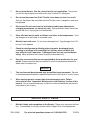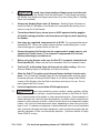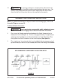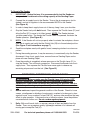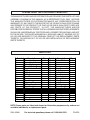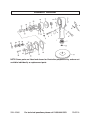
1
®
6” DUAL ACTION
AIR SANDER
Model 42966
ASSEMBLY AND OPERATING INSTRUCTIONS
®
3491 Mission Oaks Blvd., Camarillo, CA 93011
Visit our Web site at http://www.harborfreight.com
TO PREVENT SERIOUS INJURY,
READ AND UNDERSTAND ALL WARNINGS
AND INSTRUCTIONS BEFORE USE.
Copyright© 2004 by Harbor Freight Tools® . All rights reserved. No portion of this manual or
any artwork contained herein may be reproduced in any shape or form without the express
written consent of Harbor Freight Tools.
For technical questions and replacement parts, please call 1-800-444-3353.
PRODUCT SPECIFICATIONS
Item
Description
Orbits Per Minute
10,000
Orbital Motion
5/ "
32
Operating PSI
90 PSI
Diameter
Air Consumption
4.5 CFM @ 90 PSI (No Load)
Pad Thread Size
5/ "
16
Pad and Sanding Paper Diameter
6"
Sanding Paper Type
PSA
x 24
Air Inlet Size
1/4" NPT Female
Additional Features
Dual Action Motion
Variable Speed Throttle Lever
Weight
3.50 Pounds
UNPACKING
When unpacking, check to make sure all the parts shown on the Parts List on page 9 are
included. If any parts are missing or broken, please call Harbor Freight Tools at the number
shown on the cover of this manual as soon as possible.
SAVE THIS MANUAL
You will need this manual for the safety warnings and precautions, assembly, operating,
inspection, maintenance and cleaning procedures, parts list and assembly diagram.
Keep your invoice with this manual. Write the invoice number on the inside of the front
cover. Keep this manual and invoice in a safe and dry place for future reference.
GENERAL SAFETY RULES
WARNING!
READ AND UNDERSTAND ALL INSTRUCTIONS
Failure to follow all instructions listed in the following
pages may result in electric shock, fire, and/or serious injury.
SAVE THESE INSTRUCTIONS
REV 06/04
SKU 42966
For technical questions please call 1-800-444-3353
PAGE 2
WORK AREA
1.
Keep your work area clean and well lit. Cluttered benches and dark areas
invite accidents.
2.
Do not operate pneumatic tools in explosive atmospheres, such as in the
presence of flammable liquids, gases, or dust. Pneumatic tools create sparks
which may ignite flammables.
3.
Keep bystanders, children, and visitors away while operating a pneumatic
tool. Distractions can cause you to lose control. Protect others in the work area
from debris such as chips and sparks. Provide barriers or shields as needed.
PERSONAL SAFETY
1.
Stay alert. Watch what you are doing, and use common sense when
operating a pneumatic tool. Do not use a power tool while tired or under
the influence of drugs, alcohol, or medication. A moment of inattention while
operating pneumatic tools may result in serious personal injury.
2.
Dress properly. Do not wear loose clothing or jewelry. Contain long hair.
Keep your hair, clothing, and gloves away from moving parts. Loose
clothes, jewelry, or long hair can be caught in moving parts.
3.
Avoid accidental starting. Be sure the Throttle Lever is off before
connecting to the air supply. Carrying pneumatic tools with your finger on the
Throttle Lever, or connecting pneumatic tools to the air supply with the Throttle
Lever on, invites accidents.
4.
Remove adjusting keys or wrenches before turning on the tool. A wrench
or a key that is left attached to a rotating part of the tool may result in personal
injury.
5.
Do not overreach. Keep proper footing and balance at all times. Proper
footing and balance enables better control of the tool in unexpected situations.
6.
Use safety equipment. Always wear ANSI approved safety goggles
underneath a full face shield, a dust mask or respirator, and hearing
protection.
TOOL USE AND CARE
1.
Use clamps or other practical ways to secure and support the workpiece to
a stable platform. Holding the work by hand is unstable and may lead to loss of
control. Only work on a workpiece that is properly secured.
SKU 42966
For technical questions please call 1-800-444-3353
PAGE 3
2.
Do not force the tool. Use the correct tool for your application. The correct
tool will do the job better and safer at the rate for which it is designed.
3.
Do not use the power tool if the Throttle Lever does not turn it on or off.
Any tool that cannot be controlled with the Throttle Lever is dangerous and must
be replaced.
4.
Disconnect the air hose from the tool before making any adjustments,
changing accessories, or storing the tool. Such preventive safety measures
reduce the risk of starting the tool accidentally.
5.
Store idle tools out of reach of children and other untrained persons. Tools
are dangerous in the hands of untrained users.
6.
Maintain tools with care. Do not use a damaged tool. Tag damaged tools “Do
not use” until repaired.
7.
Check for misalignment or binding of moving parts, breakage of parts,
cracking or breakage of the sanding Pad, and any other condition that
may affect the tool’s operation. If damaged, have the tool serviced before
using. Many accidents are caused by poorly maintained tools.
8.
Use only accessories that are recommended by the manufacturer for your
model. Accessories that may be suitable for one tool may become hazardous
when used on another tool.
SERVICE
1.
Tool service must be performed only by qualified repair personnel. Service
or maintenance performed by unqualified personnel could result in a risk of injury.
2.
When servicing a tool, use only identical replacement parts. Follow
instructions in the “Inspection, Maintenance, And Cleaning” section of this
manual. Use of unauthorized parts or failure to follow maintenance instructions
may create a risk of injury.
SPECIFIC SAFETY RULES
1.
Maintain labels and nameplates on the Sander. These carry important information. If unreadable or missing, contact Harbor Freight Tools for a replacement.
SKU 42966
For technical questions please call 1-800-444-3353
PAGE 4
2.
CAUTION! To avoid injury, keep hands and fingers away from the rotating Pad (37). Grip the Sander firmly with both hands. If both hands are holding
the Sander, your hands and fingers cannot be cut by the rotating Pad or Sanding
Paper (not Included).
3.
Always use Sanding Paper with a 6” diameter. Sanding Paper that does not
match the Pad (37) diameter of the Sander will run eccentrically causing loss of
control or may fly off the Sander.
4.
To avoid accidental injury, always wear an ANSI approved safety goggles,
full shield, hearing protection, and heavy duty work gloves when operating
the Sander.
5.
Use clean, dry, regulated, compressed air at 90 PSI. Do not exceed the recommended 90 PSI. Never use oxygen, carbon dioxide, combustible gases, or any
other bottled gas as a power source for this tool.
6.
Always disconnect the Sander from its compressed air supply source, and
squeeze the Throttle Lever (11) to release all compressed air in the tool
before performing any maintenance.
7.
Before using the Sander, make sure the Pad (37) is properly attached to the
Drive Spindle (35). Make sure the Pad is balanced, and is not cracked or bent.
8.
The Pad (37) and Sanding Paper will become hot while sanding. Allow the
Pad and Sanding Paper to completely cool before touching.
9.
Allow the Pad (37) to rotate up to full speed before feeding it into the workpiece. Do not force the Sanding Paper into the workpiece when sanding. Apply
moderate pressure, allowing the Sand Paper to cut without being forced. When
turning off the Sander, allow the Pad to spin down and stop on its own. Do not
press against the Pad to stop it.
10.
Industrial applications must follow OSHA requirements.
11.
WARNING! Some dust created by power sanding, sawing, grinding, drilling,
and other construction activities, contain chemicals known (to the State of California) to cause cancer, birth defects or other reproductive harm. Some examples of
these chemicals are: lead from lead-based paints, crystalline silica from bricks and
cement or other masonry products, arsenic and chromium from chemically treated
lumber. Your risk from these exposures varies, depending on how often you do this
type of work. To reduce your exposure to these chemicals: work in a well ventilated
area, and work with approved safety equipment, such as those dust masks that are
specially designed to filter out microscopic particles. (California Health & Safety
Code 25249.5, et seq.)
SKU 42966
For technical questions please call 1-800-444-3353
PAGE 5
12.
WARNING! The warnings, precautions, and instructions discussed in this
manual cannot cover all possible conditions and situations that may occur. The
operator must understand that common sense and caution are factors which
cannot be built into this product, but must be supplied by the operator.
ASSEMBLY AND OPERATING INSTRUCTIONS
NOTE: For additional references to the parts listed in the following pages, refer to the
Assembly Diagram on page 10.
To Attach A Quick Connector:
1.
WARNING! Prior to performing any assembly and/or adjustment procedures, make sure the air supply hose is disconnected from the Sander.
2.
Prior to use, the Sander requires the attachment of a Quick Connector (not included) into its Hose Adapter (2). To do so, wrap approximately 3” of pipe thread
sealer tape (not included) around the male threads of a Quick Connector. Then,
firmly tighten the Quick Connector into the Hose Adapter. (See Figure A.)
3.
Prior to each use, if an automatic oiler is not included in the air compressor hook
up, add two drops of air tool oil (not included) into the Air Inlet fitting of the Sander.
RECOMMENDED COMPRESSED AIR SYSTEM SETUP
ATTACH
QUICK CONNECTOR
TO SANDER
FIGURE A
SKU 42966
For technical questions please call 1-800-444-3353
PAGE 6
To Attach Sanding Paper And The Pad:
1.
Ensure that the Pad is firmly screwed onto the Drive Spindle (35). The Orbital
Hub (28) turns to engage the Drive Spindle (35), allowing the Pad (37) to be
threaded on securely. Turn the Orbital Hub (28) back out of the way before use. If
the Orbital Hub is still in the locked position during use, then the Sander will
not operate properly. (See Figure C.)
2.
The Sander only uses 6” diameter, PSA Stick, (self-sticking) Sanding Paper (not
included). Make sure to attach the Sanding Paper firmly to the Pad (37).
(See Figure B.)
DRIVE SPINDLE (35)
THROTTLE LEVER (11)
PAD (37)
FIGURE B
BOTTOM VIEW
ORBITAL HUB (28)
DRIVE SPINDLE (35)
- UNLOCKED For operation
- LOCKED To tighten or
loosen pad
FIGURE C
REV 05/05
SKU 42966
For technical questions please call 1-800-444-3353
PAGE 7
To Operate The Sander:
1.
IMPORTANT: Before first use, it is recommended to test the Sander on
scrap material to determine the cutting capacity of the Sanding Paper.
2.
Connect the air supply hose to the Sander. Turn on the air compressor (not included), and set its regulator to the recommended 90 PSI for the Sander.
(See Figure A.)
3.
In order to keep the air supply hose out of the way, hang it over your shoulder.
4.
Grip the Sander firmly with both hands. Then squeeze the Throttle Lever (11) and
allow the Pad (37) to move to its fullest speed. NOTE: The Sander features
variable speed action. The harder the Throttle Lever is squeezed, the faster the
Sander operates. (See Figure B.)
5.
NOTE: If the Sander will not turn properly when it contacts the workpiece, disconnect the air supply and verify that the Orbital Hub (28) is in the unlocked position.
(See Figure C and instructions on page 7.)
6.
Sand the workpiece evenly with gentle, broad, sweeping strokes in a crisscross
pattern.
7.
During the sanding process, it may be necessary to occasionally stop the Sander,
disconnect it from its air supply hose, remove the worn Sanding Paper and replace with new Sanding Paper.
8.
Once the sanding is completed, release pressure on the Throttle Lever (11) to
stop the Sander. Turn off the air compressor. Disconnect the Sander from its air
supply hose. Then squeeze the Throttle Lever once again to release any
remaining air pressure from the tool. (See Figure B.)
INSPECTION, MAINTENANCE, AND CLEANING
1.
WARNING! Always make sure the Throttle Lever (11) is in its “OFF”
position, disconnect the Sander from its compressed air supply, and
squeeze the Throttle Lever to release any remaining air pressure from the
tool, before performing any inspection, adjustments, maintenance, or cleaning.
2.
Before each use, inspect the general condition of the Sander. Check for loose
screws, misalignment or binding of moving parts, cracked or broken parts, damaged air hoses, loose, cracked, or bent Pad (37), and any other condition that may
affect its safe operation. If abnormal noise or vibration occurs, have the problem
corrected before further use. Do not use damaged equipment.
3.
Daily: With a soft brush, cloth, or vacuum, remove all dust and debris from the
Sander. Then, use a premium quality, lightweight machine oil to lubricate all
moving parts except the Pad (37).
REV 05/05
SKU 42966
For technical questions please call 1-800-444-3353
PAGE 8
PLEASE READ THE FOLLOWING CAREFULLY
THE MANUFACTURER AND/OR DISTRIBUTOR HAS PROVIDED THE PARTS LIST AND
ASSEMBLY DIAGRAM IN THIS MANUAL AS A REFERENCE TOOL ONLY. NEITHER
THE MANUFACTURER OR DISTRIBUTOR MAKES ANY REPRESENTATION OR
WARRANTY OF ANY KIND TO THE BUYER THAT HE OR SHE IS QUALIFIED TO MAKE
ANY REPAIRS TO THE PRODUCT, OR THAT HE OR SHE IS QUALIFIED TO REPLACE
ANY PARTS OF THE PRODUCT. IN FACT, THE MANUFACTURER AND/OR
DISTRIBUTOR EXPRESSLY STATES THAT ALL REPAIRS AND PARTS REPLACEMENTS
SHOULD BE UNDERTAKEN BY CERTIFIED AND LICENSED TECHNICIANS, AND NOT
BY THE BUYER. THE BUYER ASSUMES ALL RISK AND LIABILITY ARISING OUT OF
HIS OR HER REPAIRS TO THE ORIGINAL PRODUCT OR REPLACEMENT PARTS
THERETO, OR ARISING OUT OF HIS OR HER INSTALLATION OF REPLACEMENT
PARTS THERETO.
PARTS LIST
Part #
1
2
3
4
5
6
7
8
9
10
11
12
13
14
15
16
17
18
19
20
21
Description
Motor Housing
Hose Adapter
Valve Cap
Throttle Valve Spring
Throttle Valve Shaft
O-Ring
O-Ring
O-Ring
Hex Nut
Screw
Throttle Lever
Retaining Ring
O-Ring
Regulator Valve
Retaining Ring
Bearing
End Plate
Cylinder
Pin
Rotor
Rotor Blade
Qty.
1
1
1
1
1
1
1
1
1
1
1
1
1
1
1
2
2
1
1
1
5
Part #
22
23
24
25
26
27
28
29
30
31
32
33
34
35
36
37
38
39
40
41
Description
Rotor Shaft
Key
Gasket
Drive Housing
Cap Screw
Cap Screw
Orbital Hub
Hex Nut
Spindle Lock
Spring Washer
Cap Screw
Hex Screw
Ball Bearing
Drive Spindle
Retaining Ring
Pad
Inlet Screen
O-Ring
Spacer
Spring Washer
Qty.
1
1
1
1
4
1
1
1
1
1
1
1
1
1
1
1
1
1
1
1
NOTE: Some parts are listed and shown for illustration purposes only, and are not
available individually as replacement parts.
SKU 42966
For technical questions please call 1-800-444-3353
PAGE 9
ASSEMBLY DIAGRAM
NOTE: Some parts are listed and shown for illustration purposes only, and are not
available individually as replacement parts.
SKU 42966
For technical questions please call 1-800-444-3353
PAGE 10