1
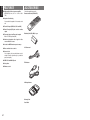
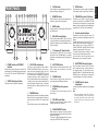
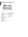
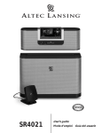
Model SR4021 User Guide
Receiver
IMPORTANT SAFETY
INSTRUCTIONS
CAUTION
RISK OF ELECTRIC SHOCK
DO NOT OPEN
CAUTION: TO REDUCE THE RISK OF ELECTRIC SHOCK,
DO NOT REMOVE COVER (OR BACK)
NO USER-SERVICEABLE PARTS INSIDE
REFER SERVICING TO QUALIFIED SERVICE PERSONNEL
The lightning flash with arrowhead symbol within an equilateral triangle is
intended to alert the user to the presence of uninsulated “dangerous voltage”
within the product’s enclosure that may be of sufficient magnitude to constitute
a risk of electric shock to persons.
READ BEFORE OPERATING EQUIPMENT
This product was designed and manufactured to
meet strict quality and safety standards. There are,
however, some installation and operation precautions
which you should be particularly aware of.
1.
Read Instructions – All the safety and
operating instructions should be read before
the product is operated.
2.
Retain Instructions – The safety and
operating instructions should be retained for
future reference.
3.
Heed Warnings – All warnings on the product
and in the operating instructions should be
adhered to.
4.
Follow Instructions – All operating and use
instructions should be followed.
5.
CAUTION: TO PREVENT ELECTRIC SHOCK, MATCH WIDE BLADE OF PLUG
TO WIDE SLOT, FULLY INSERT.
Cleaning – Unplug this product from the
wall outlet before cleaning. Do not use liquid
cleaners or aerosol cleaners. Use a damp
cloth for cleaning.
6.
ATTENTION: POUR ÉVITER LES CHOCS ÉLECTRIQUES, INTRODUIRE LA
LAME LA PLUS LARGE DE LA FICHE DANS LA BORNE CORRESPONDANTE
DE LA PRISE ET POUSSER JUSQU’AU FOND.
Attachments – Do not use attachments not
recommended by the product manufacturer
as they may cause hazards.
7.
Water and Moisture – Do not use this product
near water-for example, near a bath tub,
wash bowl, kitchen sink, or laundry tub, in a
wet basement, or near a swimming pool, and
the like.
8.
Accessories – Do not place this product on
an unstable cart, stand, tripod, bracket, or
table. The product may fall, causing serious
injury to a child or adult, and serious damage
to the product. Use only with a cart, stand,
tripod, bracket, or table recommended by the
manufacturer, or sold with the product. Any
mounting of the product should follow the
manufacturer’s instructions, and should use
a mounting accessory recommended by the
manufacturer.
The exclamation point within an equilateral triangle is intended to alert the
user to the presence of important operating and maintenance (servicing)
instructions in the literature accompanying the product.
WARNING
TO REDUCE THE RISK OF FIRE OR ELECTRIC SHOCK,
DO NOT EXPOSE THIS APPLIANCE TO RAIN OR MOISTURE.
NOTE TO CATV SYSTEM INSTALLER:
This reminder is provided to call the CATV (Cable-TV) system installer’s attention to Section 820-40 of the
NEC which provides guidelines for proper grounding and, in particular, specifies that the cable ground shall
be connected to the grounding system of the building, as close to the point of cable entry as practical.
NOTE:
This equipment has been tested and found to comply
with the limits for a Class B digital device, pursuant
to Part 15 of the FCC Rules. These limits are
designed to provide reasonable protection against
harmful interference in a residential installation. This
equipment generates, uses and can radiate radio
frequency energy and, if not installed and used in
accordance with the instructions, may cause harmful
interference to radio communications. However,
there is no guarantee that interference will not occur
in a particular installation. If this equipment does
cause harmful interference to radio or television
reception, which can be determined by tuning the
equipment off and on, the user is encouraged to
try to correct the interference by one or more of the
following measures:
- Reorient or relocate the receiving antenna.
- Increase the separation between the equipment
and receiver.
- Connect the equipment into an outlet on a
circuit different from that to which the receiver is
connected.
- Consult the dealer or an experienced radio/TV
technician for help.
NOTE:
Changes or modifications not expressly approved by
the party responsible for compliance could void the
user’s authority to operate the equipment.
9.
A product and cart combination should be
moved with care. Quick stops, excessive
force, and uneven surfaces may cause the
product and cart combination to overturn.
10.
Ventilation – Slots and openings in the
cabinet are provided for ventilation and to
ensure reliable operation of the product and
to protect it from overheating, and these
openings must not be blocked or covered.
The openings should never be blocked by
placing the product on a bed, sofa, rug, or
other similar surface. This product should not
be placed in a built-in installation such as a
bookcase or rack unless proper ventilation is
provided or the manufacturer’s instructions
have been adhered to.
11.
Power Sources – This product should be
operated only from the type of power source
indicated on the marking label. If you are
not sure of the type of power supply to your
home, consult your product dealer or local
power company. For products intended to
operate from battery power, or other sources,
refer to the operating instructions.
12.
Grounding or Polarization – This product
may be equipped with a polarized
alternatingcurrent line plug (a plug having
one blade wider than the other). This plug will
fit into the power outlet only one way. This is
a safety feature. If you are unable to insert
the plug fully into the outlet, try reversing the
plug. If the plug should still fail to fit, contact
your electrician to replace your obsolete
outlet. Do not defeat the safety purpose of
the polarized plug.
16.
Lightning – For added protection for this
product during a lightning storm, or when it is
left unattended and unused for long periods
of time, unplug it from the wall outlet and
disconnect the antenna or cable system. This
will prevent damage to the product due to
lightning and power-line surges.
17.
Power Lines – An outside antenna system
should not be located in the vicinity of
overhead power lines or other electric light or
power circuits, or where it can fall into such
power lines or circuits. When installing an
outside antenna system, extreme care should
be taken to keep from touching such power
lines or circuits as contact with them might be
fatal.
AC POLARIZED PLUG
13.
14.
15.
Power-Cord Protection – Power-supply cords
should be routed so that they are not likely
to be walked on or pinched by items placed
upon or against them, paying particular
attention to cords at plugs, convenience
receptacles, and the point where they exit
from the product.
Protective Attachment Plug – The product
is equipped with an attachment plug having
overload protection. This is a safety feature.
See Instruction Manual for replacement or
resetting of protective device. If replacement
of the plug is required, be sure the service
technician has used a replacement plug
specified by the manufacturer that has the
same overload protection as the original plug.
Outdoor Antenna Grounding – If an outside
antenna or cable system is connected to the
product, be sure the antenna or cable system
is grounded so as to provide some protection
against voltage surges and built-up static
charges. Article 810 of the National Electrical
Code, ANSI/NFPA 70, provides information
with regard to proper grounding of the mast
and supporting structure, grounding of the
lead-in wire to an antenna-discharge unit,
size of grounding conductors, location
of antennadischarge unit, connection to
grounding electrodes, and requirements for
the grounding electrode. See Figure 1.
18.
Overloading – Do not overload wall outlets,
extension cords, or integral convenience
receptacles as this can result in a risk of fire
or electric shock.
19.
Object and Liquid Entry – Never push objects
of any kind into this product through openings
as they may touch dangerous voltage points
or short-out parts that could result in a fire or
electric shock. Never spill liquid of any kind
on the product.
20.
d.
If the product does not operate normally by
following the operating instructions. Adjust
only those controls that are covered by
the operating instructions as an improper
adjustment of other controls may result in
damage and will often require extensive
work by a qualified technician to restore the
product to its normal operation.
e.
If the product has been dropped or damaged
in any way, and
f.
When the product exhibits a distinct change
in performance this indicates a need for
service.
Damage Requiring Service – Unplug this
product from the wall outlet and refer
servicing to qualified service personnel under
the following conditions:
a.
When the power-supply cord or plug is
damaged.
b.
If liquid has been spilled, or objects have
fallen into the product.
c.
If the product has been exposed to rain or
water.
Replacement Parts – When replacement
parts are required, be sure the service
technician has used replacement parts
specified by the manufacturer or have the
same characteristics as the original part.
Unauthorized substitutions may result in fire,
electric shock, or other hazards.
23.
Safety Check – Upon completion of any
service or repairs to this product, ask the
service technician to perform safety checks
to determine that the product is in proper
operating condition.
24.
Wall or Ceiling Mounting – The product
should be mounted to a wall or ceiling only
as recommended by the manufacturer.
25.
Heat – The product should be situated away
from heat sources such as radiators, heat
registers, stoves, or other products (including
amplifiers) that produce heat.
FIGURE 1
EXAMPLE OF ANTENNA GROUNDING AS PER
NATIONAL ELECTRICAL CODE, ANSI/NFPA 70
Servicing – Do not attempt to service this
product yourself as opening or removing
covers may expose you to dangerous voltage
or other hazards. Refer all servicing to
qualified service personnel.
21.
22.
ANTENNA
LEAD IN WIRE
GROUND
CLAMP
ANTENNA
DISCHARGE UNIT
(NEC SECTION 810-20)
ELECTRIC
SERVICE
EQUIPMENT
GROUND CLAMPS
GROUNDING CONDUCTORS
(NEC SECTION 810-21)
POWER SERVICE GROUNDING
ELECTRODE SYSTEM
(NEC ART 250, PART H)
NEC - NATIONAL ELECTRICAL CODE
This Class B digital apparatus complies with Canadian
ICES-003.
Cet appareil numérique de la Classe B est conforme
à la norme NMB-003 du Canada.
FOREWORD ...........................................1
INTRODUCTION ....................................1
PRECAUTIONS ......................................1
FEATURES .............................................2
ACCESSORIES ......................................2
FRONT PANEL ......................................3
FL DISPLAY ........................................................................4
REAR PANEL .........................................5
REMOTE CONTROL OPERATION .......6
FUNCTION AND OPERATION ..........................................6
THE CONTROLLABLE FUNCTION TABLE ......................7
USING THE REMOTE CONTROL UNIT ...........................7
FUNCTION AND OPERATION ..........................................8
CONNECTIONS .....................................8
CONNECTING SPEAKERS...............................................8
CONNECTING AUDIO COMPONENTS............................9
CONNECTING VIDEO COMPONENTS..........................10
CONNECTING THE REMOTE CONTROL JACKS.........10
CONNECTING THE ANTENNA TERMINALS .................11
BASIC OPERATION (PLAY BACK).....12
SELECTING AN INPUT SOURCE ...................................12
ADJUSTING THE MAIN VOLUME ..................................12
ADJUSTING THE TONE (BASS & TREBLE) AND
BALANCE CONTROL ......................................................12
TEMPORARILY TURNING OFF THE SOUND....................12
USING THE SLEEP TIMER .............................................13
LISTENING THROUGH HEADPHONES .......................13
RECORDING A SOURCE ................................................13
BASIC OPERATION (TUNER).............14
LISTENING TO THE TUNER ...........................................14
PRESET MEMORY ..........................................................15
TROUBLESHOOTING .........................17
TECHNICAL SPECIFICATIONS ..........18
DIMENSIONS ......................................18
FOREWORD
PRECAUTIONS
This section must be read before any connection is
made to the mains supply.
CAUTIONS ON INSTALLATION
EQUIPMENT MAINS WORKING SETTING
For heat dispersal, leave at least 8 ins./20 cm of
space between the top, back and sides of this unit
and the wall or other components.
• Do not obstruct the ventilation holes.
Your Marantz product has been prepared to comply
with the household power and safety requirements
that exist in your area.
SR4021 can be powered by 120V AC only.
8 ins. (0.2 m)
or more
COPYRIGHT
Recording and playback of any material may
require consent. For further information refer to the
following:
—
Copyright Act 1956
—
Dramatic and Musical Performers Act 1958
—
Performers Protection Acts 1963 and 1972
—
any subsequent statutory enactments and
orders
ENGLISH
TABLE OF CONTENTS
RECEIVER SR4021
MULTI JOG
8 ins.(0.2 m)
or more
VOLUME
1
SPEAKERS
2
DISPLAY OFF
DOWN
CLEAR
MEMORY
BASS
SLEEP
BAND
TREBLE
F/P
AUTO TUNE
BALANCE
2
MUTE
RECORDER
PHONO
STANDBY
POWER ON/OFF
UP
T-MODE
SPEAKERS
1
DIMMER
CD
TUNER
1
2
AUX
VCR
DSS
DVD
SOURCE
DIRECT
8 ins.(0.2 m)
or more
PHONES
8 ins. (0.2 m)
or more
INTRODUCTION
Thank you for purchasing the Marantz SR4021
Receiver.
This remarkable component has been engineered
to provide you with many years of home theater
enjoyment. Please take a few minutes to read this
manual thoroughly before you connect and operate
the SR4021.
As there are a number of connection and configuration
options, you are encouraged to discuss your own
particular home theater setup with your Marantz A/V
specialist dealer.
1
ENGLISH
FEATURES
ACCESSORIES
■ High quality full discrete power amplifier
Check the supplied accessories.
80W+80W (8 ohms, 20 Hz – 20 kHz, 0.08%
THD)
Remote control unit (RC4021SR)
■ Speaker 1/2 switching
You can switch the speaker 1/2 via remote control
unit.
■ Four A/V inputs (DVD, DSS, VCR and AUX)
■ One A/V output (VCR) and one video monitor
output
■ Four audio inputs and Two audio outputs
Batteries (AAA, R03, UM-4) 2 pcs
Built in PHONO equalizer (MM)
■ Simulcast playback video signal of video
source with audio source
■ 30 station AM/FM random preset memory
■ Bass and treble tone controls
AC Power cord
■ Source direct
You can bypass the tone and balance controls,
routing the audio signal directly to provide the
pure sound quality.
■ PRE OUT and MAIN IN jacks
■ Sleep timer
FM Antenna
■ Dimmer control
AM Loop Antenna
Warranty Card
User Guide
2
1 2 3
4
5
6
7
8 9 10 11 12
13 14
CLEAR button
y
!6
MEMORY button
RECEIVER SR4021
VOLUME
u
SPEAKERS
2
DISPLAY OFF
DOWN
CLEAR
MEMORY
BASS
SLEEP
BAND
TREBLE
F/P
AUTO TUNE
BALANCE
SPEAKERS
1
UP
T-MODE
2
DIMMER
SOURCE
DIRECT
MUTE
RECORDER
PHONO
STANDBY
POWER ON/OFF
CD
TUNER
1
2
AUX
VCR
DSS
DVD
PHONES
i
19 18
POWER switch and STANDBY
indicator
When this switch is pressed once, the unit turns ON
and the display is illuminated. When pressed again,
the unit turns OFF and the STANDBY indicator is
illuminated.
w
SLEEP (Sleep timer) button
This button is used for setting the sleep timer.
17
16
e
15
MULTI JOG control knob
This knob is used in conjunction with the BASS,
TREBLE and BALANCE buttons, and is used to
adjust tone control and balance control. Also, this
knob is used for the TUNING/PRESET search in
the TUNER mode. In the tuning mode, the reception
frequency is tuned up or down. Turning the control
in the clockwise direction tunes the frequency up.
Turning the control in the counterclockwise direction
tunes the reception frequency down. In the preset
mode, the selection of the preset channel is moved
up or down.
r
DIMMER button
When this button is pressed once display is dimmed.
When this button is pressed twice, the display is
turned off and the “DISPLAY OFF” indicator lights
up.
Press this button again to turn on the display again.
BALANCE control button
Press this button and turn MULTI JOG control knob
to vary the output level of the left and right channel. If
this button is pressed in Source Direct Mode, Source
Direct is cancelled.
o
q
BAND button
Press this button to switch between FM and AM in
the TUNER mode.
1
MUTE button
Press this button to mute the output to the speakers.
Press it again to return to the previous volume level.
Press this button to enter the tuner preset memory
numbers or station names. (See page 15)
MULTI JOG
!5
Press this button to cancel the tuner preset station or
preset scan tuning. (See page 15)
F (Frequency)/P (Preset) button
During reception of AM or FM, you can change
the function of the UP/DOWN buttons for scanning
frequencies or selecting preset stations by pressing
this button.
!0
AUTO TUNE button
When this button is pressed and the MULTI JOG
knob is turned, auto scan function of the tuner
frequency starts.
!1
T-MODE button
Press this button to select the auto stereo mode or
mono mode when the FM band is selected.
!2
INFRARED receiving sensor
window
This window receives infrared signals from the
remote control.
!3
VOLUME control knob
Adjusts the overall sound level. Turning the control
clockwise increases the sound level.
!4
ENGLISH
t
FRONT PANEL
SPEAKERS (system 1/2) buttons
These buttons are used to select the speaker
system(s) connected to the SPEAKER SYSTEM
1/2 terminals on the rear panel. The corresponding
indicators of the active speakers light. If headphone are
connected, both 1 and 2 are set off automatically.
!7
Function selector buttons
These buttons are used to select the sources. The
selected source name will be displayed on the front
display.
The video function selector, such as DVD, VCR, DSS
and AUX selects video and audio simultaneously.
Audio function sources such as PHONO, CD,
TUNER ,RECORDER 1 and RECORDER 2 may be
selected in conjunction with a Video source.
This feature (Sound Injection) combines a sound
from one source with a picture from another.
Choose the video source first, and then choose a
different audio source to activate this function.
!8
BASS/TREBLE control buttons
Press these buttons and turn MULTI JOG control
knob to adjust the tone by controlling the level of
two frequency bands. To adjust the bass effect,
press BASS button. To adjust the treble effect, press
TREBLE button. If these buttons are pressed in
Source Direct Mode, Source Direct is cancelled.
!9
PHONES jack for stereo
headphones
Conventional dynamic headphones can be plugged
in here.
Note:
When using headphones, the speaker 1 and/or 2 are
switched automatically to OFF and the sound from
the speakers is muted. The speaker 1 and/or 2 return
to the previous setting as soon as the plug is removed
from the jack.
SOURCE DIRECT button
When this button is pressed, the audio signal will
bypass the balance and tone control circuit to provide
the pure sound quality.
To return not to bypass the balance and tone control
circuit, press SOURCE DIRECT button again.
3
ENGLISH
FL DISPLAY
a
TUNED indicator
e
Frequency/Character display
This indicator illuminates when a station is being
received with sufficient signal strength to provide
acceptable listening quality.
This displays the selected station frequency or the
corresponding words when selecting a program
source.
b
f
STEREO indicator
This indicator illuminates when an FM station is
being tuned in stereo condition.
c
MEMORY indicator
When the MEMORY button is pressed, this indicator
blinks for about 5 seconds.
d
SLEEP indicator
This indicator lights up while the sleep timer function
is in use.
4
Preset number display
Shows the selected preset number.
1
2
3
7
4 5 6
AC IN
ENGLISH
,
REAR PANEL
Connect to supplied an AC power cord, and connect
to an AC power outlet.
SR4021 has to be powered by 120V AC only.
8
.
Speaker terminals
Connect your speaker system(s) to these terminals.
There are two sets of terminals, so you can connect
either 1 and/or 2 speaker systems.
ANTENNA
AC OUTLETS
120V
VIDEO
AM
AUX
IN
DSS
IN
DVD
IN
VCR
IN
OUT
MONITOR
OUT
FLASHER
IN
GND
60Hz
AC IN
UNSWITCHED
1.25A 150W
REMOTE
CONTROL
IN
⁄0
SWITCHED
1.25A 150W
OUT
FM (75
GND
)
SYSTEM 1 : MINIMUM 8 OHMS
SYSTEM 2 : MINIMUM 8 OHMS
R
SYSTEM
2
L
MODEL NO. SR4021
AUDIO
PHONO
IN
IN
OUT
IN
OUT
IN
IN
IN
AUX
DSS
DVD
IN
OUT
IN
L
MAIN IN jacks
Use these jacks to connect an extension pre amplifier
or graphic equalizer.
When a graphic equalizer is to be connected,
connect its output jacks with the MAIN IN jacks on
this unit.
When not used, leave these jacks connected with the
supplied connecting pins.
R
CD
RECORDER 1
(CD-R)
RECORDER 2
(TAPE)
12
z
VCR
PRE
OUT
GND (ground) terminal
Antenna terminals
FM antenna terminal
For connecting the supplied FM antenna or for
connecting an external FM antenna with a coaxial
cable, or for connecting a cable network.
AM antenna and ground terminal
For connecting the supplied AM loop antenna. Use
the terminals marked “AM” and “GND”.
The supplied AM loop antenna will provide good AM
reception in most areas. Position the loop antenna to
the best reception.
c
VIDEO IN/OUT
(AUX, DSS, DVD, VCR)
These are the video inputs and output. There are 4
video inputs and 1 video output. Connect VCR, DVD
players, and other video components to the video
inputs.
The 1 video output can be used to be connected to
video tape recorder for making recording.
v
MONITOR output jack
Connect to the TV’s video input (VIDEO IN) jack.
SYSTEM
1
L
SPEAKER SYSTEMS
11 10
Connect the grounding wire from the analog turntable
to this terminal.
x
R
MAIN
IN
b
9
REMOTE CONTROL IN/OUT
terminals
Connect to a Marantz component equipped with
remote control (RC-5) terminals.
n
FLASHER IN (Flasher input
terminal)
This terminal is to control the unit from another
zone.
Connect the control signal from a Keypad, etc.
m
AC OUTLET
Connect the AC power cord of component such as a
DVD or CD player to this outlet.
The marked SWITCHED provides power only when
the SR4021 is turned on and is useful for components
which you use every time you play your system.
⁄1
PRE OUT jacks
Use these jacks to connect an extension power
amplifier or graphic equalizer.
When a graphic equalizer is to be connected,
connect its input jacks with the PRE OUT jacks on
this unit.
When not used, leave these jacks connected with the
supplied connecting pins.
⁄2
AUDIO IN/OUT
(PHONO, CD, RECORDER 1,
RECORDER 2)
These are the analog audio inputs and outputs. There
are 8 audio inputs (4 of which are linked to video
inputs) and 3 audio outputs (1 of which is linked to
video output). The audio jacks are nominally labeled
for recorder1 (CD recorder) recorder2 (cassette tape
deck), compact disc players, DVD players and etc....
The audio inputs and outputs require RCA-type
connectors.
Caution:
• In order to avoid potential turn-off thumps, anything
plugged into these outlets should be powered up
before the SR4021 is turned on.
• The capacity of this AC outlet is 150W. Do not
connect devices that consume electricity more than
the capacity of this AC outlet. If the total power
consumption of the connected devices exceeds the
capacity, the protection circuit shuts down the power
supply.
5
ENGLISH
FUNCTION AND OPERATION
REMOTE CONTROL
OPERATION
The provided remote control unit can be used to
control a Marantz audio/visual component such as a
DVD player, CD player.
The POWER button, numeric buttons and control
buttons are used in common across different input
source components.
The input source controlled with the remote control
unit changes when one of the input selector buttons
on the remote control unit is pressed.
1
2
3
25
24
5
6
7
21
23
22
19
18
12
13
14
15
⁄1
PLAY button
⁄9
CHANNEL/SKIP buttons
• Example
To select the DVD as the input source and play
the DVD player.
Press the DVD button. The input selector of the
SR4021 is switched to DVD and the remote control
unit is set for control of the DVD player.
⁄2
¤0
Press the PLAY button on the remote control
unit.
⁄3
z
MAIN POWER button
Press to switch the power of the SR4021 ON or
STANDBY.
x
Transmitting indicator
Lights up during a button is pressed and an infrared
signal is sending.
c
SOURCE POWER button
DIMMER button
When this button is pressed once, the display
is dimmed. When this button is pressed twice,
the display is turned off and the “DISPLAY OFF”
indicator lights up.
Press this button again to turn on the display again.
b
S (Source)-DIRECT button
BAND / STOP button
(When tuner mode is selected)
Press this button to switch between FM and AM.
(When CD/RECORDER/VCR/DVD mode is selected)
Press this button to stop each programs.
Cursor, ENTER, MENU, etc.
buttons
These buttons are used when operating the DVD
player, VCR, etc. The function of these buttons are
dependent on the function button selected. For the
controllable functions of each input function, please
refer to controllable table on page 7.
⁄4
F.DIR / ANGLE button
(When tuner mode is selected)
Press this button to change tuner mode to Frequency
Direct Call mode. You can call your desired frequency
with numeric button of the remote control unit in this
mode.
⁄5
MEMO / PROG. button
Memory enable button for various preset functions.
⁄6
CLEAR button
This button is used to cancel for certain memory or
programming operations.
⁄7
Numeric buttons 0 to +10
T-MODE button
(When tuner mode is selected)
Press this button to select the auto stereo mode or
mono mode when the FM band is selected.
¤1
P.SCAN button
(When tuner mode is selected)
This button is used to start preset scan when TUNER
mode is selected in SR4021.
¤2
TV INPUT button
Press this button to select TV input mode.
¤3
SPKR 1/2 button
Press this button to select the speaker system (or
systems) which is to be used. Each time it is pressed,
the setting is selected in the following sequence in
turn: 1 only ON → 2 only ON → 1 and 2 ON → 1
and 2 OFF → 1 only ON, and so on. The speaker
indicator (or indicators) corresponding to the speaker
(or speakers) which has been set to the active status
lights.
When headphones have been connected, speakers
1 and 2 are automatically set to OFF.
¤4
Input selector buttons/ FUNCTION
SELECTOR buttons
(AUDIO/VIDEO INPUT)
Press to adjust the volume control of SR4021.
These buttons are used to select a Audio or Video
source component. When one of these buttons
is pressed, the input function of the SR4021 is
changed.
Audio function sources such as PHONO, CD,
TUNER, RECORDER1 and RECORDER2 may be
selected in conjunction with a Video source.
This feature (Sound Injection) combines a sound
from one source with a picture from another.
Choose the video source first, and then choose a
different audio source to activate this function.
,
¤5
When this button is pressed, the audio signal will
bypass the balance and tone control circuit to provide
the pure sound quality.
n
MUTE button
Press this button decrease the sound temporarily.
Press this button again to return to the previous
sound level.
m
VOLUME up (3)/down (4) buttons
BASS up (3)/down (4) buttons
These buttons are used to adjust the tone control of
low frequency sound.
6
PAUSE button
(When CD/RECORDER/VCR/DVD mode is selected)
Press this button to pause each programs.
TUNE/SEARCH buttons
(When tuner mode is selected)
These button are used to increase or decrease the
frequency to which the tuner is currently tuned. Press
and hold one of these buttons to initiate the auto
tuning operation.
(When tuner mode is selected)
These button are used to move up or down through
the preset stations.
v
16
⁄0
⁄8
(When CD/RECORDER/VCR/DVD mode is selected)
Press this button to playback each programs.
Press to switch the power of the source component
after pressing the function selector button.
17
TREBLE up (3)/down (4) buttons
These buttons are used to adjust the tone control of
high frequency sound.
8
9
10
11
20
4
.
These buttons are used to enter figures in the
selection of a tuner preset station and station name
preset or to set select a DVD chapter or title and a CD
track number, etc. The functions of these buttons are
dependent on the function button selected.
SLEEP button
This button is used for setting the sleep timer.
CD
RECORDER 1 RECORDER 2
VCR
(CDR)
(TAPE)
SOURCE POWER
POWER ON/ POWER ON/ POWER ON/ POWER ON/
STANDBY
STANDBY
STANDBY
STANDBY
CHANNEL/SKIP S
PREV
PREV
PREV
CHCHANNEL/SKIP T
NEXT
NEXT
NEXT
CH+
T-DISP. ;
PAUSE
PAUSE
PAUSE
PAUSE
PTY 2
PLAY
PLAY
PLAY
PLAY
TUNE/SEARCH Q
FR
FR
FR
FR
TUNE/SEARCH R
FF
FF
FF
FF
REC 0
REC
REC
REC
BAND 9
STOP
STOP
STOP
STOP
Cursor
Cursor
ENTER
OK
SETUP
INFO
MENU
0-9
+10
AUDIO
SUBTITLE
F.DIR/ANGLE
CLEAR
MEMO/PROG.
SWITCH
DISPLAY
INPUT
NUMERIC
INPUT
CLEAR
CALL
PROGRAM
PREPARING THE REMOTE CONTROL UNIT
USING THE REMOTE CONTROL UNIT
SWITCH
DISPLAY
INPUT
NUMERIC
INPUT
CLEAR
CALL
PROGRAM
SWITCH
DISPLAY
INPUT
NUMERIC
INPUT
CLEAR
CALL
PROGRAM
DISPLAY
CALL UP
MENU
INPUT
NUMERIC
AUDIO
INPUT
CLEAR
-
DSS
DVD
POWER ON/
STANDBY
CHCH+
Cursor
OK
-
POWER ON/
STANDBY
PREV
NEXT
PAUSE
PLAY
FR
FF
STOP
Cursor
OK
SETUP
MENU
DISPLAY
CALL UP
MENU
INPUT
NUMERIC
Input +10
AUDIO
SUBTITLE
ANGLE
INPUT
CLEAR
CALL
PROGRAM
DISPLAY
CALL UP
MENU
INPUT
NUMERIC
AUDIO
INPUT
CLEAR
-
REMOTE CONTROL OPERATIONAL RANGE
The distance between the transmitter of the remote
control unit and the IR SENSOR of the SR4021
should be less than about 5 meters.
If the transmitter is pointed to a direction other than
the IR SENSOR or if there is an obstacle between
them, remote control may not be possible.
ENGLISH
THE CONTROLLABLE FUNCTION TABLE
The life of the batteries used with the remote control
unit is about 4 months with normal use. Also be sure
to replace batteries earlier when you notice that they
are getting weak.
1.
Remove the back cover.
2.
Insert the new batteries (AAA type) with correct
and
polarity.
3.
Close until it clicks shut.
SR4021
ox.
pr
Ap
5m
60°
Remote control unit (RC4021SR)
7
ENGLISH
FUNCTION AND OPERATION
CONNECTIONS
REMOTE CONTROL CODE SETTING
The remote control unit contains 3 sets of remote
control codes, and it can be used to control up to 3
receivers in one location. To control a second or third
receiver, select the remote control code as explained
below. The selected receiver can be operated from
the remote control.
• When the unit is shipped from the factory, the main
unit and remote control are set to RECEIVER1.
1.
CONNECTING SPEAKERS
System 2
Right
Left
AMP
RECEIVER2
ANTENNA
To set the remote control to RECEIVER2,
hold down both the AMP button and 2 number
button on the remote control for at least five
seconds.
AC OUTLETS
120V
VIDEO
AM
AUX
IN
DSS
IN
DVD
IN
VCR
IN
OUT
MONITOR
OUT
60Hz
AC IN
UNSWITCHED
1.25A 150W
REMOTE
CONTROL
IN
FLASHER
IN
GND
SWITCHED
1.25A 150W
OUT
FM (75
GND
)
SYSTEM 1 : MINIMUM 8 OHMS
SYSTEM 2 : MINIMUM 8 OHMS
RECEIVER3
R
SYSTEM
2
L
MODEL NO. SR4021
To set the remote control to RECEIVER3,
hold down both the AMP button and 3 number
button on the remote control for at least five
seconds.
2.
Also set the main unit's remote control setting
to the same setting as the remote control. To
change main unit's remote control setting,
hold down both the AMP and INFO buttons
on the remote control; the remote control
setting (“RECEIVER 1”, “RECEIVER 2” or
“RECEIVER 3”) will be displayed in the display
window on the main unit and main unit setting
will be changed same setting as remote
control.
AUDIO
PHONO
INFO
IN
IN
OUT
IN
OUT
IN
IN
IN
AUX
DSS
DVD
IN
OUT
IN
L
1, 2, 3
R
CD
RECORDER 1
(CD-R)
RECORDER 2
(TAPE)
VCR
PRE
OUT
MAIN
IN
8
3.
L
2.
3/8inch
(10 mm)
Notes
• To set the remote control back to RECEIVER1, hold
down both the AMP button and 1 number button on
the remote control for at least five seconds.
• If the batteries in the remote control are replaced
while the remote control is set to RECEIVER2 or
RECEIVER3, the setting will revert to RECEIVER1.
SYSTEM
1
Right
Left
System 1
CONNECTING SPEAKER WIRE
1.
R
SPEAKER SYSTEMS
4.
5.
1.
Strip away approx. 3/8inch (10 mm) of wire
insulation.
2.
Twist the bared wire ends tight, to prevent short
circuits.
3.
4.
Loosen the knob by turning it counterclockwise.
5.
Tighten the knob by turning it clockwise to
secure the wire.
Insert the bare part of the wire into the hole in
side of each terminal.
Caution:
• Be sure to use speakers with the specified impedance
as shown on the rear panel of this unit.
• To prevent damage to circuitry, do not let the bare
speaker wires touch each other and do not let them
touch any metal part of this unit.
• Do not touch the speaker terminals when the power
is on. It may cause you to receive an electric shocks.
• Do not connect more than one speaker cable to one
speaker terminal. Doing so may damage this unit.
Note:
Be sure to connect the positive and negative cables for
the speaker properly. If they are miss-connected, the
signal phase will be reversed and the signal quality
will be corrupted.
Graphic equalizer
or
processor
Turn table
OUT
ANTENNA
ENGLISH
CONNECTING PRE OUT/MAIN IN JACKS
CONNECTING AUDIO COMPONENTS
IN
L
L
R
R
AM
AUX
IN
GND
R L
FM (75
GND
R L
)
AUDIO
PHONO
IN
IN
OUT
IN
OUT
IN
IN
L
CD player
L R
R
CD
RECORDER 1
(CD-R)
RECORDER 2
(TAPE)
L R
AUX
VIDEO
DVD
IN
IN
VCR
OUT
MONITOR
OUT
REMOTE
CONTROL
IN
CD recorder
OU
Tape Deck
IN
DVD
The output audio signal from the RECORDER 1 OUT jack and the RECORDER 2 OUT jack is the same signal
which is currently selected.
Caution:
• Do not connect this unit and other components to mains power until all connections between components have been
completed.
Notes:
• Insert all plugs and connectors securely. Incomplete connections may make noise.
• Be sure to connect the left and right channels properly.
Red connectors are for the R (right) channel, and white connectors are for the L (left) channel.
• Be sure to connect input and output properly.
• Refer to the instructions for each component that is connected to this unit.
• Do not bind audio/video connection cables with power cords and speaker cables this will result in generating a hum
or other noise.
IN
OUT
VCR
PRE
OUT
MAIN
IN
Connecting with external power amplifier
This receiver has enough power for normal listening but PRE OUT jacks are prepared to connect external
power amplifiers for higher power output. In such a case, connect these jacks to the MAIN IN jacks or AUX IN
jacks of the power amplifier.
Connecting with graphic equalizer
Use PRE OUT and MAIN IN jacks to connect a graphic equalizer or other analog audio processor.
Note:
When not used, leave these jacks connected with the supplied connecting pins.
9
ENGLISH
CONNECTING VIDEO COMPONENTS
CONNECTING THE REMOTE CONTROL JACKS
VCR
Monitor
ANTENNA
VIDEO
AM
AUX
IN
DVD
IN
DSS
IN
IN
VCR
OUT
MONITOR
OUT
REMOTE
CONTROL
IN
GND
AUDIO
OUT
L R
AUDIO VIDEO
IN
OUT IN
OUT
FM (75
GND
)
VIDEO
IN
L R
AUDIO
CVBS
PHONO
IN
IN
OUT
IN
OUT
IN
IN
IN
AUX
DSS
DVD
IN
OUT
IN
L
L
R
L
R
R
CD
L R
RECORDER 1
(CD-R)
RECORDER 2
(TAPE)
VCR
PRE
OUT
MAIN
IN
L R
REMOTE
CONTROL
ANTENNA
VIDEO
AM
AUX
IN
DSS
IN
DVD
IN
IN
VCR
OUT
MONITOR
OUT
REMOTE
CONTROL
IN
CD recorder
REMOTE
CONTROL
CD player
DVD player
REMOTE
CONTROL
IN
IN
IN
OUT
OUT
OUT
DVD PLAYER DV4600
STANDBY
POWER ON/STANDBY
VIRTUAL
FL OFF
OPEN/CLOSE
GND
EXTERNAL INTERNAL
EXTERNAL INTERNAL
EXTERNAL INTERNAL
OU
FM (75
GND
)
MODEL NO.
AUDIO
PHONO
IN
IN
OUT
IN
OUT
IN
IN
IN
IN
OUT
IN
L
R
CD
RECORDER 1
(CD-R)
RECORDER 2
(TAPE)
AUX
DSS
L R
DVD
VCR
PRE
OUT
MAIN
IN
R L
L R
L R
L R
DVD player
L R
AUDIO VIDEO
OUT
OUT
L R
OUT
VIDEO
AUDIO VIDEO
OUT
OUT
Satellite tuner
L R
w
Whenever external infrared sensors or similar
devices are connected to RC-5 IN of the SR4021,
be sure to always disable operation of the infrared
sensor on the main unit by using the following
procedure.
Set the REMOTE CONTROL SWITCH on the units,
other than the main unit to EXT.(EXTERNAL) for this
feature.
1.
Hold down the SLEEP button and DIMMER
button on the front panel at the same time for 3
seconds.
2.
The setting “IR=ON” is shown on the FL
DISPLAY.
3.
Turn the MULTI JOG knob to change this to
“IR=OFF”.
4.
Press the MEMORY button. Once this setting
is made, the infrared sensor on the main unit is
disabled.
OUT
L
R
VIDEO camera etc..
Notes:
• Insert all plugs and connectors securely. Incomplete connections will result in the generation of noise.
• Be sure to connect the left and right channels properly.
Red connectors are used for the R (right) channel, and white connectors are used for L (left) channel.
• Be sure to connect input and output of video signal properly.
10
q
You can control other Marantz products through
this unit with the remote control by connecting the
REMOTE CONTROL terminals on each unit.
The signal transmitted from the remote control is
received by the remote sensor on this unit. Then the
signal is sent to the connected device through this
terminal. Therefore you only need to aim the remote
at one unit. Also, if a Marantz power amplifier (some
models excluded) is connected to one of these
terminals, the power amplifier’s, power switch is
synchronized with this unit’s power switch.
Note:
Be sure to set to “IR=ON” when external infrared
sensors or similar devices are not connected.
Otherwise, the main unit will be unable to receive
remote control commands.
5.
To restore the original setting, perform steps 1
to 4 to set to “IR=ON”.
AM Loop
Antenna
FM External
Antenna
FM
Antenna
ANTENNA
AM External
Antenna
Connecting the supplied AM loop antenna
The supplied AM loop antenna is for indoor use
only.
Set it in the direction and position it to where you
receive the clearest sound. Put it as far away as
possible from the unit, televisions, speaker cables,
and power cords.
If you experience poor reception quality, an outdoor
antenna may improve the quality.
AC OUTLETS
120V
VIDEO
AM
AUX
IN
DSS
IN
DVD
IN
IN
VCR
OUT
MONITOR
OUT
FLASHER
IN
GND
60Hz
AC IN
UNSWITCHED
1.25A 150W
REMOTE
CONTROL
IN
SWITCHED
1.25A 150W
1.
2.
OUT
FM (75
GND
)
SYSTEM 1 : MINIMUM 8 OHMS
SYSTEM 2 : MINIMUM 8 OHMS
R
SYSTEM
2
Connecting the supplied FM antenna
The supplied FM antenna is for indoor use only.
During use, extend the antenna and move it in various
directions until the clearest signal is received.
Fix it with push pins or similar implements in the
position that will cause the least amount of distortion.
If you experience poor reception quality, an outdoor
antenna may improve the quality.
ENGLISH
CONNECTING THE SUPPLIED ANTENNAS
CONNECTING THE ANTENNA TERMINALS
L
Loosen the screws and attach the wire terminals.
Tighten the screws.
MODEL NO. SR4021
AUDIO
PHONO
OUT
IN
OUT
IN
IN
IN
AUX
DSS
DVD
IN
OUT
IN
L
CONNECTING AN FM OUTDOOR ANTENNA
R
CD
RECORDER 1
(CD-R)
RECORDER 2
(TAPE)
VCR
PRE
OUT
MAIN
IN
R
SYSTEM
1
L
SPEAKER SYSTEMS
Notes:
• Keep the antenna away from noise sources (neon
signs, busy roads, etc.).
• Do not put the antenna close to power lines. Keep it
well away from power lines, transformers, etc.
• To avoid the risk of lightning and electrical shock,
grounding is necessary.
ASSEMBLING THE AM LOOP ANTENNA
1.
Take out the connection line.
3.
Insert the hook at the bottom of the loop part
into the slot at the base part.
CONNECTING AN AM OUTDOOR ANTENNA
An outdoor antenna will be more effective if it is
stretched horizontally above a window or outside.
2.
Notes:
• Do not remove the AM loop antenna.
• To avoid the risk of lightning and electrical shock,
grounding is necessary.
Bend the base part in the reverse direction.
4.
Place the antenna on stable surface.
11
ENGLISH
ADJUSTING THE MAIN VOLUME
BASIC OPERATION
ADJUSTING THE TONE (BASS & TREBLE)
AND BALANCE CONTROL
TEMPORARILY TURNING OFF THE SOUND
(PLAY BACK)
VOLUME
VOLUME
RECEIVER SR4021
MULTI JOG
SELECTING AN INPUT SOURCE
DOWN
1
UP
DOWN
SPEAKERS
T-MODE
DISPLAY OFF
CLEAR
MEMORY
BAND
F/P
2
Before you can listen to any input media, you must
first select the input source on the SR4021.
UP
T-MODE
2
2
MUTE
SOURCE
DIRECT
MUTE
BASS
TREBLE
SOURCE
DIRECT
BALANCE
DVD
DVD
SLEEP
DIMMER
RECORDER
POWER ON/OFF
DOWN
BAND
F/P
AUTO TUNE
BALANCE
T-MODE
SPEAKERS
1
2
MUTE
RECORDER
1
2
AUX
VCR
DSS
PHONO
STANDBY
Example : DVD
DVD
To select DVD, simply press the DVD button on the
front panel or press the DVD button on the remote.
After you have selected DVD, simply turn on the DVD
player and play the DVD.
• The input name will appear in the display on the
front-panel.
• When an audio source is selected, the last video
input used remains routed to the VCR Output
and Monitor Output. This permits simultaneous
viewing and listening to different sources.
• When a Video source is selected, the video
signal for that input will be routed to the Monitor
Output jack and will be viewable on a TV monitor
connected to the SR4021.
CD
TUNER
1
2
A
PHONES
Adjust the volume to a comfortable level using
the VOLUME control knob on the front panel or
VOLUME 3 / 4 buttons on the remote.
To increase the volume, turn the VOLUME knob
clockwise or press VOLUME 3 button on the remote,
to decrease the volume, turn counterclockwise or
press VOLUME 4 button on the remote.
Note:
The volume can be adjusted within the range of – 80
to 0 dB, in steps of 1 dB.
During a listening session you may wish to adjust the
Bass and Treble Control and Balance Control to suit
your listening tastes or room acoustics.
(Using the SR4021)
1. Press the BASS, TREBLE and BALANCE
buttons on the front panel to select your desired
control.
2. Turn the MULTI JOG knob to adjust the
control.
BALANCE: Turn the knob clockwise to decrease
volume of the left channel and turn the
knob counter clockwise to decrease
volume of the right channel.
TREBLE: Turning the knob clockwise enhance
the high frequency band, while turning
counterclockwise attenuates the high
frequency band.
BASS:
Turning the knob clockwise enhance
the low frequency band, while turning
counterclockwise attenuates the low
frequency band.
(Using the remote control unit)
To adjust the bass effect, press BASS 3 or BASS 4
on the remote.
To adjust the treble effect, press TREBLE 3 or
TREBLE 4 on the remote.
Balance Control cannot be adjusted with the remote
control unit.
Note:
When Source Direct mode is set, tone control is disable.
12
To temporarily silence all speaker outputs such as
when interrupted by a phone call, press the MUTE
button on the front panel or MUTE button on the
remote.
This will interrupt the output to all speakers and the
head-phone jack, but it will not affect any recording
or dubbing that may be in progress.
When the system is muted, the display will show
“MUTE ON” .
Press the MUTE button again to return to normal
operation.
RECORDING A SOURCE
In normal operation, the audio or video source
selected for listening through the SR4021 is sent to
the record outputs.
This means that any program you are watching
or listening to may be recorded simply by placing
machines connected to the outputs for RECORDER1
OUT, RECORDER2 OUT, and VCR OUT in the
record mode.
To program the SR4021 for automatic standby, press
the SLEEP button on the front panel or press the
SLEEP button on the remote.
Each press of the button will increase the time before
shut down in the following sequence.
To record the input source signal you are currently
watching or listening to
90
80
20
30
40
70
60
50
CLEAR
MEMORY
BASS
BAND
TREBLE
AUTO TUN
F/P
BALANCE
2.
1.
SP
1
1
RECORDER
SPEAKERS
PHONO
CD
TUNER
1
2
AUX
VCR
2
DISPLAY OFF
BAND
MEMORY
F/P
AUTO TUNE
BALANCE
TREBLE
T-MODE
SPEAKERS
1
2
RECORDER
PHONO
CD
TUNER
1
2
AUX
VCR
DSS
DVD
The sleep time will be shown for a few seconds in the
display on the front panel, and it will count down until
the time has elapsed.
When the programmed sleep time has elapsed, the
unit will automatically turn off.
Note that the SLEEP indicator on the display will
illuminate when the Sleep function is programmed.
To cancel the Sleep function, press the SLEEP
button until the display shows “SLEEP OF (SLEEP
OFF)” and the SLEEP indicator will disappear.
1.
LISTENING THROUGH HEADPHONES
This jack may be used to listen to the SR4021’s
output through a pair of headphones. Be certain that
the headphones have a standard 1/4" stereo phono
plug. (Note that the speakers will automatically be
turned off when the headphone jack is in use.)
RECEIVER SR4021
MULTI JOG
1
SPEAKERS
2
DISPLAY OFF
CLEAR
SPEAKERS
DISPLAY OFF
BASS
10
1
2
CLEAR
OFF
Recording the video from one source and the
audio from another
You can add the sound from one source to the
video of another source to make your own video
recordings.
Below is an example of recording the sound from
a compact disc player connected to CD IN and the
video from a video camera connected to AUX IN to
video cassette recorder connected to the VCR OUT
jack.
ENGLISH
USING THE SLEEP TIMER
Select the input source to record by pressing
the corresponding input selector button.
The input source is now selected and you may
watch or listen to it as desired.
2.
The currently selected input source signal is
output to the RECORDER 1 OUT, RECORDER 2
OUT, and VCR OUT outputs for recording.
3.
Start recording to the recording component as
desired.
1.
Press the AUX input source button to set video
output.
2.
Press the CD input source button to set audio
output.
3.
Now “CD” has been selected as the audio input
source and “AUX” as the video input source.
Notes:
• If you change the input source during recording, you
will record the signals from the newly selected input
source.
• The setting of BALANCE, BASS, TREBLE,
VOLUME, MUTE does not affect the recorded
material.
• A given input source does not output on the same
OUT channel (For example, the signal input from
VCR IN is not output on VCR OUT).
• If you playback a video source that uses scrambled
or encoded signals to prevent it from being dubbed,
the picture itself may be disturbed due to those
signals.
ME
BASS
SLEEP
DIMMER
PHONO
STANDBY
POWER ON/OFF
CD
T
PHONES
13
ENGLISH
BASIC OPERATION
(TUNER)
LISTENING TO THE TUNER
(Using the remote control unit)
1.
2.
Press the TUNE / SEARCH Q or R button
more than 1 second on the remote.
3.
AUTO TUNING
2.
1.
2.
DIRECT FREQUENCY CALL
To select the tuner and desired band (AM or
FM), press BAND button.
(FM) TUNING MODE (AUTO STEREO OR MONO)
1.
1
SPEAKERS
2
DISPLAY OFF
CLEAR
Automatic searching begins then stops when a
station is tuned in.
3.
If tuning does not stop at the desired station, use
manual tuning.
1
SPEAKERS
CLEAR
SLEEP
BAND
MEMORY
BASS
TREBLE
F/P
2.
AUTO TUNE
BALANCE
1.
1.
To select the tuner and desired band (AM or
FM), press the BAND button.
2.
Press the F.DIRECT on the remote, display will
show “F-DIR-IN”.
3.
Input your desired station’s frequency with the
numeric button on the remote.
E.g.) 98.1MHz : Press 9, 8, 1 and 0
4.
The desired station will automatically be
tuned.
SPEAKERS
1
DIMMER
RECORDER
PHONO
STANDBY
POWER ON/OFF
CD
TUNER
1
2
AUX
VCR
DS
PHONES
RECEIVER SR4021
MULTI JOG
1
SPEAKERS
2
DISPLAY OFF
CLEAR
SLEEP
BAND
MEMORY
BASS
F/P
AUTO TUNE
BALANCE
TREBLE
SPEAKERS
1
DIMMER
RECORDER
PHONO
STANDBY
POWER ON/OFF
2.
TUNER
1
2
AUX
VCR
DS
1.
2.
(Using the SR4021)
1.
To select the tuner and desired band (AM
or FM), press the BAND button on the front
panel.
2.
Press the AUTO TUNE button on the front
panel, and turn the MULTI JOG knob to start
the Auto Tuning mode.
3.
CD
PHONES
Automatic searching begins then stops when a
station is tuned in.
1.
(Using the SR4021)
1.
To select the tuner and desired band (AM
or FM), press the BAND button on the front
panel
2.
Turn the MULTI JOG knob on the front panel to
select the desired station.
(Using the remote control unit)
14
1.
To select the tuner and desired band (AM or
FM), press BAND button.
2.
Press the TUNE / SEARCH Q or R button
on the remote to tune in the desired station.
AUTO TUNE
T-MODE
SPEAKERS
1
CD
TUNER
1
2
AUX
VCR
DSS
2
DVD
2.
2
DISPLAY OFF
F/P
BALANCE
TREBLE
RECORDER
PHONO
MANUAL TUNING
RECEIVER SR4021
MULTI JOG
BAND
MEMORY
BASS
When FM has been selected, the current mode is
displayed when the T-MODE button on the front
panel or the T-MODE button on the remote control
unit is pressed once, and the screen changes when
the same button is pressed agein while the current
mode is displayed.
When “AUTO” mode is selected, “FM AUTO” appears
on the front display about 2 seconds. FM stations
that broadcast in stereo will be received in stereo and
the “STEREO” indicator lights up.
If the signal is weak, it may be impossible to tune into
the station in stereo. In such case, press the T-MODE
button on the front panel or press the T-MODE button
on the remote control unit. “FM MONO” appears on
the front display about 2 seconds and the program is
received as the monaural mode.
To return to stereo, press the T-MODE button or TMODE button again. Some noise may be heard, but
the sound will not cut in and out as it would if stereo
was selected.
You can preset up to 30 AM/FM stations in any
order.
For each station, you can memorize the frequency
and reception mode if desired.
RECALLING A PRESET STATION
2. 4.
1.
RECEIVER SR4021
1.
MULTI JOG
1
1
SPEAKERS
SPEAKERS
2
AUTO PRESET MEMORY
CLEAR
4. 3. 1.
MEMORY
BASS
3.
PHONO
DISPLAY OFF
CLEAR
TREBLE
DIMMER
STANDBY
WER ON/OFF
CD
TUNER
PHONES
RECEIVER SR4021
2.
SLEEP
VOLUME
RECORDER
F/P
AUTO TUNE
BALANCE
T-MODE
SPEAKERS
1
2
DIMMER
MUTE
2.
Press the MEMORY button on the front panel.
SO
DI
R ON/OFF
CD
TUNER
1
2
1
2
AUX
AUX
VCR
DSS
DVD
PHONES
3.
4.
1.
Select the FM band with the BAND button on
the front panel.
2.
3.
Tune in the lowest receivable frequency.
Select the preset number by turning the MULTI
JOG knob while it is still blinking. (approx. 5
second)
Press the MEMORY button again to enter.
“MEMORY” indicator stops blinking and goes
out.
The station is now stored in the specified
preset memory location.
Press and hold down the MEMORY button
and AUTO TUNE button simutaneously, auto
presetting will start.
(Using the remote control unit)
1.
4.
Tune into the desired radio station. (See the
“MANUAL TUNING” or “AUTO TUNING”).
Each time the tuner finds a station, the scanning
will pause and memory.
2.
5.
Operation stops automatically when all 30
preset memory positions are filled or when auto
scanning attains the highest end of all bands.
To stop the auto preset function at anytime,
press the CLEAR button.
Press the MEMO / PROG button on the remote
control unit. “MEMORY” indicator blinks in the
display.
3.
Enter the desired preset number by pressing
the numeric keypads.
Note:
If Auto Presetting is interrupted by pressing the
CLEAR button, the memory which has already been
set is kept still.
Press the F/P button to show the preset station
on the display. Select the desired preset station
by turning the MULTI JOG knob on the front
panel.
3.
(Using the remote control unit)
1.
(Using the remote control unit)
1.
Press the CHANNEL/SKIP S or T button
to select the desired preset station, or input
the desired preset channel with the numeric
keypad on the remote control unit.
Press the P.SCAN on the remote control unit.
The preset station with the lowest preset
number is recalled first.
“MEMORY” indicator blinks in the display.
RECORDER
PHONO
ANDBY
TUNER
1.
DOWN
TREBLE
CD
Tune into the desired radio station. (See the
“MANUAL TUNING” or “AUTO TUNING”).
DISPLAY OFF
BASS
PHONO
PHONES
1.
2
LEEP
F/P
BALANCE
DIMMER
STANDBY
WER ON/OFF
(Using the SR4021)
SPEAKERS
BAND
BAND
TREBLE
(Using the SR4021)
1
MEMORY
MEMORY
BASS
3.
MULTI JOG
CLEAR
1.
2
DISPLAY OFF
This function automatically scans the AM and FM
band and enters all stations with proper signal
strength into the memory.
1.
3.
RECEIVER SR4021
MULTI JOG
SLEEP
PRESET SCAN
ENGLISH
MANUAL PRESET MEMORY
PRESET MEMORY
2.
Preset stations are recalled in sequence (No. 1
→ No. 2 → etc.) for 5 seconds each.
No stored preset number will be skipped.
3.
You can fast forward through the preset
stations by pressing the CHANNEL / SKIP
T continuously.
When the desired preset station is received,
cancel the preset scan operation by pressing
the CLEAR or P.SCAN.
Notes:
• When entering a single digit number (2 for example),
either input “02” or just input “2” and wait for a few
seconds.
• If a preset number already used is selected ,the
currently tuned station is stored with the preset
number and the formerly stored station with the
number is erased without any warning.
15
ENGLISH
CLEARING STORED PRESET STATIONS
NAME INPUT OF THE PRESET STATION
You can remove preset stations from the memory
using the following procedure.
This function allows the name of each preset channel
to be entered using alphanumeric characters.
Before inputting names, you need to store preset
stations with the preset memory operation.
3. 2.
4.
ER SR4021
5.
Note:
Unused columns should be filled by entering blanks.
3. 2. 5. 6.
6.
1
SPEAKERS
2
DISPLAY OFF
RECEIVER SR4021
CLEAR
MEMORY
BASS
BAND
TREBLE
MULTI JOG
F/P
3.
BALANCE
DIMMER
2.
1
SPEAKERS
2
DISPLAY OFF
RECORDER
PHONO
CD
TUNER
1
CLEAR
2
MEMORY
AUX
PHONES
BASS
SLEEP
PHONO
STANDBY
POWER ON/OFF
CD
4.
TUNER
PHONES
2.
5.
1.
Recall the preset number to be cleared with the
method described in “RECALLING A PRESET
STATION”.
1.
2.
Press the MEMORY button on the front panel
or MEMO/PROG. button on the remote control
unit.
Recall the desired preset number with the
method described in “RECALLING A PRESET
STATION”.
2.
“MEMORY” indicator blinks in the display for
5 seconds. While blinking, press the CLEAR
button on the front panel or press the CLEAR
button on the remote control unit.
Press the MEMORY button on the front panel
or press the MEMO / PROG. button on the
remote for more than 3 seconds.
3.
“CLEAR” appears on the display to indicate
that the specified preset number has been
cleared.
The left most column of the station name
indicator flashes, indicating the character entry
ready status.
4.
When turn the MULTI JOG knob on the front
panel, alphabetic and numeric characters will
be displayed in the following order:
A → B → C ...Z → 1 → 2 → 3..... 0 → – → +
→ / → (Blank) → A
Clockwise →
← Counter clockwise
3.
4.
Numeric keypad
1
2
3
4
5
6
7
8
9
0
16
TREBLE
DIMMER
Display
A→ B→ C→ 1→ A
D→E→F→2→D
G→H→I→3→G
J→ K→ L→ 4→ J
M→N→O→5→M
P→ Q→ R→ 6→ P
S→ T→ U→ 7→ S
V→W→X→8→V
Y → Z → space → 9 → Y
–→+→/→0
After selecting the first character to be entered,
press the MEMORY button on the front panel
or press MEMO/PROG. button on the remote.
The entry in this column is fixed and the next
column starts to flash. Fill the next column
using the same method.
To save the name, press the MEMORY button
for more than 3 seconds to confirm the entry.
In case of trouble, check the following before calling for service:
1.
2.
3.
Are the connections made properly ?
Are you operating the unit properly following the user’s guide ?
Are the power amplifiers and speaker working properly ?
If the unit does not operate properly, check items shown in the following table.
If your trouble cannot be recovered with the remedy actions listed in the following table, malfunction of the
internal circuitry is suspected; immediately unplug the power cable and contact your dealer, nearest Marantz
authorized dealer or the Marantz Service Center in your country.
SYMPTOM
SR4021 cannot be turned up.
CAUSE
The power plug is not connected.
REMEDY
Connect the power plug to the outlet.
No sound and picture are output even
when power is on.
Mute is on.
Cancel mute using the remote control
unit.
The input cable is not connected
correctly.
See the connection diagram and connect
the cables correctly.
The master volume control is turned all
the way down.
Adjust the master volume.
The function selector position is wrong.
Select correct position.
The headphones are connected to the
headphone jack.
Disconnect the headphones. (Speakers
will not output sound when headphones
are connected.)
No speaker output.
-
disconnect the plug from the AC line supply
-
after waiting at least three minutes, reconnect
the plug to the AC line supply
-
re-attempt to operate the equipment
Memory backup
• In case a power outage occurs or the power
cord is accidentally unplugged, the SR4021
is equipped with a backup function to prevent
memory data such as the preset memory
from being erased. This function provides
approximately one week of memory storage.
HOW TO RESET THE UNIT
RECEIVER SR4021
MULTI JOG
VOLUME
1
SPEAKERS
2
DISPLAY OFF
Input cable connected incorrectly.
Sound is only heard from one of front
speakers
The BALANCE control is set to one end.
One of the connection cords is
disconnected.
Adjust BALANCE control.
Connect the right and left connection
cords securely.
FM or AM reception fails.
Antenna connection is incomplete.
Correctly connect the indoor FM and
AM antennas to FM and AM antenna
outlets.
Noise is heard during AM reception.
Reception is affected by other electrical
fields.
Try changing location where the AM
indoor antenna is set up.
Noise is heard during FM reception.
The radio waves from the broadcasting
station are weak.
Install an FM outdoor antenna.
Cannot get programmed station when
the PRESET button is pressed.
Preset data has been erased.
Disconnecting power plug for long
periods of time will erase preset data.
If that happens, input the preset data
again.
Control with the remote control unit fails.
Connect the cable correctly by referring
to the connection diagram.
Batteries are consumed.
Replace all the batteries with new ones.
Remote controller's function-key setting
is wrong.
Select different position from which
equipment will be controlled.
The distance between this SR4021 and
the remote commander is too far.
Move closer to this SR4021.
Something is blocking SR4021 and the
remote commander.
Remove offending object.
UP
DOWN
CLEAR
SLEEP
BAND
MEMORY
BASS
Incorrect Audio or Video for selected
source.
ENGLISH
GENERAL MALFUNCTION
If the equipment malfunctions, this may be because
an electrostatic discharge or AC line interference has
corrupted the information in the equipment memory
circuits. Therefore:
TROUBLESHOOTING
F/P
AUTO TUNE
BALANCE
TREBLE
T-MODE
SPEAKERS
1
2
DIMMER
MUTE
SOURCE
DIRECT
RECORDER
PHONO
STANDBY
POWER ON/OFF
CD
TUNER
1
2
AUX
VCR
DSS
DVD
PHONES
Should the operation or display seem to be abnormal,
reset the unit with the following procedure.
The SR4021 is turned on, press and hold the SLEEP
and SOURCE DIRECT buttons simultaneously for 3
seconds or more.
Remember that the procedure will reset the settings
of the function selector, TUNER PRESET etc., to
their initial settings.
17
DIMENSIONS
FM TUNER SECTION
13-11/16 ins.
(342.5 mm)
Frequency Range ................................ 87.5 – 108.0 MHz
Usable Sensitivity .............................IHF 2.0 µV/17.3 dBf
Signal to Noise Ratio ................... Mono/Stereo 70/65 dB
Distortion.......................................Mono/Stereo 0.2/0.3%
Stereo Separation .........................................1 kHz 40 dB
A.C.S ......................................................±300 kHz 50 dB
Image Rejection .........................................98 MHz 70 dB
Tuner Output Level ............... 1 kHz, 40 kHz Dev 500 mV
AM TUNER SECTION
Frequency Range ................................... 520 – 1710 kHz
Usable Sensitivity ........................................ Loop 400 µV
Signal to Noise Ratio .............................................. 50 dB
Distortion....................................400 Hz, 30% Mod. 1.0%
Selectivity....................................................±9 kHz 40 dB
15-1/2 ins.
(387.5 mm)
1 inch
(25 mm)
ENGLISH
TECHNICAL
SPECIFICATIONS
AUDIO SECTION
13/16 ins.
(20 mm)
Rated Power ................ 40 Hz – 20 kHz 8 ohms 80 W/Ch
40 Hz – 20 kHz 6 ohms 100 W/Ch
THD .................................40 Hz – 20 kHz 8 ohms 0.08%
Input Sensitivity/Impedance
Linear .......................................... 200 mV/47 kohms
Signal to Noise Ratio (IHF A)
Linear .............................................................. 95 dB
17-5/16 ins.
(440 mm)
GENERAL
Power Requirement ................................AC 120 V 60 Hz
Power Consumption ................................................ 2.3 A
Weight ................................................. 25.8 lbs (11.7 Kg)
RECEIVER SR4021
SPEAKERS
2
DISPLAY OFF
DOWN
CLEAR
MEMORY
BASS
ACCESSORIES
SLEEP
Specifications subject to change without prior notice.
18
F/P
AUTO TUNE
BALANCE
2
RECORDER
PHONES
UP
T-MODE
SPEAKERS
1
MUTE
PHONO
STANDBY
POWER ON/OFF
Remote Control Unit RC4021SR ................................... 1
AAA-size batteries ........................................................ 2
FM Antenna ................................................................... 1
AM Loop Antenna .......................................................... 1
AC Power Cord .............................................................. 1
BAND
TREBLE
DIMMER
CD
TUNER
1
2
AUX
VCR
DSS
DVD
SOURCE
DIRECT
5 -13/16 ins.
(146 mm)
6 -1/2 ins.
(162.3 mm)
VOLUME
1
5/8 ins.
(16.3 mm)
MULTI JOG
www.marantz.com
You can find your nearest authorized distributor or dealer on our website.
is a registered trademark.
Printed in China
05/2006
00M13CW851250
ecmf-e