1
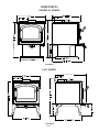
NorthAmerica’sBest
INSTALLATION, OPERATION, AND MAINTENANCE INSTRUCTIONS
QUADRA-FIRE 4300 SERIES
CONGRATULATIONS—You are now the proud owner of one of the finest stoves in the world for your home—the
QUADRA-FIRE. Now, before installing your stove and building your first fire—record the serial number on the
warranty card. Serial number is located on the safety label on the rear of the stove.
PLEASE READ ALL OF THE OWNERS MANUAL AND SAFETY NOTES
IMPORTANT SAFETY NOTES:
1.
2.
3.
4.
5.
6.
7.
8.
9.
10.
11.
12.
13.
14.
15.
16.
17.
When installing your stove, particular attention should be paid to fire protection. If this unit is not properly installed, a
house fire may result. For your safety, follow the installation instructions and contact local building or fire officials
about restrictions and installation inspection requirements in your area.
Never use gasoline or similar liquids to start a fire in this unit. Keep all such liquids well away from stove.
During operation, if any part of the stove starts to glow, the stove is in an overfired condition. Close the air controls
completely until the glowing has stopped. OVERFIRING VOIDS WARRANTY.
Cool ashes should be disposed of carefully, using a metal container.
Do not burn wet or green wood. Store wood in dry location.
Do not burn garbage, treated wood, or wood with salt (driftwood, etc.). Burning materials other than wood (including
charcoal) under adverse conditions may generate carbon monoxide in the home, resulting in illness or possible death.
Do not permit creosote or soot to accumulate excessively in the chimney or inside the firebox.
Check your chimney system thoroughly when installing into an existing metal or masonry chimney. Seek professional
advice if in doubt about its condition.
Do not connect this unit to a chimney flue already serving another appliance.
Comply with all minimum clearances to combustibles as shown in this manual for this appliance.
Build fire on brick firebox floor. Do not use grates, andirons or other method to support fuel.
HOT WHILE IN OPERATION. Keep children, pets, clothing and furniture away. Contact can cause skin burns.
Do not connect to any air distribution duct or system.
RISK OF FIRE! Do not operate with stove door or ash removal system door open.
For further information refer to NFPA 211 (U.S.) or CAN/CSA-B365 (Canada).
WARNING: WHEN ASSEMBLING A UNIBODY APPLIANCE, USE ONLY GENUINE ALADDIN HEARTH
PRODUCTS MANUFACTURED COMPONENTS. USE OF ANY OTHER COMPONENTS WILL VOID YOUR
WARRANTY, AND COULD PRESENT A SERIOUS SAFETY HAZARD.
WARNING: DO NOT OPERATE YOUR QUADRA-FIRE STOVE BEFORE FULLY ASSEMBLING ALL
COMPONENTS. BURNING YOUR STOVE WITHOUT A PEDESTAL OR LEG KIT ATTACHED WILL VOID
YOUR WARRANTY, AND COULD PRESENT A SERIOUS SAFETY HAZARD.
(Revised 01/1999)
401 N. WYNNE
COLVILLE, WA
99114
SAVE THESE INSTRUCTIONS
www.aladdinhearth.com
[email protected]
Part #250-2331 #832-3060
TABLE OF CONTENTS
Safety label ......................................................................................................................................... 3
Dimensions ......................................................................................................................................... 4
Clearances to combustibles ................................................................................................................ 6
Safety listing ....................................................................................................................................... 7
Installation materials needed .............................................................................................................. 7
Venting system ................................................................................................................................... 7
Chimney connector ............................................................................................................................ 8
Chimney height/draft.......................................................................................................................... 8
Connection to a masonry chimney ..................................................................................................... 8
1. Chimney .................................................................................................................................. 8
2. Thimble ................................................................................................................................... 11
A. Brick chimney thimble assembly ..................................................................................... 11
B. 6" solid pack chimney with metal supports ...................................................................... 12
Connection to a metal prefabricated chimney .................................................................................... 14
Mobile home installation .................................................................................................................... 15
Outside air kit installation .................................................................................................................. 16
Pedestal and leg installation ............................................................................................................... 17
Ash removal system installation ........................................................................................................ 18
Ash removal system operating and cleaning ...................................................................................... 19
Operating instructions ........................................................................................................................ 20
Burning process .......................................................................................................................... 20
Primary and secondary air systems ............................................................................................. 20
Blower operating instructions ..................................................................................................... 21
Operating tips .............................................................................................................................. 21
Burning guidelines ...................................................................................................................... 21
Building a fire ............................................................................................................................. 22
Wood selection and storage ........................................................................................................ 22
Maintenance ....................................................................................................................................... 23
Creosote ...................................................................................................................................... 23
Care and cleaning of glass and plated surfaces ........................................................................... 23
Chimney cleaning ....................................................................................................................... 23
Ash removal ................................................................................................................................ 23
Firebrick ...................................................................................................................................... 23
Overfiring .................................................................................................................................... 23
Door handle assembly and glass replacement .................................................................................... 24
Brick baffle replacement .................................................................................................................... 25
Brick pattern ....................................................................................................................................... 25
Installation of optional blower ........................................................................................................... 26
Top heat shield installation ................................................................................................................ 27
Accessory and service parts ............................................................................................................... 27
Warranty ............................................................................................................................................. 28
Warranty card ..................................................................................................................................... Insert
Page 2
4300 SAFETY LABEL
(found on back of stove)
Model:
Quadra-Fire
4300
Page 3
Serial No.
DIMENSIONS
PEDESTAL MODEL
FIGURE 1a
LEG MODEL
28 3 /8 " (72 1m m )
FIGURE 1b
Page 4
DIMENSIONS
STEP TOP PEDESTAL MODEL
7
33
2 13/16" (71mm)
10" (245mm)
FIGURE 2b
STEP TOP LEG MODEL
2 1 3 /1 6 " (7 1 m m )
1 0 " (2 5 4 m m )
FIGURE 2b
Page 5
CLEARANCES TO COMBUSTIBLES (UL AND ULC)
G
8
FLOOR PROTECTOR: Floor
protector must be noncombustible
material or equivalent, extending
beneath heater and to the front/
sides/rear as indicated.
NOTE: A 3/8” (10mm) minimum
thickness tile or equivalent is
recommended, but not required.
Minimum clearances to Combustible Materials (in inches and millimeters) for Quadra-Fire 4300 Series
Chimney &
Installation
Clearance
Connector
A
B
C
D
E
F
G
Residential
Standard
Note 1
19”(483) 32”(813)
21”(533) 16”(406) 22”(559) 12”(305) 52”(1321)
Residential/Mobile Home
Reduced
Note 2
10”(254) 27”(586)
18”(457) 7”(178)
17”(432) 9”(229) 52”(1321)
Alcove
Standard
Note 2 & 3
10”(254) 27”(586)
18”(457) 7”(178)
17”(432) 9”(229) 52”(1321)
Minimum clearances to Combustible Materials (in inches and millimeters) with top shield
Minimum clearances to Combustible Materials (in inches and millimeters) for Quadra-Fire 4300 Step Top
Chimney &
Installation
Clearance
Connector
A
B
C
D
E
F
Residential
Standard
Note 1
19”(483) 32”(813)
18”(457) 16”(406) 22”(559) 9”(229)
Residential/Mobile Home
Reduced
Note 2
10”(254) 27”(686)
12”(305) 7”(178)
17”(432) 3”(76)
Alcove
Standard
Note 2 & 3
10”(254) 27”(686)
12”(305) 7”(178)
17”(432) 3”(76)
G
52”(1321)
52”(1321)
52”(1321)
Minimum clearances to Combustible Materials (in inches and millimeters) with extended top shield
Chimney &
Installation
Clearances
Connector
A
B
C
D
E
F
Residential
Standard
Note 1
15”(381) 24”(610)
18”(457) 12”(305) 14”(356) 9”(229)
Residential/Mobile Home
Reduced
Note 2
10”(254) 24”(610)
12”(305) 7”(178)
14”(356) 3”(76)
Alcove
Standard
Note 2 & 3
10”(254) 24”(610)
12”(305) 7”(178)
14”(356) 3”(76)
G
52”(1321)
38”(966)
38”(966)
Note 1: 6” (152mm) diameter single wall, minimum 24 MSG black or blued steel connector pipe with a listed factory-built type HT
chimney suitable for use with solid fuels or a masonry chimney.
Note 2: 6” (152mm) diameter double wall insulated connector pipe with listed factory-built type HT chimney or a masonry chimney.
(Mobile home venting system must be equipped with a rain cap and spark arrestor.) For installations with a preexisting class A
chimney system, a listed stainless steel chimney liner should be installed, or the existing chimney examined by a chimney sweep for
acceptable further use.
Note 3: Alcove specifications: Maximum depth of alcove shall be no more than 48” (1219mm). For additional alcove information
and clearances, refer to clearances to combustibles above.
NOTE: Unit is approved for use with listed double wall air-insulated chimney connector or elbows.
When locating your stove consider safety, convenience, traffic flow, and the fact that the stove will need a chimney and chimney
connector.
FLOOR PROTECTION: Floor protector must be noncombustible material, extending beneath heater and to the front/sides/rear as
indicated.
NOTE: A 3/8” (10mm) minimum thickness tile or equivalent is recommended, but not required.
NFPA 211: Use a noncombustible material with 1” (25mm) ventilated air space to reduce clearances. However, this is not to exceed
50% of Quadra-Fire’s specified clearances.
NOTE: Must follow NFPA 211 spacing and materials to qualify. It is also subject to local jurisdiction.
AVOID FIRE: Maintain the designated clearances to combustibles. Insulation must not touch the chimney. You must maintain the
designated air space clearance around the chimney. This space around a chimney is necessary to allow natural heat removal from the
area. Insulation in this space will cause a heat buildup, which may ignite wood framing.
Page 6
SAFETY LISTING
The Quadra-Fire 4300 is safety listed by OMNI-Test Laboratories, Inc., Beaverton, Oregon, to UL 1482 and
ULC S627. It is also approved for mobile home installations with outside combustion air in the U.S. (see pages
15 and 16 for further details). For residential installations in Canada without an outside combustion air kit, a
source of fresh air into the room must be provided.
INSTALLATION MATERIALS NEEDED FOR YOUR SAFETY
CHIMNEY CONNECTOR (also known as flue pipe or stove pipe): The chimney connector joins the stove to
the chimney (see page 8). It should be 6” (152mm) minimum diameter 24 MSG black or blued steel, or an
approved air-insulated double wall venting pipe.
THIMBLE: A manufactured or site-constructed device installed in combustible walls through which the
chimney connector passes to the chimney (see page 11-13). It is intended to keep the walls from igniting.
CHIMNEY SYSTEMS:
A. APPROVED MASONRY (see specifications on pages 8-13) with at least 5/8” (16mm) fire clay lining
joined with refractory cement or other listed system suitable for use with wood stoves.
B. PREFABRICATED 6" (152mm) listed high temperature (UL 103HT or ULC 629M) chimney. Components
required by manufacturers for installation such as the chimney support base, firestop (as appropriate), attic
insulation shield, insulated tee, etc., are necessary to assure a safe chimney installation. Use only
components manufactured for the chimney. Chimney installation should meet NFPA 211 standards.
FIRE SAFETY: To provide reasonable fire safety, the following should be given serious consideration:
1. Install at least one smoke detector on each floor of your home to ensure your safety. They should be
located away from the heating appliance and close to the sleeping areas. Follow the smoke detector
manufacturer’s placement and installation instructions, and be sure to maintain regularly.
2. A conveniently located Class A fire extinguisher to contend with small fires resulting from burning embers.
3. A practiced evacuation plan, consisting of at least two escape routes.
4. A plan to deal with a chimney fire as follows:
In the event of a chimney fire:
A. Notify fire department
B. Prepare occupants for immediate evacuation.
C. Close all openings into the stove.
D. While awaiting fire department, watch for ignition of adjacent combustibles from overheated stove pipe,
hot embers or sparks from the chimney.
VENTING SYSTEM
The venting system consists of a chimney connector and a chimney. These get extremely hot during use.
Temperatures inside the chimney may exceed 2000°F (1100°C) in the event of a creosote fire. To protect
against the possibility of a house fire, the chimney connector and chimney must be properly installed and
maintained. An approved thimble must be used when a connection is made through a combustible wall to a
chimney. A chimney support package must be used when a connection is made through the ceiling to a
prefabricated chimney. These accessories are absolutely necessary to provide safe clearances to combustible
wall and ceiling material. Follow venting manufacturer’s clearances when installing venting system.
This stove may be connected to a lined masonry chimney or a listed high temperature prefabricated approved
metal chimney. Do not connect it to a chimney serving another appliance. To do so will affect the safe
operation of both appliances.
Page 7
CHIMNEY CONNECTOR
The chimney connector must be 6” (152mm) diameter with a minimum thickness of 24 gauge. Do not use
aluminum or galvanized steel. They cannot properly withstand the extreme temperatures of a wood fire. Do not
use chimney connector pipe as a chimney. You must connect your stove to a chimney comparable to those
illustrated in this manual.
Chimney connector sections must be attached to the stove and to each other with the crimped end toward the
stove (Figure 3). This allows creosote to run into the stove and not onto the outside of the pipe. Attach the
chimney connector to the flue collar with three sheet metal screws. All joints should also be secured with three
sheet metal screws. Otherwise, in the event of a creosote fire, the connector may vibrate apart.
FIGURE 3
For proper operation, the chimney connector should be as short as possible. Horizontal lengths of chimney
connector should have a minimum upward slope from the stove of at least ¼” per foot.
CHIMNEY HEIGHT/DRAFT
To insure that your Quadra-Fire stove burns properly, the chimney draft (static pressure) should be
approximately 0.1” water column (W.C.) during a high burn and .04” W.C. during a low burn, measured 6”
(152mm) above the top of the stove after one hour of operation at each burn setting.
NOTE: These are guidelines only, and may vary somewhat for individual installations.
Your Quadra-Fire stove was designed for and tested on a 6” (152mm) chimney, 12’-14’ (3.66-4.27m) high,
measured from the top of the stove. The further your stack height or diameter varies from this configuration,
the probability of performance problems increases. In addition, exterior conditions such as roof line,
surrounding trees, prevailing winds and nearby hills can influence stove performance.
CONNECTION TO A MASONRY CHIMNEY
1. CHIMNEY: Should the stove be connected to a masonry chimney, the chimney should be examined for
cracks, loose mortar, or other signs of deterioration and blockage. The stove should not be installed until it
is determined that the chimney is safe for use. Since an oversized flue contributes to the accumulation of
creosote, the size of the flue should be checked to determine that it is not too large for the stove. The
chimney should also be checked to insure it meets the minimum standards of the National Fire Protection
Association (NFPA) Standard 211. Following is a list of the more critical minimum requirements for a
properly constructed chimney.
The masonry wall of the chimney, if brick or modular block, must be a minimum of 4” (102mm) thick. A
mountain or rubble stone wall must be at least 12” (305mm) thick.
Page 8
The chimney must have a fire clay flue liner (or equivalent) with a minimum thickness of 5/8” (16mm) and
must be installed with refractory mortar. There must be at least ½” (13mm) air space between the flue liner and
the chimney wall (Figure 4). An equivalent liner must be a listed chimney liner system or other approved
material.
FIGURE 4
A chimney inside the house must have at least 2” (50mm) of clearance to the combustible structure. A chimney
outside the house must have at least 1” (25mm) clearance to the combustible structure. Firestops must be
installed in the spaces where the chimney passes through floors and/or ceiling (Figure 5).
FIGURE 5
Page 9
Remember that insulation must not contact the chimney. There must be air space around the chimney.
Insulation must be 2” (50mm) or more from the chimney (Figure 6).
FIGURE 6
A chimney must be the required height above the roof or other obstruction for safety and proper draft operation.
The chimney must be a minimum of 3’ (914mm) higher than the highest point where it passes through the roof,
and at least 2’ (610mm) higher than the highest part of the roof or structure that is within 10’ (3048mm) of the
chimney, measured horizontally (Figure 7).
FIGURE 7
Page 10
2. THIMBLE: An approved thimble must be used when the connection from the stove is made through a
combustible wall to a masonry chimney. There are several methods you can use for connection through a
combustible wall, two of which are illustrated in this manual. For additional methods, consult local building
authorities or use the standards set forth in NFPA 211.
Also, listed prefabricated metal thimbles are available for use with wood stoves. The manufacturer’s
installation for the thimbles must be strictly followed to assure the safety of the system. Be sure to maintain
the designated clearances to combustible materials.
A. BRICK CHIMNEY THIMBLE ASSEMBLY: Construction of the brick thimble assembly requires
12” (305mm) of brick around a fire clay liner. Be sure the point of penetration allows an 18” (457mm)
clearance from the connector to the ceiling. For a 6” (152mm) chimney connector, an opening of 30”
(762mm) must be cut in the wall to maintain the required 12” (305mm) of brick separation from
combustibles. It will be necessary to cut wall studs and install a header and sill frame to maintain proper
dimensions and to hold the weight of the brick (Figure 8).
FIGURE 8
Page 11
FIGURE 9
Minimum 3 ½” (89mm) [4” (102mm) nominal] thick solid bricks are to be used. The fire clay liner
(ASTM C35 or equivalent), 5/8” (16mm) wall thickness, must not penetrate into the chimney beyond the
inner surface of the chimney flue liner and must be firmly cemented in place. If it is necessary to cut a
hole in the chimney liner, use extreme care to keep it from shattering. Refractory mortar must be used at
the junction with the chimney liner. After the assembly is complete, insert the chimney connector into
the fire clay liner. Do not push it beyond the inside edge of the chimney liner, as this will affect the
draw of the chimney.
B. 6” SOLID PACK CHIMNEY WITH METAL SUPPORTS AS A THIMBLE: For the method of
installation to a masonry chimney shown in Figures 10 and 11 (page 13), it will be necessary to purchase
a 6” (152mm) inside diameter, 12” (305mm) long section of prefabricated listed solid pack chimney to
use as a thimble. Purchase a wall spacer, trim collar and wall band that are manufactured to fit the
chimney section you purchase.
The safety features of this system are the 2” (50mm) air space between the chimney section and
combustible wall, and the 1” (25mm) air space around the chimney connector as it passes through the
chimney section to the chimney. The location of the opening through the wall to the chimney must
leave a minimum 18” (457mm) vertical clearance between the connector pipe and the ceiling, to prevent
the ceiling from catching fire when using single wall pipe.
Cut out a 14 ½” (368mm) diameter opening in the wall. It may be necessary to cut wall studs and install
a header and sill frame to maintain the wall support. The hole in the chimney must have at least a 6”
(152mm) diameter fire clay liner or equivalent, secured with refractory mortar. If it is necessary to cut a
hole in the chimney liner, use extreme care to keep it from shattering.
Page 12
First, build the frame for the thimble, making sure that it is no smaller than 14½” (368mm) diameter, which will
maintain a 2” (50mm) air space around the chimney section. Attach the wall spacer to the chimney side of the
frame. Then insert the frame into the opening, toe-nailing it to the wall studs. Install the wall band in the
framing to secure the chimney section in place. Insert a single section of chimney connector into the chimney
through the wall band, being sure it does not protrude into the chimney beyond the edge of the chimney flue
lining. Apply high temperature furnace cement to the end of the chimney section and install it over the
connector, through the wall band, and through the wall spacer. Tighten the wall band to hold the chimney
section firmly in place and against the chimney. Install the trim collar on the outside of the opening. Check to
insure there is a 1” (25mm) air space between the connector and the chimney section. Also, during installation,
always check to insure that a 2” (50mm) air space is being maintained to the wood framing. Do not fill this
space with insulation. Insulation in this air space will cause a heat buildup which may ignite the wood framing.
FIGURE 10
FIGURE 11
Page 13
CONNECTION TO A METAL PREFABRICATED CHIMNEY
When a metal prefabricated chimney is used, the manufacturer’s installation instructions must be followed
precisely. You must also purchase (from the same manufacturer) and install the ceiling support package or wall
pass-through and “T” section package, firestops (where needed), insulation shield, roof flashing, chimney cap,
etc. Maintain the proper clearance to the structure as recommended by the manufacturer. This clearance is
usually a minimum of 2” (50mm), although it may vary by manufacturer or for certain components.
There are basically two methods of metal chimney installation. One method is to install the chimney inside the
residence through the ceiling and the roof (Figure 12). The other method is to install an exterior chimney that
runs up the outside of the residence (Figure 13). The components illustrated may not look exactly like the
system you purchase, but they demonstrate the basic components you will need for a proper and safe
installation.
The chimney must be the required height above the roof or other obstruction for safety and proper draft
operation. The chimney must be a minimum of 3’ (914mm) higher than the highest point where it passes
through the roof, and at least 2’ (610mm) higher than the highest part of the roof or structure that is within 10’
(3048mm) of the chimney, measured horizontally (Figure 5, page 9).
REMEMBER: Follow the manufacturer’s installation instructions and maintain the manufacturer’s specified
clearance distances.
FIGURE 12
INTERIOR CHIMNEY,
RUNNING
THROUGH CEILING AND ROOF
Page 14
FIGURE 13
EXTERIOR CHIMNEY RUNNING UP
THE OUTSIDE OF THE RESIDENCE
*Note: Unit has not been tested with
a horizontal connector. Refer
to local building codes.
MOBILE HOME INSTALLATION
You must use a Quadra-Fire 4300 outside air kit (see page 16 for part numbers) for installation in a mobile
home. Use of alternative material will void warranty.
1. An outside air inlet must be provided for combustion and be unrestricted while unit is in use.
2. Unit must be secured to the mobile home structure by bolting pedestal through hearth pad and into floor.
For leg models, use attachment brackets to attach stove through pad and into floor.
3. Do not install unit in a sleeping room.
4. The structural integrity of the mobile home floor, walls, and ceiling/roof must be maintained (i.e., do not
cut through floor joist, wall stud, ceiling truss, etc.).
5. Unit must be grounded with #8 copper grounding wire or equivalent and terminated at each end with
N.E.C. approved grounding device.
6. Refer to clearance to combustibles section (page 6) for listing to combustibles.
7. Seal all wall/floor inlets to prevent air or moisture penetration. Check periodically to insure the inlet is free
of obstructions (e.g., snow or ice).
8. Burn wood only. Other types of fuels may generate poisonous gases (e.g., carbon monoxide).
9. If unit burns poorly while exhaust blower is on in home, increase combustion air.
NOTE: Offsets from the vertical, not exceeding 45°, are allowed per Section 905(a) of the Uniform
Mechanical Code (UMC). Offsets greater than 45° are considered horizontal and are also allowed,
providing the horizontal run does not exceed 75% of the vertical height of the vent. Construction,
clearance and termination must be in compliance with the UMC Table 9C. This installation also
complies with NFPA 211.
Page 15
OUTSIDE AIR KIT INSTALLATION
4300 LEG MODELS
1.
2.
3.
4.
5.
Part #831-1740
Front cover plate attaches to firebox bottom below ash lip with two ¼”-20 mounting screws.
Mount rear air intake cover plate with two mounting screws.
Install each side cover with two 8-32 screws.
Floor installation: Cut a 3” (76mm) minimum hole in the floor to accommodate outside air piping. Use 3” (76mm)
metal flex or rigid piping to directly connect outside air to the unit or into vented crawl space. 4” (102mm) pipe is
recommended on a 10’ (3048m) run or longer. (Obtain an adapter from the venting manufacturer to change from 3”
to 4” pipe.) Use the rodent screen supplied to cover the hole in the floor or at the outside opening. Seal between the
floor and the pipe with silicone to prevent moisture penetration.
Rear/wall installation: Cut a 3” (76mm) hole in outside wall to accommodate outside air piping. Use 3” (76mm)
metal flex or rigid piping to directly connect outside air to stove intake. Use a termination cap equipped with a
rodent screen (obtain from venting manufacturer). Seal between the wall and the pipe with silicone to prevent
moisture penetration.
Rear air intake
cover plate
Side cover
Front cover
Front cover
4300 PEDESTAL MODELS
1.
2.
3.
Part #831-1730
Kit includes two 1” (25mm) rope gaskets to be tucked under pedestal to seal off both sides.
Floor installation: Cut a 4” (102mm) minimum hole in the floor to accommodate outside air piping. Use 4”
(102mm) minimum metal flex or rigid pipe to directly connect outside air to the unit or into vented crawl space.
Install rear cover over hole in rear of pedestal. Use the rodent screen supplied to cover the hole in the floor or at the
outside opening. Seal between the floor and the pipe with silicone to prevent moisture penetration.
Rear/wall installation: Cut a 4” (102mm) hole in outside wall to accommodate outside air piping. Install rear inlet
with four screws. Use a 4” (102mm) metal flex or rigid piping to directly connect outside air to stove intake. Use a
termination cap equipped with a rodent screen (obtain from venting manufacturer). Seal between the wall and the
pipe with silicone to prevent moisture penetration.
Rear inlet (wall)
Rope gasket
Rodent screen
Rear cover (floor)
Page 16
Rope gasket
PEDESTAL/LEG KIT INSTALLATION
WARNING: DO NOT OPERATE YOUR QUADRA-FIRE STOVE BEFORE FULLY ASSEMBLING ALL
COMPONENTS. BURNING YOUR STOVE WITHOUT A PEDESTAL OR LEG KIT ATTACHED WILL VOID
YOUR WARRANTY, AND COULD PRESENT A SAFETY HAZARD.
PEDESTAL MODEL
1.
2.
3.
4.
5.
6.
7.
8.
Place protective pad or stove pallet on floor.
Lay body of stove on its back on protective pad or pallet.
Slide pedestal over adapter on bottom of stove
Line up holes in sides of pedestal with holes in adapter.
Bolt pedestal into place, and tighten securely.
Carefully stand stove up and place in desired location.
Slip wooden decorative strips onto pedestal edges.
Open door of stove and check to insure firebricks and kaowool blanket are in
their proper locations (see page 25).
FOR INSTALLATION OF
ASH REMOVAL
SYSTEM, SEE PAGE 18.
Adapter
Pedestal
LEG MODEL
1.
2.
3.
4.
5.
6.
7.
8.
Place protective pad or stove pallet on floor.
Lay body of stove on its back on protective pad or pallet.
Bolt cover piece onto mounting brackets, using inner two mounting holes.
Slip washers onto bolts, then bolt legs onto mounting brackets.
Screw leg assembly onto adapter on bottom of stove using eight ¼”-20 screws.
Carefully stand stove up and place in desired location.
Use leveling bolts on legs to stabilize and level stove.
Open door of stove and check to insure firebricks and kaowool blanket are in
their proper locations (see page 25).
Mounting bracket
Cover piece
Adapter
Leg
Page 17
ASH REMOVAL SYSTEM INSTALLATION
1. Remove ash removal system top and
bottom cover plates by loosening nuts
under stove.
2. Discard both plates.
3. Insert ash removal system grate into
opening in firebox floor.
4. Continue with proper installation
according to model you have purchased:
pedestal or leg.
PEDESTAL MODELS
1. Place protective pad on floor.
2. Lay body of stove on its back on protective
pad.
3. Line up holes in ash removal system with
holes in adapter on bottom of stove.
4. Screw ash removal system securely in
place.
5. Slide pedestal over ash removal system,
and line up holes in sides of pedestal with
holes in adapter on bottom of stove.
6. Screw pedestal into place, and tighten
securely.
7. Carefully stand stove up and place in
desired location.
8. Slip wooden decorative strips onto pedestal
edges.
9. Open door of stove and check to insure
firebricks and kaowool blanket are in
their proper locations (see page 25).
LEG MODELS
1. Place protective pad on floor.
2. Lay body of stove on its back on protective
pad.
3. Line up holes in ash removal system with
holes in adapter on bottom of stove.
4. Screw ash removal system in place.
5. Bolt cover pieces onto mounting brackets,
using outer two mounting holes.
6. Slip washers onto bolts, then bolt legs onto
mounting brackets.
7. Screw leg assembly onto adapter on
bottom of stove using eight ¼”-20 screws.
8. Carefully stand stove up and place in
desired location.
9. Use leveling bolts on legs to stabilize and
level stove.
10. Open door of stove and check to insure
firebricks and kaowool blanket are in
their proper locations (see page 25).
Page 18
ASH REMOVAL SYSTEM OPERATING AND CLEANING
CAUTION: Do not operate stove with ash removal system door open. Store ash in metal container until hot
embers have cooled completely.
1.
2.
3.
4.
5.
6.
7.
When stove is cool, open front door and brush most of the ash into the center of the firebox. Remember to
leave ¼” to ½” (6-13mm) of ash on the firebox floor to act as a natural grate, allowing air to flow freely
underneath wood.
Clean ash down through the ash removal system grate into the drawer below. If there are large pieces in the
ashes, you can remove the grate before cleaning the ash into the drawer. Be sure to replace the grate before
operating the stove.
Release catches on sides of ash removal door.
Pull out ash drawer. Close ash removal door. (Closing this door avoids ash blowing into the room in the
event of a downdraft.)
Empty ashes into metal container. Store container on non-combustible surface until ashes are cool enough
to dispose.
Open ash removal door and replace ash drawer, making sure handle faces forward.
Close ash removal door and fasten catches.
LEG MODEL
PEDESTAL MODEL
Page 19
OPERATING INSTRUCTIONS
IMPORTANT - PLEASE READ BEFORE USING STOVE
BURNING PROCESS
In recent years there has been an increasing concern about air quality. Much of the blame for poor air quality has been
placed on the burning of wood for home heating. In order to improve the situation, we at Quadra-Fire have developed
cleaner-burning wood stoves that surpass the requirements for emissions established by our governing agencies. These
wood stoves, like any other appliances, must be properly operated in order to insure that they perform the way they are
designed to perform. Improper operation can turn most any wood stove into a smoldering environmental hazard.
It helps to know a little about the actual process of burning in order to understand what goes on inside a stove. The first
stage of burning we will call the kindling stage. In this stage, the wood is heated to a temperature high enough to evaporate the moisture which is present in all wood. The wood will reach the boiling point of water (212°F) and will not get
any hotter until the water is evaporated. This process takes heat from the coals and tends to cool the stove. Fire requires
three things to burn: fuel, air and heat. So, if heat is robbed from the stove during the drying stage, the new load of wood
has reduced the chances for a good clean burn. For this reason, it is always best to burn dry, seasoned firewood. When
the wood isn’t dry, you must open the air controls and burn the stove at a high burn setting for a longer time to start it
burning. The control on the right side of the stove is called the primary control; it is used mainly during the kindling
stage of burning, or when burning the stove at a high burn setting. It should be closed (pulled outward) for lower burns.
The next stage of burning, the secondary stage, is the period when the wood gives off flammable gases which burn above
the fuel with bright flames. During this stage of burning it is very important that the flames be maintained and not
allowed to go out. This will insure the cleanest possible fire. If you are adjusting your stove for a low burn rate, you
should close down the air to the point where you can still maintain some flame. If the flames tend to go out, the stove is
set too low for your burning conditions. The air control in the center of the stove, beneath the ashcatcher, is the one used
to adjust the stove for lower burn rates. This is called the secondary control. Pulling either control towards you closes it,
pushing it in opens it.
The final stage of burning is the charcoal stage. This occurs when the flammable gases have been mostly burned and
only charcoal remains. This is a naturally clean portion of the burn. The coals burn with hot blue flames. It is very
important to reload your stove while enough lively hot coals remain in order to provide the amount of heat needed to dry
and rekindle the next load of wood. It is best to open the air controls for a short while before reloading. This livens up
the coalbed. You should also break up any large chunks and distribute the coals so that the new wood is laid on hot coals.
Air quality is important to all of us, and if we choose to use wood to heat our homes we should do so responsibly. To do
this we need to learn to burn our stoves in the cleanest way possible. Doing this will allow us to continue using our wood
stoves for many years to come.
PRIMARY AIR SYSTEM
The primary combustion air enters at the rear of the firebox through the primary air tubes. This air supply is controlled
by the primary control. For maximum burn rates (more heat) push control in, for minimum burn rates (less heat) pull
control out.
SECONDARY AIR SYSTEM
The secondary air enters at the upper front of the firebox, near the top of the glass door. This preheated air supplies the
necessary fresh oxygen to mix with the unburned gases, helping to create secondary, tertiary and quaternary combustions.
This air is regulated by the secondary control. For more secondary air push control in, for less secondary air pull control
out.
Primary control
Secondary control
Page 20
OPERATING INSTRUCTIONS (cont.)
BLOWER OPERATING INSTRUCTIONS
(see blower installation instructions on page 26)
If your Quadra-Fire wood stove is equipped with an optional blower, you should follow these guidelines:
1. Initial (cold) start-up: Leave blower off until your stove is hot and a good coalbed is established. The blower may
be turned on approximately 30 minutes after loading the stove with fuel.
2. High burn setting: The blower may be left on throughout the burn.
3. Medium burn setting: The blower should be left off until a good burn is established, then turned on at a medium or
high rate.
4. Low burn setting: The blower tends to cool off the stove. If you are using wet wood or a very low burn setting,
leave blower off until the burn is well established. Then, if you wish, turn the blower on at a lower rate. Too high a
blower setting with a low burn rate may adversely affect emissions.
5. The blower is equipped with a speed control. The highest blower speed is obtained by turning the speed control on
and then adjusting back towards off as far as possible without turning the blower off. For a low blower speed, turn
the control knob clockwise as far as possible.
OPERATING TIPS
Here are a few tips on operating your Quadra-Fire stove to obtain maximum efficiency with lowest emissions:
1. Regardless of desired heat output, when loading stove, burn your Quadra-Fire with both air controls wide open for a
minimum of 15 minutes.
2. Regulate burn rate (heat output) by using the secondary control (center, under ashcatcher). The primary control (on
the right) is mainly for initial start-up, reloading, or high burns.
3. Heat output settings: Following 15 minutes of burning with controls wide open (see #1 above):
BTU/Hr.
Below 10,000
10,000-15,000
15,000-30,000
Maximum heat
Primary
Closed after 5 minutes
Closed after 5 minutes
Closed after 5 minutes
Full open
Secondary
Pull to stop
¾” - 1” open
1” - 2½” open
Full open
These are approximate settings, and will vary with type of wood or chimney draft.
4. Burn dry, well-seasoned wood (see section on wood selection and storage, page 22).
BURNING GUIDELINES
Aladdin Hearth Products is deeply concerned with the air quality in your community. In order to maintain clean air, it is
very important to burn your wood stove in the most efficient manner possible. Following these guidelines will insure
environment-friendly operation.
OPACITY
This is the measure of how cleanly your stove is burning. Opacity is measured in percent; 100% opacity is when an
object is totally obscured by the smoke column from a chimney, and 0% opacity means that no smoke column can be
seen. As you become familiar with your stove, you should periodically check the opacity. This will allow you to know
how to burn your stove as nearly smoke-free as possible (goal of 0% opacity).
WOOD
Burn only dry seasoned wood. Store wood under cover, out of the rain and snow.
BURN RATES
HIGH: Open (push in) both controls fully. It is important to do this when reloading the stove. Failure to do this could
result in excessive emissions (opacity).
Page 21
OPERATING INSTRUCTIONS (cont.)
BURNING GUIDELINES (cont.)
MEDIUM: After a wood load has been burning on high for at least 15 minutes (longer for very large pieces or wet
wood), close (pull out) the primary control (on the right side of the stove). Leave the secondary control (under the
ashcatcher) open (pushed in).
LOW: After a wood load has been burning on high for at least 15 minutes (longer for very large pieces or wet wood),
close (pull out) the primary control. Then close down the secondary control, gradually making sure to maintain flames in
the stove. It is very important to maintain flames in your stove during the first few hours of a low burn, to avoid excessive air pollution.
BUILDING A FIRE
Before lighting your first fire in the stove, make certain that the baffle is correctly positioned. It should be resting on the
rear baffle support so that the hole in the baffle lines up with the baffle locating pin (see page 25 for baffle installation
instructions). Also refer to care and cleaning of plated surfaces section on page 23 before lighting your first fire.
There are many ways to build a fire. The basic principle is to light easily-ignitable tinder or paper, which ignites the fast
burning kindling, which in turn ignites the slow-burning firewood. Here is one method that works well:
1. Place several wads of crushed paper on the firebox floor.
2. Lay small dry sticks of kindling on top of the paper.
3. Open primary and secondary controls fully.
4. Make sure that no matches or other combustibles are in the immediate area of the stove. Be sure the room is adequately
ventilated and the flue unobstructed.
5. Light the paper in the stove. NEVER light or rekindle stove with kerosene, gasoline, or charcoal lighter fluid; the
results can be fatal.
6. Once the kindling is burning quickly, add several full-length logs 3” (76mm) or 4” (102mm) in diameter. Be careful
not to smother the fire. Stack the pieces of wood carefully: near enough to keep each other hot, but far enough away
from each other to allow adequate air flow between them.
7. When ready to reload the stove, add more logs. Large logs burn slowly, holding a fire longer. Small logs burn fast
and hot, giving quick heat.
8. Adjust the primary and secondary air controls; the more you close down the controls, the lower and slower the fire
will burn. The more open the controls, the more heat will be produced.
As long as there are hot coals, repeating steps 7 and 8 will maintain a continuous fire throughout the season.
NOTE: The special high temperature paint that your stove is finished with will cure as your stove heats. You will notice
an odor and perhaps see some vapor rise from the stove surface; this is normal. We recommend that you open a window
until the odor dissipates and paint is cured.
NOTE: On a cold start-up, you may see a small amount of smoke coming from the underside of the stove until chimney
draft is established. This is normal, and will stop when the loading door is closed.
WOOD SELECTION AND STORAGE
Dry and well-seasoned wood will not only minimize the chance of creosote formation, but will give you the most efficient fire. Even dry wood contains at least 15% moisture by weight, and should be burned hot enough to keep the chimney hot for as long as it takes to dry the wood out - about one hour. It is a waste of energy to burn unseasoned wood of
any kind. Dead wood lying on the forest floor should be considered wet, and requires full seasoning time. Standing dead
wood can be considered to be about two-thirds seasoned. To tell if wood is dry enough to burn, check the ends of the
logs. If there are cracks radiating in all directions from the center, it is dry. If your wood sizzles in the fire, even though
the surface is dry, it may not be fully cured. Splitting wood before it is stored reduces drying time. Wood should be
stacked so that both ends of each piece are exposed to air, since more drying occurs through the cut ends than the sides.
This is true even with wood that has been split. Store wood under cover, such as in a shed, or covered with a tarp, plastic,
tar paper, sheets of scrap plywood, etc., as uncovered wood can absorb water from rain or snow, delaying the seasoning
process.
Page 22
MAINTENANCE
CREOSOTE
1. Formation and need for removal: When wood is burned slowly, it produces tar and other organic vapors which
combine with expelled moisture to form creosote. The creosote vapors condense in the relatively cool chimney flue of
a newly-started or a slow-burning fire. As a result, creosote residue accumulates on the flue lining. When ignited, this
creosote creates an extremely hot fire which may damage the chimney or even destroy the house. The chimney
connector and chimney should be inspected at least twice monthly during the heating season to determine if a creosote
buildup has occurred. If creosote has accumulated, it should be removed to reduce the risk of a chimney fire.
2. Inspection: Inspect the system at the stove connection and at the chimney top. Cooler surfaces tend to build creosote
deposits quicker, so it is important to check the chimney from the top as well as from the bottom.
3. Removal: The creosote should be removed with a brush specifically designed for the type of chimney in use. A
chimney sweep can perform this service. It is also recommended that before each heating season the entire system be
professionally inspected, and cleaned and repaired if necessary.
CARE AND CLEANING OF GLASS
NOTE: Remove all labels from glass before lighting the first fire in your stove.
Quadra-Fire stoves are equipped with ceramic super heat-resistant glass, which can only be broken by impact or misuse.
Do not slam stove door or impact the glass. When closing door, make sure that logs do not protrude against the glass.
Clean glass with a nonabrasive glass cleaner, such as Windex. Abrasive cleaners may scratch and cause glass to crack.
Inspect glass regularly. If you find a crack or break, immediately put the fire out and return the door to your dealer for
replacement of glass before further use. Leaving the primary air control open during the entire burn will cause overfiring.
Overfiring the appliance may cause crazing, a white non-removable film on inside of glass. Overfiring voids warranty.
NOTE: Replace with ceramic glass only.
CARE AND CLEANING OF PLATED SURFACES
Clean 24 karat gold-plated surfaces with warm soapy water, vinegar or a glass cleaner before lighting your first fire.
WARNING: When the appliance is equipped with a 24 karat gold-plated door, you must clean all the
fingerprints and oils from the gold surface before firing the appliance for the first time. Use a glass
cleaner or vinegar and towel to remove the oils. If not cleaned properly before lighting your first fire, the
oils can cause permanent markings on the gold plating. After the gold plating is cured, the oils will not
affect the finish and little maintenance is required: just wipe clean as needed.
CAUTION: Do not use polishes with abrasive agents. They will scratch the plating.
CHIMNEY CLEANING
Disconnect flue pipe from stove before cleaning chimney. Otherwise residue can pile up on top of the baffle, and the
stove will not work properly.
ASH REMOVAL
Remove cold ashes (NEVER HOT) from the stove by shoveling them into a metal container with a tight-fitting lid.
Spraying cold ashes with water before shoveling them out of the stove will help eliminate ash flying around the firebox
and into the room. Always treat ashes as if they contain hot coals, and store the container on a noncombustible floor
away from combustible material pending final disposal. If unit is equipped with an ash removal system, see page 19 for
operating instructions.
FIREBRICK
The firebox of your Quadra-Fire stove is lined with high quality firebrick, which has exceptional insulating properties.
There is no need for use a grate; simply build a fire on the firebox floor of your stove.
OVERFIRING
Do not overfire. Using flammable liquids or too much wood, burning trash in the stove, or allowing too much air into the
stove, may result in overfiring. If the chimney connector or stove glows red or even worse, white, the stove is overfired.
This condition may ignite creosote in the chimney, possibly causing a house fire. If you overfire, immediately close the
air controls and door, if open, to reduce the air supply to the fire.
Page 23
DOOR HANDLE ASSEMBLY
LATCH CAM
NOTE:
Spring handle not included in door
handle assembly. When replacing
door handle, either use old spring
handle or order new spring handle
separately.
GLASS REPLACEMENT
1.
2.
3.
4.
5.
6.
7.
Remove door from stove and lay on a padded flat surface.
Remove glass tabs and screws with a Phillips screwdriver (turn screws counterclockwise).
Lift glass frame pieces and glass out of the door frame.
Lay new glass with fiberglass tape around it into the door frame, making sure the Quadra-Fire logo reads
correctly to the outside.
Place glass frame pieces over the fiberglass tape on the edges of the glass. Be sure glass is centered in the
opening (i.e., same space top and bottom, left and right sides).
Reinstall screws and glass tabs tight enough to hold glass and frame in place. DO NOT OVERTIGHTEN.
Check again for centering of glass in door frame, and give all screws a final tightening.
Page 24
BRICK BAFFLE
Part #832-2330 Complete Baffle Brick Set (clay)
Part #832-2370 Single Baffle Brick (clay)
Part #832-2380 Front Baffle Support
Baffle is made of clay firebrick supported by
stainless steel brackets, and covered with a ½”
kaowool blanket which contacts the firebox on
the sides and back.
REPLACEMENT INSTRUCTIONS:
1.
Remove the manifold tube located second
from the rear of the firebox.
Place the two baffle brick (located second
from the rear) up onto the rear baffle brick.
Slide remaining baffle brick one at a time to
the resulting opening. Once brick is over
opening, lift one side up toward stove top and
drop the other side down free from middle
baffle support and into the firebox.
Kaowool blanket can now be removed out the
front of the stove, or dropped out through the
opening to the rear of the stove.
Reinstall kaowool blanket and baffle brick in
reverse order. Make sure that manifold tube is
secured in place, and that kaowool blanket is
resting flat on top of baffle.
2.
3.
4.
5.
BRICK PATTERN
Part #832-2360 Brick Set (4300 Unibody/ARS)
Part #832-0550 Brick, Single, Cut or Uncut
BACK
4.25" x 6.75"
BACK
BACK
4.5" X 9"
4.5" X 9"
BACK
4.25" X 6.75"
1.5" CUT OUTS
LEFT SIDE
BOTTOM
BOTTOM
4.5" X 9"
4.5" X 9"
4" X 9"
RIGHT SIDE
4" X 9"
BOTTOM
BOTTOM
3.625" X 9"
3.625" X 9"
LEFT SIDE
RIGHT SIDE
4.5" X 9"
4.5" X 9"
BOTTOM
BOTTOM
3.25" X 6"
3.25" X 6"
LEFT SIDE
4.5" X 9"
RIGHT SIDE
BOTTOM
BOTTOM
4.5" X 9"
4.5" X 9"
LEFT SIDE
4.5" X 9"
4.5" X 9"
RIGHT SIDE
BOTTOM
3.125" X 9"
BOTTOM
Page 25
3.125" X 9"
4.5" X 9"
INSTALLATION OF OPTIONAL BLOWER
Part #831-1700
The blower is shipped fully assembled and ready for installation.
1. Remove three ¼”-20 (3/8” hex head) bolts from blower cover, and remove nutbar. Discard nutbar.
2. Using bolts, attach blower to lower rear of stove, as shown.
3. Plug blower cord into a grounded outlet. Do not remove ground prong from plug. Route power cord to
avoid heat from the stove, or other damage.
4. Adjust the blower speed control to the desired speed.
BLOW ER SPEED CONTROL
BLOWER SWITCH ADJUSTMENTS
The blower speed control for this unit is adjusted at the factory, and should not require further adjustment.
When the speed control is turned clockwise, it will click on to high speed. Turn the speed control clockwise to
decrease the speed. At full clockwise, the blower should blow gently, but should not stop.
STEPS FOR ADJUSTING THE BLOWER SPEED CONTROL
1.
2.
3.
With the unit plugged in, turn the speed control knob to slow (full clockwise).
With a small screwdriver, adjust the blower speed by turning the adjustment mechanism through the hole
on the side of the speed control.
Adjust the speed so the blower runs slowly, but does not stop. Turn clockwise to slow the blower and
counterclockwise to increase the speed.
Page 26
TOP HEAT SHIELD INSTALLATION
1.
2.
3.
4.
Unscrew and remove the rear heat deflector.
Attach the two “S” clips to the upper edge of the outer wall of the stove.
Set top heat shield on stove and push down into “S” clips
Install chimney pipe through hole in top heat shield.
NOTE: SEE PAGE 6 FOR REDUCED CLEARANCES WITH STANDARD AND EXTENDED TOP SHIELD.
ACCESSORIES AND SERVICE PARTS
ACCESSORIES
831-1660
821-0292
831-1571
831-1730
831-1740
831-1700
832-1091
832-1911
832-0031
831-1670
SERVICE PARTS
Standard top shield, gold
Standard top shield, black
Extended top shield, black
Outside air kit, pedestal
Outside air kit, leg
Blower
Black door
Trim door
Gold door
Ash removal system
832-2400
832-2360
832-2370
832-2330
832-2380
832-0060
832-0540
832-1680
832-0620
832-0630
832-0500
832-2510
Page 27
Kaowool blanket
Firebox brick set, clay,
4300 Unibody/4300 ARS
Individual baffle brick, clay
Baffle brick set, clay
Baffle support, front
Door glass
Door handle assembly
Door rope
Spring handle, door, ½”
Spring handle, air control, ¼”
Manifold tube (#1, 2 or 4)
Manifold tube (#3)
NorthAmerica’sBest
LIFETIME WARRANTY
Aladdin Hearth Products, warrants their wood heating appliances to the original purchaser for the lifetime of the appliance, to be free
from defects in material and workmanship. This warranty gives you specific legal rights; you may have other rights which may vary
from state to state.
This limited Lifetime Warranty covers items such as but not limited to combustion chambers, doors, gold plating, steel baffles, manifold
tubes, ash removal systems, and glass damaged by thermal breakage.
All parts to be replaced must be returned to an authorized Aladdin Hearth Products dealer at purchaser’s expense for inspection and
approval by Aladdin Hearth Products prior to repair or replacement. No repair or replacement costs will be honored without approval of
Aladdin Hearth Products.
This new Quadra-Fire product must be installed by a competent, authorized service contractor. It must be installed and operated at all
times in accordance with the Installation and Operating Instructions in this manual, as well as any applicable local and national codes.
Any alteration, willful abuse, accident, or misuse of the product shall void this warranty.
Any installation, construction, transportation, or other related costs or expenses arising from defective part(s), repair, replacement, etc.,
will not be covered by this warranty, nor will Aladdin Hearth Products assume responsibility for them. Further, Aladdin Hearth Products
will not be responsible for any incidental, indirect, or consequential damages, except as provided by law.
All electrical components such as but not limited to blowers, wiring, speed controls, and thermodisc switches are covered by Aladdin’s
one year warranty program.
Aladdin Hearth Products will not be responsible for any alteration to the unit which causes sooting that results in damage to the interior
or exterior of the building in which this appliance is installed.
This warranty is void if the stove has been operated in atmospheres contaminated by chlorine, fluorine, or other damaging chemicals, the
stove is subjected to prolonged periods of dampness or condensation, or there is any damage to the stove or other components due to
water or weather damage which is the result of, but not limited to, improper chimney or venting installation.
This limited Lifetime Warranty does not extend to or include paint, door gasketing, glass gasketing, firebrick, kaowool or other ceramic
insulating materials. It does not cover installation or operational-related problems such as overfiring, use of corrosive driftwood, downdrafts
or spillage caused by environmental conditions, nearby trees, buildings, hilltops, mountains, inadequate venting or ventilation, excessive
offsets, or negative air pressures caused by mechanical systems such as furnaces, fans, clothes dryers, etc.
This limited Lifetime Warranty does not apply to venting components, hearth components or other accessories used in conjunction with
the installation of this product not manufactured by Aladdin Hearth Products.
This limited Lifetime Warranty is effective on all wood stoves sold after September 1, 1996, and supersedes any and all warranties
currently in existence.
—IMPORTANT-This warranty is not valid unless the warranty registration card has been properly completed in full and returned within 10 days from the
date of purchase.
FOR YOUR RECORDS:
DATE PURCHASED _________________________________
MODEL ______________________________________________
AUTHORIZED DEALER ______________________________
SERIAL ________________________________________________
Copyright Aladdin Hearth Products, September 1997 (832-3060)