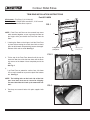
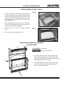
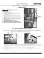
1
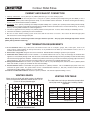
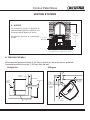
CONTOUR PELLET STOVE
INSTALLATION, OPERATION, AND MAINTENANCE INSTRUCTIONS
IMPORTANT! Record serial number of your stove on the warranty card and mail immediately.
The serial number is located on the safety label affixed behind the left side curtain on
the outside of hopper wall.
Please read this entire manual before installation and use of this pellet fuel room heater.
Failure to follow these instructions could result in property damage, bodily injury or even death.
1.
2.
3.
4.
5.
6.
7.
8.
9.
10.
11.
12.
13.
IMPORTANT SAFETY NOTES
When installing your stove, particular attention should be paid to fire protection. If this unit is not properly installed, a house
fire may result. For your safety, follow the installation instructions, and contact local building or fire officials about restrictions
and installation inspection required in your area.
Read power supply section of component information (page 15) before you plug in the stove.
Always unplug the stove before cleaning or servicing.
During operation, if any part of the stove starts to glow, the stove is in an overfired condition. Reduce the feed rate and increase
the amount of air going into the stove. OVERFIRING VOIDS WARRANTY.
Do not install a flue damper in the exhaust venting system of this unit.
Do not connect the stove to a chimney flue already serving another appliance.
Never use gasoline, gasoline-type lantern fuel, kerosene, charcoal lighter fluid, or similar liquids to start or freshen up a fire in
this heater. Keep all such liquids well away from the heater while it is in use.
The stove operates with a negative pressure firebox and a positive pressure exhaust. It is imperative that the chimney system
be airtight and installed correctly.
Dispose of all ashes in a metal container.
Comply with all minimum clearances to combustibles as shown on page 5.
The Quadra-Fire Contour is tested and approved for pelleted biomass fuel or shelled field corn only. Burning of any other
type of fuel voids your warranty!
Aladdin Hearth Products, manufacturer of the Contour pellet stove, reserves the right to alter its products, their specifications
and/or price without notice.
ALADDIN HEARTH PRODUCTS, GRANTS NO WARRANTY, IMPLIED OR STATED, FOR THE INSTALLATION OR
MAINTENANCE OF THIS UNIT AND ASSUMES NO RESPONSIBILITY FOR ANY CONSEQUENTIAL DAMAGE(S).
PRIOR TO FIRST FIRE: Remove all labels from glass. Clean gold surfaces with a glass cleanser and soft cloth
to prevent staining from fingerprint oils.
Tested and
Listed by
O-T L
Beaverton
Oregon USA
C
OMNI-Test Laboratories, Inc.
1445 N. Highway
Colville, WA 99114
SAVE THESE INSTRUCTIONS
250-5583
October 10, 2001
www.aladdinhearth.com
Contour Pellet Stove
Aladdin Hearth Products welcomes you to our tradition of excellence! In choosing a Quadra-Fire appliance, you have our
assurance of commitment to quality, durability, and performance.
This commitment begins with our research of the market, including ‘Voice of the Customer’ contacts, ensuring we make products
that will satisfy your needs. Our Research and Development facility then employs the world’s most advanced technology to achieve
the optimum operation of our stoves, inserts and fireplaces. And yet we are old-fashioned when it comes to craftsmanship.
During manufacturing each unit is meticulously fabricated and gold surfaces are hand-finished for lasting beauty and enjoyment.
Our pledge to quality is completed as each model undergoes a quality control inspection. Additionally, we feel it is important to
offer you several finishing options and accessories to compliment your home’s décor, individualize the use of your appliance,
and provide financial options in acquiring a quality hearth appliance. Ask your Quadra-Fire Dealer for information on these
options. From design, to fabrication, to shipping: Our guarantee of quality is more than a word, it’s Quadra-Fire tradition, and we
proudly back this tradition with a Lifetime Warranty.
Prior to installation, we ask you to take a few moments to read this manual. It has been our experience that your overall
enjoyment of your new appliance will be greatly enhanced by becoming familiar with its’ installation, operation and maintenance
requirements. We wish you and your family many years of enjoyment in the warmth and comfort of your hearth appliance.
Thank you for choosing Quadra-Fire.
With warm regards,
______________________
Group Vice President
______________________
Vice President
Research & Development
_____________________
Vice President
Marketing & Product Planning
_______________________
Controller
______________________
General Manager
______________________
Quality / Technical
Support Manager
_______________________
Manufacturing Engineer
Manager
_______________________
Central Sales Manager
______________________
Eastern Sales Manager
_______________________
Order Fulfillment Manager
_______________________
Sr. Purchasing Agent
______________________
Human Resources &
Community Relations
October 10, 2001
2
250-5583
Contour Pellet Stove
TABLE OF CONTENTS
MODEL NAME
Page
CONTOUR Pellet Stove
Safety Label......................................................... 4
Safety Label Location.............................................4
Clearances to Combustibles................................ 5
Floor Protection Requirements............................ 5
Serial Number
Listings and Specifications .................................. 5
Dimensions.......................................................... 5
Chimney and Exhaust Connections .................... 6
Date Purchased
Venting Termination Requirements...................... 6
Venting Graph and Pipe Table ............................. 6
Venting Systems
Dealership Where Purchased
A. Alcove...................................................... 7
B. Through the Wall...................................... 7
C. Vertical..................................................... 8
D. Through the Wall and Vertical .................. 8
E. Masonry................................................... 8
Dealer Phone
F. Alternate masonry.................................... 8
Top Vent Adapter ................................................. 9
Feed Adjustment Instructions .............................. 9
Additional Information:
Log Placement Instructions ................................. 10
Mobile Home Installation ..................................... 11
Thermostat Installation ........................................ 11
Operating Instructions ......................................... 11-12
Cleaning and Maintenance.................................. 13-14
Component Information ....................................... 15-17
Troubleshooting ................................................... 18-20
Wiring Harness.................................................... 20
Outside Air Kit Installation Instructions ................ 21
AFTER COMPLETING YOUR WARRANTY CARD, ATTACH
YOUR SALES RECEIPT AND WARRANTY STUB HERE
FOR FUTURE REFERENCE.
Trim Ring Installation Instructions........................ 22-23
Gold Grille Installation Instructions...................... 23
Exhaust Blower Replacement Instructions .......... 24
Feed Motor Replacement Instructions................. 24
Rear Screen Replacement Instructions............... 25
Top Baffle Removal Instructions .......................... 25
Accessories and Service Parts............................ 26
Warranty .............................................................. 27
Warranty card ......................................................Insert
October 10, 2001
3
250-5583
Contour Pellet Stove
SAFETY LABEL
LABEL LOCATION: BEHIND LEFT SIDE CURTAIN ON OUTSIDE OF HOPPER
Tested and
Listed by
O-T L
Serial No.
Model:
OMNI-Test Labs, Inc.
Beaverton, OR
Report No. 061-S-20-2
QUADRA-FIRE CONTOUR
Beaverton
Oregon USA
C
OMNI-Test Laboratories, Inc.
Room Heater Pellet Fuel BurningType
Also for use in Mobile Homes. This pellet burning appliance has been tested and listed
for use in Manufactured Homes in accordance with
OAR 814-23-900 through 814-23-909
1445 North Highway
Colville, WA 99114
'PREVENT HOUSE FIRES"
Install and use only in accordance with manufacturer's
installation and operating instructions. Contact Local
Building or Fire Officials About Restrictions and
Inspection in Your Area.
WARNING - FOR MANUFACTURED HOMES: Do not install
appliance in a sleeping room. An outside combustion air
inlet must be provided. The structural integrity of the
manufactured home floor, ceiling and walls must be
maintained.
Refer to manufacturer's instructions and local codes for
precautions required for passing chimney through a
combustible wall or ceiling. Inspect and clean exhaust
venting system frequently in accordance with
manufacturer's instructions.
Use a 3" or 4" diameter type "L" or "PL" venting system.
Do not connect this unit to a chimney flue servicing
another appliance.
Tested to:
ASTM E 1509, and ULC-C1482-M1990 Room Heater
Pellet Fuel Burning type (UM) 84-HUD
Input Rating Max 4 lb. fuel/hr.
Electrical Rating: 115 VAC, 60 Hz,
Start 4.1 Amps, Run 1.1 AMPS.
Route power cord away from unit
DANGER: Risk of electrical shock. Disconnect power
supply before servicing.
Replace glass only with 5mm ceramic available from
your dealer
To start, set thermostat above room temperature, the
stove will light automatically.
To shutdown, set
thermostat to below room temperature. For further
instruction refer to owner's manual.
Keep viewing and ash removal doors tightly closed
during operation.
FOR USE WITH PELLETIZED WOOD FUELOR SHELLED FIELD CORN ONLY.
Minimum Clearances to Combustible Materials
A
C
FLOOR PROTECTION
*H
B
G
C
D
F
G
I
E
G = 2"/5cm
H = 2"/5cm *See Exceptions Below
F
I = 6"/15cm
A Back Wall to Appliance
2"/5cm
B Side Wall to Appliance
6"/15cm
Corner Installation:
C Walls to Appliance
2"/5cm
Vertical 3" - 6" Adapter Kit (Part #812-3570) Installation:
D Back Wall to Appliance Flue
3"/8cm
E Side Wall to Appliance
6"/15cm
Corner Installation with Vertical Adapter Kit:
F Walls to Appliance
2"/5cm
Alcove Installation:
Min. Alcove Height:
43"/1092cm
Min. Alcove Side Wall
6"/15cm
Max. Alcove Depth
36"/91cm
Use a non-combustible floor protector extending under
unit and to the sides, front and back of unit as shown
in Floor Protection Diagram. Measure front distance
(I) from the surface of the glass door.
*Exceptions: Non-combustible floor protection must
extend beneath the fluepipe when installed with
horizontal venting or under the top vent adapter with
vertical installation.
Note 1: In residential installations, when using parts #811-0860, (3" - 3" Top Vent Adapter) and #812-3570 (3" - 6" Offset Adapter), 24
gauge 6" single wall flue connector may be used.
Note 2: In manufactured home installation, when using part #811-0860, (3" - 3" Top Vent Adapter) and #812-3570 (3' - 6" Offset
Adapter), use listed double wall flue connector. An Outside Air Kit (#811-0871), must be used with manufactured home installation.
U.S. ENVIRONMENTAL PROTECTION AGENCY
This model is exempt from EPA certification under 40 CFR 60.531 by definition [Wood Heater (A) "Air-to-Fuel Ratio"].
Date of Manufacture
2000 2001 2002 JAN FEB MAR APR MAY JUNE JULY AUG SEPT OCT NOV DEC
DO NOT REMOVE THIS LABEL
October 10, 2001
4
MADE IN U.S.A.
250-5583
Contour Pellet Stove
CLEARANCES TO COMBUSTIBLES
A
B
C
C
D
F
F
E
A Back Wall to Appliance 2"/5cm
B Side Wall to Appliance 6"/15cm
Corner Installation:
C Walls to Appliance
2"/5cm
Vertical 3" - 6" Adapter Kit (Part #812-3570) Installation:
D Back Wall to Appliance Flue
3"/8cm
E Side Wall to Appliance 6"/15cm
Corner Installation with Vertical Adapter Kit:
F Walls to Appliance
2"/5cm
Alcove Installation:
Min. Alcove Height:
43"/1092cm
Min. Alcove Side Wall
6"/15cm
Max. Alcove Depth
36"/91cm
Use a non-combustible floor protector extending under
unit and to the sides, front and back of unit as shown in
Floor Protection Diagram.
FLOOR PROTECTION
*H
G
G
I
Measure front distance (I) from the surface of the glass
G = 2"/5cm
door.
H = 2"/5cm
*See Exceptions*Exceptions: Non-combustible floor protection must
I = 6"/15cm
extend beneath the flue pipe when installed with
horizontal venting or under the Top Vent Adapter with
vertical installation.
LISTINGS AND SPECIFICATIONS
The QUADRA-FIRE CONTOUR pellet stove is safety listed
with OMNI-Test Labs, Inc., Beaverton, OR, to ASTM E
1509 and ULC-C1482-M1990 Room Heater Pellet Fuel
Burning type (UM) 84-HUD. Also suitable for use in mobile
homes. See pages 5 and 9 for mobile home installation
details.
HEAT OUTPUT*: 8,000 to 30,000 BTUs per hour
*BTU output will vary, depending on the brand of
fuel you use in your stove. Consult your Quadra-Fire
dealer for best results.
DIMENSIONS
25-7/16
4-1/8
10
12-23/32
30-5/8
31-1/2
17-1/16
21-7/16
17-15/16
October 10, 2001
5
250-5583
Contour Pellet Stove
CHIMNEY AND EXHAUST CONNECTION
1. Chimney & Connector: Use 3" (76mm) or 4" (102mm) diameter type "L" or "PL" venting system.
2. Mobile Home: Approved for all listed pellet vent. If using the 3" (76mm) vertical Top Vent Adapter Kit (part #811-0860), or the 3"
(76mm) to 6" (152mm) Offset Collar (part #812-3570), use listed double wall flue connector. An Outside Air Kit (part #811-0871),
must be used with manufactured home installation.
3. Residential: The 3" (76mm) vertical Top Vent Adapter Kit (#811-0860), and 3" (76mm) to 6" (152mm) Offset Collar (part #812-3570),
are tested to use 24 gauge single wall flue connector or listed double wall flue connector to Class A listed metal chimneys, or masonry
chimneys meeting ICBO standards for solid fuel appliances.
4. The stove is approved for all 3" (76mm) or 4" (102mm) diameter listed pellet vent. It can be either vertically or horizontally vented.
5. Install vent at clearances specified by the vent manufacturer.
6. Be sure to secure exhaust venting system to the stove with at least three set screws. Also secure all connector pipe joints
with at least three screws through each joint.
NOTE: All pipe must be sealed using welded seam pipe whenever possible. Seal pipe joints with high temperature silicone
(500°F [260°C] minimum rated only).
VENT TERMINATION REQUIREMENTS
1. Do not terminate vent in any enclosed or semi-enclosed area such as a carport, garage, attic, crawl space, under a sun
deck or porch, narrow walkway or closely fenced area, or any location that can build up a concentration of fumes such as a
stairwell, covered breezeway, etc.
2. Vent surfaces can get hot enough to cause burns if touched. Noncombustible shielding or guards may be required.
3. Termination must exhaust above air inlet elevation. It is recommended that at least 5' (1.5m) of vertical pipe be installed when
appliance is vented directly through a wall. This will create a natural draft, which will help prevent the possibility of smoke or odor venting
into the home during appliance shutdown. It will also keep exhaust from causing a nuisance or hazard by exposing people or shrubs to
high temperatures. The safest and preferred venting method is to extend the vent vertically through the roof.
4. Venting should terminate not less than 4' (1.2m) below, not less than 4' (1.2m) horizontally from, and not less than 1' (305mm) above
doors and windows, or gravity or ventilation air inlets into the building.
5. Distance between bottom of termination and grade should be 1' (305mm) minimum. This is conditional upon plants in the area,
and nature of grade surface. The grade surface must be a noncombustible material (i.e., rock, dirt). Distance between bottom of
termination and public walkway should be 7' (2.1m) minimum.
6. Distance to combustible materials should be 2' (51mm) minimum. This includes adjacent buildings, fences,
VENTING GRAPH
VENTING PIPE TABLE
EQUIVALENT PIPE LENGTH IN FEET
When running vertically with pellet venting, the following
chart can be used to determine whether to use 3" or 4"
(7.6cm or 10.2cm) diameter pipe
The table below can help you determine the equivalent
feet of pipe used for venting when installing a pellet
appliance.
30
4" (102mm) Diameter Pipe Only
Pellet Venting
Component
20
10
# of Elbows or Multiplied Equivalent
Feet of Pipe
By:
Feet
90° Elbow or Tee
x
5
45° Elbow
x
3
Horizontal Pipe
x
1
Vertical Pipe
x
.5
Component
Equivalent Feet
Total Equivalent Feet:
3" or 4" (76mm or 102mm) Diameter Pipe
0
1
2
3
4
5
6
7
8
9
10
ALTITUDE IN THOUSANDS OF FEET
October 10, 2001
6
250-5583
Contour Pellet Stove
VENTING SYSTEMS
A. ALCOVE
The Quadra-Fire Contour is approved for
minimum alcove height of 43” (109.2cm), and
a maximum alcove depth of 36” (91cm).
All minimums listed are to a combustible
surface.
43" (109.2cm)
Minimum
6" (15.2cm)
Minimum
Maximum Alcove Depth: 36"/91cm
B. THROUGH THE WALL
We recommend going a minimum 5' (15.25cm) vertical, but above the eave is preferred.
Horizontal termination must be 1' (30.5cm) from the wall.
Straight Out
45 Degree
2" (52mm)
Minimum
Wall
Thimble
Wall Thimble
Horizontal Cap
6" (152mm)
Minimum
From Glass
2" (51mm)
Minimum
Optional
Direction
12" (305mm)
Minimum
2" (51mm)
Minimum
Insulating Hearth Pad
October 10, 2001
7
250-5583
Contour Pellet Stove
VENTING SYSTEMS, CONT'D.
C. VERTICAL
D. THROUGH THE WALL & VERTICAL
Rain Cap
Rain Cap
Flashing
Flashing
24" (61cm) minimum
24" (610mm) minimum
Firestop
Class A Chimney
Connector Adapter
3" (7.6cm) Min.
Ceiling Support
Top Vent Kit
6" (15.2cm) Min.
Non-combustible Hearth Pad
Cleanout
Cover
2" (50mm) minimum
Wall Thimble
6" (152mm)
minimum
6" Flue Connector
(Single Wall for
residential installation.
Double Wall for mobile
home installation.)
OR
3" or 4" L Vent (For
residential or mobile
home installation.)
Support Bracket
(every 60" [152.4cm])
Tee
Cleanout Cover
Non-combustible Hearth Pad
E. MASONRY
F. ALTERNATE MASONRY
Concrete Cap
Concrete Cap
Fireclay flue
liner with airspace
Flashing
1" (25mm) clearance
with firestop
Fireclay Flue Liner
with airspace
Flashing
1" (25mm) clearance
with firestop
1" (25mm) clearance
3" (76mm) minimum
1" (25mm) clearance
2" (50mm) minimum
Sheathing
6" (152mm)
minimum
6" (152mm) minimum
Cleanout cover
Sheathing
Airtight
Cleanout Door
Airtight cleanout door
Non-combustible Hearth Pad
Non-combustible
Hearth Pad
October 10, 2001
8
250-5583
Contour Pellet Stove
TOP VENT FLUE ADAPTER INSTALLATION
Part #811-0860, 3"-3" Top Vent Adapter or Part #812-3570, 3"-6" Offset Collar
1)
2)
3)
4)
5)
6)
7)
8)
Put a layer of silicone on the 3" (76mm) exhaust
outlet.
Slide the flue adapter onto the rear exhaust outlet.
Adjust the assembly to a vertical position.
Drill four holes with #26 drill bit (provided) into the back
of the stove using the outer shield as a pattern (make
sure the assembly is vertical).
Install the four mounting screws.
Drill two holes with #26 drill bit through the Rear
Exhaust Outlet using the two holes already in the short
horizontal pipe in the Top Vent Adapter as a guide.
Install the two screws
Install the stove pipe into the adapter (be sure to
silicone all joints).
To clean adapter, remove cleanout cover.
Use hole on each
side as drilling guide
Rear Exhaust
Outlet
Mount with four
screws
FEED ADJUSTMENT
NOTES:
The feed adjustment rod is factory set, and should be
adequate for most fuels. However, if the flame height is too
high or too low, follow the instructions below.
Loosen the set screw (Fig. 1) 1/4 to 1/2 turn during set-up
of stove. This will allow movement of the Fuel Adjustment
Rod. Do not re-tighten set screw.
Cleanout Cover
1)
Loosen the wing nut.
2)
Adjust the fuel adjustment rod upward towards the "+"
symbol, to increase the feed rate and flame height,
or down towards the "-" symbol, to decrease the feed
rate and flame height.
3)
Re-tighten the wing nut.
Adjust fuel adjustment rod after the stove has been burning
for 10-15 minutes. The flames should be approximately
4"(102mm) above the firepot at high heat output setting.
FIGURE 2
FIGURE 1
Fuel Adjustment Rod
Wing Nut
October 10, 2001
9
250-5583
Contour Pellet Stove
LOG SET PLACEMENT INSTRUCTIONS
Part 811-0851 4 piece Log Set
Part 811-0900 Optional Firepot Twig
The logs are very fragile. You must use extreme
care when handling or cleaning the logs.
Step 1:
To expose the firebox open the door.
Fig. 1
4 PIECE LOG SET INSTALLATION
notch
Step 2: Position the Logs
Place the right rear log as shown. There is a notch in the
bottom of the log for clearance for the Thermocouple and
Thermocouple Cover (ceramic protection tube). Fig. 1
Thermocouple
cover
drop tube
Continue placing the last 3 logs around the firepot as
show in Fig. 2, 3 and 4. Be careful not to block the drop tube
in the back of the firebox where pellets feed into the firepot.
Fig. 2
OPTIONAL FIREPOT TWIG INSTALLATION
Step 3: Place the twig over the firepot. It will be about 2-1/2" above
the firepot when in place. Notice the position of the twig as
it rests on the 3 logs in a stable position to prevent it from
falling into the firepot. There is also a charred area on the
back of the twig, do not turn it toward the front. Fig. 5
Fig. 3
Fig. 5
Fig. 4
WARNING: Due to the abrasive nature of a pellet stove fire, the
logs are not covered under warranty. Any placement variation other
than shown here can cause excessive heat and shall void the stove
warranty.
October 10, 2001
10
250-5583
Contour Pellet Stove
MOBILE HOME INSTALLATION
1.
2.
3.
4.
5.
6.
7.
8.
9.
Do not install the stove in a sleeping room.
The structural integrity of the mobile home floor, walls
and ceiling/roof must be maintained (i.e., do not cut
through floor joists, wall studs, ceiling trusses, etc.).
An outside air inlet must be provided for the combustion
air and be unrestricted while the stove is in use. Use
Outside Air Kit (part #811-0871).
The combustion air duct system must be made of
metal. It must permit zero clearance to combustible
construction and prevent material from dropping into
the inlet or into the area beneath the dwelling and
contain a rodent screen.
The stove must be secured to the mobile home by
bolting it to the floor (using lag bolts).
The stove must be grounded with #8 copper grounding
wire or equivalent, terminated at each end with an NEC
approved grounding device.
Refer to Clearances to Combustibles Section on page
4 for listings to combustibles and appropriate chimney
systems.
Seal all wall and floor inlets to prevent air or moisture
penetration. Check periodically to ensure the inlet is
free of obstruction (e.g., snow, ice).
Installation should be in accordance with the Manufactured Home and Safety Standard (HUD), CFR 3280,
Part 24.
OPERATING INSTRUCTIONS
1. FUEL SIZE AND MATERIAL
Wood Pellets
Fuel pellets are made from sawdust or wood by-products.
If the source material is hardwood, they will have a higher
mineral content, creating a heavier ash. Minerals and
other noncombustible materials, such as sand, will turn
into glass when heated to the extreme temperatures our
firepot reaches. This is what forms clinkers in the bottom
of the firepot. Trees from different areas will vary in mineral
content. That is why some fuels produce more clinkers
than others. Pellets are manufactured in either 1/4” (6mm)
or 5/16” (8mm) diameter and many varying lengths. Pellet
lengths may even vary by lot from the same manufacturer
which is why the feed rate may need to be adjusted
occasionally. We recommend that you buy fuel in multiton lots whenever possible. Buying large quantities of
fuel at once will greatly reduce the number of times the
feed adjustments will need to be made. However, we
do recommend trying various brands before purchasing
multi-ton lots to ensure customer satisfaction.
Shelled Field Corn
Extensive factory and field testing has demonstrated
shelled field corn to be an efficient and very economical
fuel. We recommend the use of a 50-50 blend of corn
and wood pellets. The only change in operation is that
the feed rate may require a slight adjustment. The BTU
output of the appliance varies slightly compared to pellets,
depending on the quality of the corn used. In cases
where it is acceptable for the stove to run full time,
100% corn will work after the fire has been started using
wood pellets.
THERMOSTAT INSTALLATION
1.
2.
3.
A 24 volt AC thermostat is required to operate this
pellet stove and is included. It is equipped with an
adjustable heat anticipator. The current rating is .05
amps. The anticipator needs to be adjusted to the
2. BEFORE YOUR FIRST FIRE
lowest setting available.
a. First, make sure your stove has been properly installed
When mounting a thermostat on a wall, be sure to follow
and that all safety requirements have been met. Pay
your thermostat installation instructions carefully.
particular attention to the fire protection, venting and
thermostat installation instructions.
NOTE: Be sure the thermostat is mounted level for
b. Now open the front door of the stove and remove
accurate readings. The thermostat should be mounted
all of the accessories that were placed there for
on an inside wall and not in direct line with the stove
convection air.
shipment. Remove any labels that may be affixed
to the glass.
NOTE: If the thermostat is located too close to the
c. Check the position of the Thermocouple and make
stove, you may need to set the temperature setting
sure that it protrudes approximately 1” (2.5cm) into the
slightly higher to maintain the desired temperature in
firepot. It may be necessary to slide the Thermocouple
your home.
and Thermocouple Cover (ceramic protection tube)
into their proper positions. Now close the front door.
There is a four screw terminal block located on the back
NOTE: Thermocouple Cover tip must be touching
of the stove beside the power cord inlet. The center
the tip of the Thermocouple.
two screws are for the thermostat wires.
October 10, 2001
11
250-5583
Contour Pellet Stove
OPERATING INSTRUCTIONS
OPERATING INSTRUCTIONS
d. Check that all accessories have been removed before
filling the hopper with pellets and loosen set screw
located at the bottom of the hopper so that the feed rate
adjustment rod will slide up and down by only loosening
the wing nut at the top. See Figure 1, page 9.
e. A thermostat is required for proper operation of this
stove. At this time, set the thermostat to its lowest
setting.
3. START YOUR FIRST FIRE
a. Now plug the stove in. The combustion blower will come
on. Even though the thermostat is not calling for heat,
the combustion blower will stay on for approximately 10
minutes. This is normal.
b. Next, find the heat output control switch; it is mounted on
the back of the stove in the upper right hand corner. See
Fig. A. Switch it to the high setting by pushing the top
of the switch in, then adjust the thermostat to its highest
setting. With the right side panel opened, the red light
located to the left of the control box is now visible
and will be on. This will indicate that the thermostat
is calling for heat.
c. The fuel feed system and the igniter are now turned on.
d. For your first fire, it will be necessary to press the reset
button (located just beneath the heat output switch on
the back of the stove) once approximately two minutes
after start up, and again at five minutes. This will fill the
feed system and allow the stove to light.
e. The stove will now continue to run as long as the
thermostat is calling for heat. Once the stove has ignited,
let the stove burn for approximately 15 minutes, then set
the thermostat to the desired room temperature. Adjust
the heat output control to the desired setting
b. Once all of the start-up procedures have been
completed, simply set the thermostat to a comfortable
setting and enjoy the stove. But remember, you will
have to add pellets. The thermostat’s location will
have some effect on the stove’s operation. When
the thermostat is located close to the stove, it may
require a slightly higher temperature setting to keep
the rest of the house comfortable. If the thermostat
location is upstairs while the stove is downstairs, you
will notice higher temperatures near the stove.
c. During each ignition cycle, it is normal to see some
smoke. The smoke will stop once the fire starts.
d. After your stove has been burning for approximately
10 minutes, the convection blower will automatically
turn on. This blower transfers heat from your stove
into the room, and will continue to run after the
thermostat has stopped calling for heat until all of the
heat has been extracted from the stove.
e. Occasionally, the stove may run out of fuel and shut
itself down. If this happens, the red light will be on.
To restart the stove, fill the hopper and press the
reset button next to the heat output switch. (Refer to
item #5, and Fig. A for location.) When you press the
reset button the red light will go out, and when the
button is released the light will come back on. You
should see a fire in about four minutes. If not, press
the reset button again.
5. HEAT OUTPUT CONTROLS
Located on the right rear of stove is the Heat Output
Control Switch (rocker switch). See Fig. A below.
4. GENERAL OPERATION INFORMATION
a. Understand that the stove is like most modern furnaces
in that when the thermostat calls for heat, your stove
will automatically light and deliver heat in the most
efficient and economical way. When the room is up to
temperature and the thermostat is satisfied, the stove will
turn off. This stove is equipped with a heat output control
that has three settings or burn rates: low, medium and
high. Essentially the stove operates the same on all
three burn rates. The stove will turn on and off as the
thermostat demands. However, with the stove set on the
lower settings, the burn times will be longer.
October 10, 2001
12
Fig. A
250-5583
Contour Pellet Stove
CLEANING AND MAINTENANCE
NOTE: Unplug the stove before performing any
cleaning or maintenance
b. HOW OFTEN SHOULD YOU CLEAN THE
HEAT EXCHANGER?
The amount of ash buildup in the firepot will be a
good guide to determine how often you should
clean the heat exchangers. Typically, you should
clean the heat exchangers at least once a week.
This will keep your stove running at peak efficiency.
Also, after burning approximately one ton of fuel,
the ash will need to be removed from beneath
the heat exchangers.
1. FIREPOT
a. It takes very little time to clean the firepot. We
recommend that you clean the firepot daily.
However, if the fuel you are burning has a high dirt
content, it will be necessary to clean the firepot
more often. Dirty fuel will cause clinkers to form
in the firepot. A clinker is formed when dirt or
a nonburnable substance is heated to 2000°F
(1093°C) and becomes glass-like.
c. Remove Top Baffle. There is a latch to keep the
Top Baffle from coming out when cleaning the
Heat Exchangers. Push the latch up with your
finger while sliding the Top Baffle toward you, it
will then drop out. (Refer to Top Baffle Removal
Instructions, page 25, Figure 1 and 2). Remove
both cast firebrick panels. At the top of each
panel is a tab. First lift, then pull outward. With
baffle and panels removed from stove a thorough
cleaning can now be performed. Pull the Heat
Exchanger cleaning rods out and in to clean the
uppermost portion of the Heat Exchanger Tubes.
This area is only accessible when the baffle is
removed from the stove. Reinstall panels and
baffle and latch when finished cleaning.
b. To clean the firepot:
1. Wait for stove to be in complete shutdown
(exhaust blower off).
2. Pull firepot cleaning rod out, then push back
into the closed position. This can be done a
couple times to help shake debris loose.
3. Periodically the pedestal ash drawer will
need to be emptied. Lift the drawer handle
slightly and pull outward. Empty into a noncombustible container and reinstall ash drawer.
NOTE: NEVER pull rod when stove is operating.
2. FIREBOX ASH REMOVAL
a. Clean as needed due to ash buildup.
b. Allow stove to cool completely.
c. Ensure there are no hot ashes in the firebox prior
to cleaning.
d. Remove ash with an ash vacuum or small dust
pan and place ash in a metal or non-combustible
container.
NOTE: Embers remain hot for many days.
Store container in a safe place away from
combustibles.
4. VENTING SYSTEM
The venting system should be inspected and cleaned
at least once a year, or more often depending upon the
quality of your fuel. If you are experiencing nuisance
shutdowns, check for a clogged exhaust system. If the
exhaust is restricted, the vacuum safety switch will shut
the feed motor off (the red light will remain on).
5. DOOR LATCH ADJUSTMENT
To adjust, open the latch and pivot the holding rod out.
Now loosen the jam nut on the rod. With a Phillips
head screwdriver, turn the rod clockwise to tighten.
The latch handle should snap securely in place
when adjusted properly. After adjusting the latch,
be sure to tighten the jam nut on the rod to hold
the adjustment.
3. HEAT EXCHANGER MAINTENANCE AND
CLEANING
a. This stove has two heat exchange chambers. Each
chamber is equipped with its own cleaning rod. To
access the cleaning rods, open the front door. Both
pull rods are located next to the face of the stove.
To clean, pull the rod straight out approximately
10” (254mm). Move the rod in and out a couple
of times.
October 10, 2001
13
250-5583
Contour Pellet Stove
CLEANING AND MAINTENANCE CONT'D
6. BLOWERS
a. There are two blowers in this stove: an exhaust blower
that vacates the exhaust out of the firebox, and a
convection blower that delivers heat into the room.
THESE BLOWERS REQUIRE NO LUBRICATION.
b. The exhaust blower is located on the right side
of the stove. To inspect it, open the right side
access panel.
NOTE: The impeller on the motor can be cleaned
and inspected when performing heat exchanger
maintenance and cleaning.
c. The convection blower on the floor at the back of
the stove has two impellers, one on each side of
the motor. They should be cleaned at least once
each year. Brush and vacuum the impellers from
both sides.
7. READING THE FIRE AND ADJUSTMENT
PROCEDURES
A properly adjusted fire with the heat output control set
on high has a short active flame pattern that extends out
of the firepot approximately 4 inches (102mm). If the
fire has tall flames with black tails and seems somewhat
lazy, the feed rate will need to be reduced. This is done
by sliding the feed adjustment plate down, which will
reduce the feed. If the fire is not 4 inches (102mm), slide
feed plate up to increase the feed. Allow five minutes
for feed adjustment to take effect.
8. SOOT AND FLY ASH - FORMATION AND
NEED FOR REMOVAL
The products of combustion will contain small particles
of fly ash. The fly ash will collect in the exhaust venting
system and restrict the flow of the flue gases. Incomplete
combustion, such as occurs during start-up, shutdown,
or incorrect operation of the room heater will lead to
some soot formation, which will collect in the exhaust
venting system. The exhaust venting system should
be inspected at least once every year to determine if
cleaning is necessary.
October 10, 2001
14
250-5583
Contour Pellet Stove
COMPONENT INFORMATION
1. POWER SUPPLY
a. Check the wall receptacle for 120 volt, 60 Hz
(standard current). Make sure the outlet is
grounded and has the correct polarity.
2. FUSE
a. The fuse is on the front of the junction box, located
on the right side of the stove. To access fuse,
open the right side panel. To inspect the fuse,
push the fuse holder in and turn the holder cap
counterclockwise, then pull out. Replace with a
standard 7 amp 120 volt fuse, if necessary. If
the fuse continues to blow, contact your local
dealer.
3. RED CALL LIGHT
a. The red call light is located on the right side next
to the fuse. The function of the red call light is to
indicate that the thermostat is calling for heat.
b. If the thermostat is calling for heat, the stove is
burning, and the light is not on, check the bulb.
Replace with a 28 volt AC (#85 lamp) bulb.
4. RESET BUTTON
a. The reset button is located on the back of the
stove in the upper right hand corner just below
the heat output switch (see Fig. A on page 12).
The function of the button is to momentarily open
the thermostat circuit, which restarts the system.
However, this will only work when the thermostat is
calling for heat and the red light is on.
b. If the light is on, there is no fire, and there is
fuel in the firepot, push the reset button and wait
for ignition. You should have a fire within five
minutes.
c. If the light does not go out when the reset button
is pushed, the reset button switch may be faulty.
Contact your local dealer.
5. VACUUM SWITCH
a. The vacuum switch is located on the right side of
the stove. This switch turns the feed system on
when vacuum is present in the firebox. Check the
rubber hose for leaks or cracks if the feed system
fails to start. Also, be sure there is no restriction
in the exhaust system and the exhaust blower is
running. The vacuum switch is a safety device
to shut off the feed motor under the conditions
below.
October 10, 2001
b. If the exhaust or the heat exchanger system is dirty
or plugged, the vacuum switch will keep the feed
system from starting.
c. If the firebox door is open, the vacuum switch will
keep the feed system from starting.
6. JUNCTION BOX AND WIRING HARNESS
a. The junction box is located on the right side of the
stove. It contains the heat output controls, reset
button, call light and fuse holder.
b. The junction box and the wiring harness are
replaced as one component.
7. THERMOSTAT
a. The stove is designed to run on a 24 volt AC
thermostat.
NOTE: The heat anticipator should be set on
the lowest setting available. Also, check the
wire leads at the terminal block located at the
back of the stove for loose connections.
8. CONTROL BOX
a. The control box plugs into the side of the junction
box. It is secured by a retainer bracket for shipping
purposes only. To access the control box, simply
bend the retainer bracket out of the way.
Note: After 2 or 3 bends, the bracket will break
off. Discard the broken piece.
If the stove has just been plugged in and the
combustion blower does not start, check snap disc
#3, then check to make sure the stove is plugged
in. Next, check the control box to see that it is
securely plugged in. Also check the fuse to see that
it is not blown. If this does not solve the problem,
consult your local dealer.
NOTE: To see the temperature indicator lights,
the right side panel must be open.
b. The green light located on the top of the control
box notifies you that the stove has reached a
temperature of 200°F (93°C) in the firepot. After
the stove is lit, if this light does not light in the first
four minutes of operation, the stove will shut down.
Check the thermocouple.
c. The red light located in front of the green light is
to indicate that the stove has reached operating
15
250-5583
Contour Pellet Stove
COMPONENT INFORMATION, CONT'D.
for ten minutes, then turn off. After the stove
cools, the snap disc will automatically reset itself
and the stove will relight.
temperature. If this light does not come on in the
first nine minutes of start-up, the stove will shut
down. The stove will not try to relight again by
itself. You must manually push the reset button
to reset the cycle.
d. If you suspect a problem with the control box,
disconnect the power supply from the stove, then
remove the control box and take it to your nearest
Quadra-Fire dealer for testing.
NOTE: Do not open the control box. This
will void the warranty. Do not plug in or
remove control box without first unplugging
the stove.
12. SNAP DISC #3 (BACKBURN PROTECTOR) 250°F
a. Snap disc #3 is mounted on the back of the auger
tube in the center of the stove. To access it, open
the right side panel. If, for any reason, the fire
tries to burn back into the feed system or push
exhaust up the feed tube, this snap disc will shut
the entire system off. However, sometimes in
shipment the disc will trip and shut power off to
the entire stove. Power failures and surges can
also trip this disc. To reset, unplug the stove from
outlet and push in the red reset button in the
center of the snap disc, then plug the stove back
in and try to relight it.
9. THERMOCOUPLE
a. The thermocouple is located on top of the firepot
inside the ceramic protection tube. Remove the
ceramic tube and inspect the thermocouple for
deterioration or breakage.
b. Check the transition from thermocouple to wire to
see if they are tight and making a good electrical
connection (located on the right side of the fire box
behind the right side panel).
c. Upon reinstalling the ceramic cover, be sure the
thermocouple is touching the inside end of the
ceramic tube and that the cover is extending 1”
(25mm) into the firepot.
13. BLOWER #1 (EXHAUST BLOWER)
a. The 70 cfm exhaust blower is located on the right
side of the stove. The exhaust blower is designed
to pull the exhaust from the stove and push it out
through the venting system. To inspect it, open
the right side panel (facing the stove from the
front). The motor may now be visually inspected.
To inspect the impeller refer to the heat exchanger
maintenance cleaning section.
d. The thermocouple sends a millivolt signal to the
control box to obtain the green and red lights for
the preset temperatures.
14. BLOWER #2 (CONVECTION BLOWER)
a. The 160 cfm convection blower is mounted at the
rear of the stove. There are two impellers, one
on each side of the motor. The convection blower
blows heated air through the heat exchange
system into the room.
b. To replace this blower, remove the lower rear
screen then unplug the molex connector, lift on
the rear of the motor slightly, just enough so the
grommets on the rear will clear the two studs.
Pull straight out.
10. SNAP DISC #1 (CONVECTION BLOWER) 125°F
a. Snap disc #1 is located on the right side of the
stove, on the bottom of the heat exchanger box.
Two purple wires are connected to it. This snap
disc turns the convection blower (heated air) on
and off as needed. Power is always present at
snap disc #1.
11. SNAP DISC #2 (THERMOSTAT OVERRIDE)
200°F
a. Snap disc #2 is also located on the right side of
the stove, below snap disc #1. Two yellow wires
are connected to it. This snap disc will bypass the
thermostat and turn off the stove if an overheat
condition occurs, or if the convection blower
should fail to operate. The stove will go into a
normal shutdown: the combustion blower will run
October 10, 2001
15. FEED SYSTEM
a. The feed system is located on the right side of the
stove and can be removed as an entire assembly
which includes the feed motor, its mounting
bracket bearing, and feed spring (auger). To do
this, remove two Phillips head screws located next
to the nylon bearing and the whole feed system
will pull straight out. This system uses a hollow
16
250-5583
Contour Pellet Stove
COMPONENT INFORMATION (CONT'D.)
6. Reconnect the wire to the two leads in any order.
7. Reinstall the ceramic wire nuts by turning
clockwise.
8. Open right side panel and pull the wire leads back
toward the rear of the stove to take-up the four to
five inches pulled out previously. This will keep
the wires out of the way of the ash drawer.
9. Reinstall firepot guard and ash drawer and
reconnect the power.
auger spring to pull pellets up the feed tube from
the hopper area and drop them down the feed
chute into the firepot. If you are having fuel
problems, check the following:
1. Check the ramp in the firebox to see that it is
free of fuel or other materials.
2. Check the set screw on the end of the motor
shaft to see that it is tight and not slipping.
3. Check the electrical power to motor.
4. Check the vacuum switch hose connections.
16. IGNITER
NOTE: For your convenience, a spare ignitor has
been provided in the component package. It
is suggested that you keep a spare on hand.
Reorder from your dealer.
a. The igniter is mounted on the firepot. To inspect the
igniter, remove the ash drawer from the pedestal.
With this drawer removed, remove the firepot heat
shield. This is a flat plate mounted with two Phillips
head screws. You can now inspect both the igniter
and firepot, and have gained access for removal or
replacement of either part.
b. Check the wire leads to the igniter for loose or bad
connections (ceramic wire nuts).
NOTE: Unplug stove before checking wire nuts.
INSTRUCTIONS FOR CHANGING THE IGNITER
1. UNPLUG THE STOVE.
2. Remove the bottom ash drawer. Use a Phillips
head screwdriver and remove the two screws that
secure the firepot guard. The guard is located just
beneath the ash catcher in front of the firepot.
With the guard removed, the ignition chamber
on the firepot and the wiring is now exposed.
The wires are connected together with two
ceramic wire nuts. These wires will pull forward
approximately four to five inches.
3. Holding the wires, turn the wire nut counterclockwise to remove the wire nuts.
4. With nuts removed and wires separated, remove
the igniter from the chamber: use a Phillips
screwdriver to remove the single screw and slide
the igniter out.
5. Install new igniter into the chamber.
October 10, 2001
17. FIREPOT
a. Clean the firepot (see section on Cleaning and
Maintenance on page 13).
b. When inspecting the firepot, make sure that the
firepot floor is closing completely. Then see that
the bottom floor is closing with no visible gaps, and
is free of any ash or debris.
18. DOOR GASKET
a. To inspect the door gasket, open the door and see
that the door rope extends approximately 1/8" to
3/16" from the door rope channel. It should show
signs of compaction all the way around the door
where the rope contacts the face of the stove.
19. HEAT EXCHANGERS
a. The heat exchangers (one on each side) can be
accessed by removing the top stainless steel baffle.
Each heat exchanger has a cleanout rod located
in the center of the heat exchanger. To clean
heat exchanger see page 13, Heat Exchanger
Maintenance and Cleaning.
17
250-5583
Contour Pellet Stove
TROUBLESHOOTING
CAUTION: UNPLUG STOVE BEFORE SERVICING
NOTE: If the lights fail to come on after
the fire starts, the thermocouple may
be faulty.
d. If the thermocouple appears good, the control
box may be the problem (consult your dealer).
1. PLUG IN STOVE, NO RESPONSE
a. Check the power supply for 120 volts AC.
b. Check the fuse in the junction box (7 amp, 120
volt fuse AGC-7).
c. Check snap disc #3 (unplug stove before
checking). Push reset on snap disc #3.
d. Control box (consult your dealer).
4. CALL LIGHT ON, NO FIRE, UNBURNED PELLETS
IN FIREPOT
a. Clean the firepot.
b. Push the reset button.
c. Check the igniter to see that it comes on (see
a glow in the firepot). If it does not turn on,
check the following:
1. Check the connections under the firepot.
(Ceramic wire nuts must be used to
withstand the heat produced by the firepot.)
2. Make sure that the igniter is property installed
in the igniter bracket.
2. CALL LIGHT ON, NO FIRE, NO FUEL IN
FIREPOT
a. Check the hopper for fuel, sawdust or bridging
of pellets in the bottom of the hopper. If the hopper
is low on fuel, vacuum can be lost through the
hopper.
NOTE: Sometimes there might still be fuel in
the hopper. If so, continue to check the areas
below.
b. Make sure that the exhaust blower is operating.
c. Check the venting system for obstructions that
might cause restrictions, which would cause the
vacuum safety switch to shut off the auger.
d. Check the heat exchanger system for high
ash content. If buildup is present, clean the heat
exchanger system.
e. Push the reset button and try, to light the stove
again.
5. SLOW OR SMOKY START-UP
a. Clean the firepot.
b. Check the combustion blower (make sure
that it is starting when the thermostat calls
for heat).
c. Visually check the cleanliness of the firebox, the
heat exchangers and the venting system.
d. The feed rate may be too high. If necessary,
adjust with the fuel adjustment rod located
in the hopper.
3. CALL LIGHT ON, NO FIRE, PARTIALLYBURNED FUEL IN THE FIREPOT
a. Clean the firepot.
b. Check the hopper for fuel or bridging problems,
as the firepot may not have received enough
fuel to start.
c. Inspect the thermocouple and cover for the
following:
1. The cover needs to be making contact
with the end of the thermocouple.
2. The thermocouple and the cover should
extend approximately 1” (25mm) into the
firepot (for accurate temperature reading).
3. Push the reset button. When the
thermocouple reaches 200°F (93°C) the
GREEN LIGHT will come on, and at 600°F
(316°C) the RED LIGHT will come on.
October 10, 2001
6. STOVE RUNS FOR 10 MINUTES, THEN STOPS
FEEDING FUEL
a. Inspect the thermocouple and the cover.
1. The cover needs to make contact with the
end of the thermocouple.
2. The thermocouple and the cover should
extend approximately 1” (25mm) into the
firepot.
3. Push the reset button. The thermocouple
test lights located on the control box
will automatically turn on; when the
thermocouple reaches 200°F (93°C) the
GREEN LIGHT comes on, and at 600°F
18
250-5583
Contour Pellet Stove
TROUBLESHOOTING (CONT'D.)
(316°C) the RED LIGHT comes on. If
they fail to turn on after the fire starts, the
thermocouple may need replacement.
4. Check the control box (consult dealer).
7. FEED SYSTEM FAILS TO START
a. Make sure that the front door to the firebox
is closed tightly.
b. Check to make sure that the exhaust blower is
coming on and working.
c. Adjust heat output control to high.
d. Check the heat exchangers and the venting
system for obstructions or heavy ash buildup.
e. The vacuum switch hose may be plugged.
NOTE: Unplug stove from power outlet first.
Pull the hose off and blow through it to make
sure it is clear.
f. Downdrafts or poor venting systems that do not
follow manufacturers recommendations can
also cause this problem.
g. Check the hopper and the feed system for
blockage.
8. THERMOSTAT WILL NOT START UNIT
a. Check the power to the stove.
1. Unplug for 10 seconds and then plug in.
The exhaust blower should come on. If it
does, go to 8b. If not, see Troubleshooting
item #1.
b. The thermostat or the thermostat wiring may
be faulty.
1. Disconnect the thermostat wires from the
terminal block located on the back of the
stove. Make a jumper wire in order to create
a manual bypass to determine if the stove
or the thermostat is faulty.
NOTE: Unplug the stove while hooking
up the jumper wire. Plug the stove back
in and the unit should come back on
and light. If the unit lights, check the
thermostat and the wires connecting
them.
October 10, 2001
c. Snap disc #2 would bypass the thermostat if
an overheat situation occurs. The snap disc
should reset itself once it cools down.
d. Snap disc #3 may need to be manually reset if
the unit has overheated.
e. Check the control box (consult dealer).
9. UNIT FAILS TO SHUT OFF
a. Check the thermostat and the thermostat
wires.
1. Remove one of the thermostat wires from
the terminal block; the stove should go
into a normal shutdown cycle. If it does,
the problem is in the thermostat or the
thermostat wiring.
b. Check the control box (consult dealer).
c. Check the junction box (consult dealer).
10.
SMOKE FROM THE CONVECTION AIR
OUTLET
a. Check the exhaust blower housing and ALL
venting connections.
b. Most problems with smoke in the house are
the result of a poor venting system or unsealed
joints.
11. CONVECTION BLOWER KEEPS RUNNING OR
FAILS TO START
a. Snap disc #1 may need to be replaced.
b. Check the wire connections on snap disc #1 and
the convection fan to be sure a good contact
is being made.
c. Check the convection blower.
12. STOVE CYCLES ON AND OFF, THERMOSTAT
ALWAYS ON
a. Check that snap disc #1 is coming on and
turning the convection blower on. If not, snap
disc #2 could be bypassing the thermostat until
the snap disc cools and resets itself.
19
250-5583
Contour Pellet Stove
TROUBLESHOOTING (CONT'D)
13. LARGE FIRE, ASH BUILDUP AND DIRTY
GLASS
a. Clean the firepot.
b. Visually check the cleanliness of the firebox, the
heat exchangers and venting system.
c. Reduce the feed rate, if necessary.
14. UNIT BURNING, NO CALL LIGHT
a. Replace light bulb (#85 lamp).
WIRING HARNESS
T-STAT CONN
T-STAT CONN
YELLOW w/WH
4
5
6
1
2
3
BURN RATE
SNAP DISC #2
SNAP DISC #2
(YEL)
SNAP DISC #3
(GRAY)
BLUE
YELLOW
w/WH
P.B.
GRAY
SNAP DISC #1
LIGHT
ORANGE
(PUR)
(PUR)
(BLK)
NEUTRAL CONV.
(WHT)
NEUTRAL COMB.
(WHT)
NEUTRAL IGN.
(HT)
IGNITER
(HT)
BLACK
ORANGE
Green w/pink spade
YELLOW
(WHT)
PURPLE
NEUTRAL AUGER
GRAY
(WHT)
BLUE
NEUTRAL IN
HI-TEMP
COMB. BLOWER (BLU) SWITCH
HI-TEMP
BLK
RED
VAC.
M
RED
(RED)
NEUTRAL
AUGER MOTOR
BLUE
(RED/WHT)
RED
YELLOW
K
BLK
WHITE
BL
AUGER MOTOR
AUG.
CAP.
YELLOW
RE
D
WHITE
M
(PUR)
CONV. BLOWER
YELLOW w/WH
BLK
M
FUSE
GRAY
15 14 13 12 11 10 9 8 7 6 5 4 3 2 1
To .250 Q.D.'s for Thermocouple
October 10, 2001
20
250-5583
Contour Pellet Stove
Outside Air Kit Instructions
Part #811-0871
Parts Included in Kit: 1 piece of 2"x3' flex hose, 2 hose clamps, 1 collar assembly, 1 termination cap assembly,
1 trim ring, 12 screws (Discard air channel).
Tools Needed: Phillips Screwdriver; Wire Cutters; Hole Saw or Jig Saw.
The Contour Pellet Stove has 2 different mounting configurations on the back of the stove for installing the
Outside Air Kit. Identify which type you have and follow the appropriate instructions.
PRE-CUT HOLE in back of stove (Fig. 2), attach the Collar Assembly to outside of stove as shown in (Fig 3).
SQUARE COVER PLATE, (Fig 4) attach Collar Assembly inside stove as shown in (Fig 5).
Instructions:
1. Open left side panel to access the inside rear area of stove (Square Cover Plate only). Attach Collar Assembly.
See Fig. 5
2. Measure distance from floor to air vent opening in stove and mark location on wall.
Use saw to cut opening in wall. Cut a 2-1/2" to 3" opening on inside wall and a 3" to 3-1/2"
opening on outside of house.
3. Use hose clamp to secure flex pipe to Collar Assembly.
Termination Cap with
4. Slide trim ring over flex pipe and run pipe through wall.
Rodent Screen
5. Attach hose to outside termination cap with second hose clamp.
6. Secure termination cap to outside surface.
Hose Clamp
7. Secure trim ring to interior wall.
Fig. 2
Fig. 3
Trim Ring
Fig. 1
Flex Hose
Fig. 4
Fig. 5
Hose Clamp
Collar Assembly
Attach Collar
Assembly over
hole.
Snip corners and remove plate.
October 10, 2001
21
250-5583
Contour Pellet Stove
TRIM RING INSTALLATION INSTRUCTIONS
Part #811-0820
Kit Contents: Trim Ring (1); 8-32 Nuts (6)
Grille
Tools Required: Phillips head screwdriver; 11/32" wrench
or nut driver; small screwdriver or punch.
FIG. 1
Rib
NOTE: Front Face and Door can be removed from stove
while attached together, or you may leave the Door on
the hinges while you remove the Front Face from the
Door.
1
Face
Rib
If leaving the Door on the hinges, hold the Front Face
in place while removing the screws from Grille so that it
does not fall forward and potentially become damaged.
Remove Grille and set aside. See Fig. 1
Locating Screws
(on rib, the two
Locating Screws
(on rib, the two
Door
FIG. 2
2. Tilt the top of the Front Face forward until the top rib
clears the door, then slide the face down until the locating screws on the bottom rib are completely out of the
door.
See Fig. 2
3.
Lay Front Face on protective surface, face side down
Use a small screwdriver or punch to push filler buttons
out. See Fig. 3
NOTE: The holding tabs on the back side of the buttons have been bent over to secure for shipping.
You must bend the tabs back up to remove the buttons.
4
FIG. 3
Touch-up area around holes with paint supplied with
stove.
October 10, 2001
22
250-5583
Contour Pellet Stove
TRIM RING INSTRUCTIONS, CONT'D
FIG. 4
6. Turn the Front Face over so it is face side up. Beginning
with one straight side of trim ring first, place the studs
on the trim ring into the holes on the Front Face. After
the first two studs have dropped into their holes, carefully lay the trim ring down until all of the studs are in
place. See Fig. 4.
7. While holding the trim ring in place, turn the Front Face
over and lay on protective surface to prevent the trim
ring from getting scratched. See Fig. 5
8. Place nuts on all six studs, and gently snug them
down.
FIG. 5
9. To re-assemble, simply reverse steps 1-3.
Gold Grille Installation Instructions
Part #811-0830
Grille
KIT CONTENTS: (1) Gold Grille
TOOLS NEEDED: Phillips head screwdriver.
Rib
1. The screws secure the Front Face and Grille to the
Door. When removing the two screws, hold the Door
and Front Face together so that neither will fall causing
potential damage. Save the screws.
Face
2.
Install new gold Grille using screws removed in Step
One. Ensure that screws are inserted through the
Grille, Front Face Rib and Door.
Door
October 10, 2001
23
250-5583
Contour Pellet Stove
Exhaust Blower Replacement Instructions
Part #812-4400
Included in Kit: (1) Blower; (1) Gasket
Tools Required: Phillips Screwdriver; Flathead
Screwdriver or 1/4" Nutdriver.
FIG.1
FIG. 2
CONTOUR SHOWN
WITH TOP REAR
SCREEN AND
VACUUM SWITCH
REMOVED.
Exhaust
Blower
Remove
wires from
Blower
Lower Rear Screen
1. Unplug stove.
2. Remove both side curtains by opening halfway, then
lifting up and pulling back.
3. Disconnect vacuum hose and both wires (orange and
red) from the vacuum switch so you can remove the top
rear screen.
4. Unscrew and remove top rear screen.
5. Unscrew lower rear screen, and lay it on it's back as
shown in Fig. 1.
6. Remove both wires from exhaust blower (blue and
double white).
7. Remove 6 screws using a flathead screwdriver or a
1/4" nutdriver. Retain screws for use on replacement
blower. See Fig 2.
8. Remove exhaust blower and gasket.
9. Install new gasket and blower by reversing steps 1-8.
FEED MOTOR Replacement Instructions
Part #812-4420
Feed motor
FIG. 2
FIG. 1
mounting
Molex Connectors
Auger shaft
set screw
Feed Motor Mount Screws
Rectangular
nylon bearing
1. UNPLUG THE STOVE.
2. Open the right Side Curtain to expose the Feed Motor.
3. Disconnect the Molex connectors. Remove the two
screws from the Feed Motor Mount. (Figure 1)
4. Pull the Feed Motor/Auger assembly straight out towards
you, being careful not to hit the Control Box.
October 10, 2001
5. Loosen set screw that secures Auger Shaft to Feed Motor
Shaft. (See Figure 2), Remove 4 screws attaching Feed
Motor to mount. Lift off old motor and replace with new.
Secure with screws. Ensure Auger Shaft set screw aligns
with flat side of Feed Motor Shaft.
6. Re-assemble in reverse order.
24
250-5583
Contour Pellet Stove
Rear Screen Replacement Kit Instructions
Part #812-4510
Included in Kit: 1 Rear Replacement Screen
Tools Required: Phillips screwdriver
1. Lift off both side curtains.
2. Unscrew lower screw ONLY on each side curtain
mounting bracket.
3. Detach vacuum switch from rear screen (2 screws).
4. Remove and retain the 10 screws from the existing
rear screen and remove screen from stove. Discard old
screen.
5. Attach new screen to rear of stove using 10 screws
removed in step 4.
6. Re-attach vacuum switch to rear screen.
7. Re-attach lower screw to side mounting brackets.
8. Attach side curtains and align if necessary by adjusting
lower screw on side mounting brackets.
Vacuum
Switch
Mounting
Bracket
Lower mounting
bracket screw
TOP BAFFLE REMOVAL INSTRUCTIONS
Your new Contour stove has a latch to keep the top baffle from coming out during shipment or when
the heat exchanger scraper rods are pulled.
Latch
Second
Notch
Face of Stove
Latch
FIGURE 2.
FIGURE 1.
Second Notch
Top Baffle
1) To remove the top baffle for periodic thorough cleaning of the heat exchanger, first locate the latch. It is located
between the front edge of the top baffle and the inside of the firebox centered from side to side. The latch pivots
up and down.
2) Push the latch up with your finger while sliding the top baffle forward and down. See FIGURE 1
3) To reinstall the top baffle, align the hooks on the baffle with the slots in the baffle hangers, push up and slide back.
See FIGURE 2.
4) Make sure the latch drops back into position, bypassing the first notch and catching the front edge of the top baffle
with the second small notch.
October 10, 2001
25
250-5583
Contour Pellet Stove
ACCESSORIES
811-0820
811-0830
811-0851
811-0900
811-0871
811-0840
811-0860
812-3570
812-3760
811-0520
Gold Face Trim 24K
Gold Grille, 24K
Log Set, 4 piece
Log, Twig (to cover firepot)
Outside Air Kit
Pedestal Base, Cast Iron
Top Flue Adapter, 3” to 3”
Top Flue Offset Collar, 3” to 6”
Thermostat, Mechanical
Thermostat, Programmable
SERVICE PARTS
812-4460
80791
80793
80792
812-4540
812-4400
812-0760
812-0750
812-0730
812-4410
832-1680
812-4420
812-3530
812-4430
812-0380
812-3780
812-4440
200-2720
812-3500
812-4460
80796
812-3811
812-4450
812-1560
812-3420
812-0340
812-1322
812-4470
812-3430
842-2240
October 10, 2001
Baffle, Stainless Steel
Brick, Cast, Left Side
Brick, Cast, Right Side
Brick, Cast, Center
Blower, Convection
Blower, Exhaust
Call Light, Bulb
Call Light, Lens
Ceramic Wire Nut
Control Box
Door Rope
Feed Motor
Firebox Draw Latch
Firepot, EZ Clean
Fuse, .7 amp
Fuse, .8 amp
Glass, Door
Glass, Warming Shelf
Heat Output Control Switch (Rocker Switch)
Heat Exchanger Cover
Hopper Lid Hinge, Cast
Igniter, Loop
Junction Box/Wiring Harness
Snap Disc #1 (125 Degree, Convection Fan)
Snap Disc #2 (200 Degree, High Limit)
Snap Disc #3 (250 Degree, High Limit)
Thermocouple Cover (ceramic protection tube)
Thermocouple
Vacuum Switch
Warming Shelf Door Latch
26
250-5583
Contour Pellet Stove
Lifetime Warranty
LIMITED LIFETIME WARRANTY
The Aladdin Hearth Products limited Lifetime Warranty guarantees that the following components will work as designed for the
lifetime of the stove or Aladdin Hearth Products will repair or replace them. These items include but are not limited to steel and
cast iron components, all gas burners, gas logs, combustion chambers, heat exchanger systems, stainless steel firebox
components, gold plating, doors, glass damaged by thermal breakage, steel baffle supports, steel and ceramic baffles and
manifold tubes. Labor is for the first five years.
THREE YEAR WARRANTY
Our EZ Clean firepots are covered under Aladdin Hearth Products three-year warranty program. Labor is for 3 years.
TWO YEAR WARRANTY
All electrical components such as but not limited to blowers, wiring, vacuum switches, speed controls, control boxes, thermodisc
switches, pilot assembly, gas valves, thermostats and remotes are covered under Aladdin Hearth Products two-year warranty
program. The igniter is not covered by any warranty, expressed or implied.
ONE YEAR WARRANTY
Porcelain finishes are warranted against manufacturer defects for one year. Labor to repair or replace these parts is covered for
one year, reimbursed per our warranty service fee schedule.
CONDITIONS
This warranty is non-transferable and is made to the original retail purchaser only provided that the purchase was made through
an authorized dealer of Aladdin Hearth Products. It must be installed and operated at all times in accordance with the Installation
and Operating Instructions furnished with this product, as well as any applicable local and national codes. Any alteration, willful
abuse, accident, or misuse of the product shall nullify this warranty.
Labor to repair or replace items covered under the limited Lifetime Warranty will be covered for the first five years per our
warranty service fee reimbursement schedule. Parts covered under the limited Lifetime Warranty will be covered for the lifetime
of the appliance up to a maximum of ten (10) years after Aladdin Hearth Products discontinues the model. Adjustments, regular
maintenance, cleaning and temporary repairs do not qualify for a service call fee and will not be covered. The replacement of
consumer replaceable items and installation of upgraded component parts do not quality for a service call fee, and will not be
covered.
This limited Lifetime Warranty does not extend to or include surface finish on the appliance, logs for oil or pellet stoves, door
gasketing, glass gasketing, thermocouple covers, firebrick, kaowool or other ceramic insulating materials. It does not cover
installation or operational-related problems such as overfiring, use of corrosive driftwood, downdrafts or spillage caused by
environmental conditions, nearby trees, buildings, hilltops, mountains, inadequate venting or ventilation, excessive offsets, or
negative air pressures caused by mechanical systems such as furnaces, fans, clothes dryers, etc.
Any installation, construction, transportation, or other related costs or expenses arising from defective part(s), repair,
replacement, etc., will not be covered by this warranty, nor will Aladdin Hearth Products assume responsibility for them. Further,
Aladdin Hearth Products will not be responsible for any incidental, indirect, or consequential damages, except as results in
damage to the interior or exterior of the building in which this appliance is installed. This limited Lifetime Warranty does not
apply to the venting components, hearth components or other accessories used in conjunction with the installation of this
product not manufactured by Aladdin Hearth Products.
This warranty is void if the stove has been overfired or operated in atmospheres contaminated by chlorine, fluorine, or other
damaging chemicals, the stove is subjected to prolonged periods of dampness or condensation, or there is any damage to the
stove or other components due to water or weather damage which is the result of, but not limited to, improper chimney or
venting installation. Aladdin Hearth Products may, at its discretion, fully discharge all obligations with respect to this war ranty by
either repairing or replacing the unit, or refunding the wholesale price of the defective part(s).
This limited Lifetime Warranty is effective on all Quadra-Fire appliances sold after May 1, 2002 and supersedes any and all
warranties currently in existence.
REV C
October 10, 2001
27
250-5583
ATTENTION INSTALLER:
PLEASE RETURN THESE
OPERATING AND INSTALLATION
INSTRUCTIONS TO CONSUMER
A Division of Hearth Technologies Inc.