1
Acer Altos R520 Series
User’s Guide
Copyright © 2006 Acer Incorporated
All Rights Reserved.
Acer Altos R520 Series
User’s Guide
Changes may be made periodically to the information in this publication without obligation
to notify any person of such revision or changes. Such changes will be incorporated in new
editions of this manual or supplementary documents and publications. This company makes
no representations or warranties, either expressed or implied, with respect to the contents
hereof and specifically disclaims the implied warranties of merchantability or fitness for a
particular purpose.
Record the model number, serial number, purchase date, and place of purchase information in
the space provided below. The serial number and model number are recorded on the label
affixed to your server. All correspondence concerning your unit should include the serial
number, model number, and purchase information.
No part of this publication may be reproduced, stored in a retrieval system, or transmitted, in
any form or by any means, electronic, mechanical, photocopy, recording, or otherwise,
without the prior written permission of Acer Incorporated.
Acer Altos R520
Model Name :
Part Number:
Purchase Date:
Place of Purchase:
Acer and the Acer logo are registered trademarks of Acer Inc. Other company’s product
names or trademarks are used herein for identification purposes only and belong to their
respective companies.
iii
Notices
FCC notice
Class A equipment
This device has been tested and found to comply with the limits for a Class A
digital device pursuant to Part 15 of the FCC Rules. These limits are designed to
provide reasonable protection against harmful interference when the
equipment is operated in a commercial environment. This equipment
generates, uses, and can radiate radio frequency energy, and if not installed
and used in accordance with the instructions, may cause harmful interference to
radio communications. Operation of this equipment in a residential area is
likely to cause harmful interference, in which case the user will be required to
correct the interference at personal expense.
However, there is no guarantee that interference will not occur in a particular
installation. If this device does cause harmful interference to radio or television
reception, which can be determined by turning the device off and on, the user
is encouraged to try to correct the interference by one or more of the following
measures:
•
Reorient or relocate the receiving antenna
•
Increase the separation between the device and receiver
•
Connect the device into an outlet on a circuit different from that to which
the receiver is connected
•
Consult the dealer or an experienced radio/television technician for help
Notice: Shielded cables
All connections to other computing devices must be made using shielded cables
to maintain compliance with FCC regulations.
Notice: Peripheral devices
Only peripherals (input/output devices, terminals, printers, etc.) certified to
comply with the Class A limits may be attached to this equipment. Operation
with noncertified peripherals is likely to result in interference to radio and TV
reception.
iv
Caution! Changes or modifications not expressly approved by the
manufacturer could void the user’s authority, which is granted by
the Federal Communications Commission, to operate this server.
Use conditions
This part complies with Part 15 of the FCC Rules. Operation is subject to the
following two conditions: (1) this device may not cause harmful interference,
and (2) this device must accept any interference received, including interference
that may cause undesired operation.
Notice Canadian users
This device does not exceed the Class A limits for radio noise emissions from
digital apparatus set out in the interference-causing equipment standard
entitled “Digital Apparatus” ICES-003 of the Canadian Deparmment of
Communications.
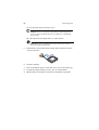
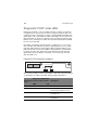
Laser compliance statement
The DVD-ROM drive in this server is a laser product. The optical drive’s
classification label (shown below) is located on the drive.
CLASS 1 LASER PRODUCT
CAUTION: INVISIBLE LASER RADIATION WHEN OPEN. AVOID EXPOSURE TO
BEAM.
v
Important safety instructions
Read these instructions carefully. Save these instructions for future reference.
1
Follow all warnings and instructions marked on the product.
2
Unplug this product from the wall outlet before cleaning. Do not use
liquid cleaners or aerosol cleaners. Use a damp cloth for cleaning.
3
Do not use this product near water.
4
Do not place this product on an unstable cart, stand, or table. The product
may fall, causing serious damage to the product.
5
Slots and openings on the back or bottom side of the chassis are provided
for ventilation; to ensure reliable operation of the product and to protect
it from overheating, these openings must not be blocked or covered. The
openings should never be blocked by placing the product on a bed, sofa,
rug, or other similar surface. This product should never be placed near or
over a radiator or heat register, or in a built-in installation unless proper
ventilation is provided.
6
This product should be operated from the type of power indicated on the
marking label. If you are not sure of the type of power available, consult
your dealer or local power company.
7
Do not allow anything to rest on the power cord. Do not locate this
product where persons will walk on the cord.
8
If an extension cord is used with this product, make sure that the total
ampere rating of the equipment plugged into the extension cord does not
exceed the extension cord ampere rating. Also, make sure that the total
rating of all products plugged into the wall outlet does not exceed the fuse
rating.
9
Never push objects of any kind into this product through the chassis slots as
they may touch dangerous voltage points or short out parts that could
result in a fire or electric shock. Never spill liquid of any kind on the
product.
10
Do not attempt to service this product yourself, as opening or removing
covers may expose you to dangerous voltage points or other risks. Refer all
servicing to qualified service personnel.
11
Unplug this product from the wall outlet and refer servicing to qualified
service personnel under the following conditions:
a
When the power cord or plug is damaged or frayed
b
If liquid has been spilled on the product
c
If the product has been exposed to rain or water
vi
d
If the product does not operate normally when the operating
instructions are followed. Adjust only those controls that are covered
by the operating instructions since improper adjustment of other
controls may result in damage and will often require extensive work
by a qualified technician to restore the product to normal condition.
e
If the product has been dropped or the chassis has been damaged
f
If the product exhibits a distinct change in performance, indicating a
need for service.
12
Replace the battery with the same type as the product's battery we
recommend. Use of another battery type may present a risk of fire or
explosion. Refer battery replacement to a qualified service technician.
13
Warning! Batteries may explode if not handled properly. Do not
disassemble or dispose of them in fire. Keep them away from children and
dispose of used batteries promptly.
14
This product is not suitable for use with visual display workplace devices
according to §2 of the German Ordinance for Work with Visual Display
Units.
iii
iii
iv
v
1 System tour
1
System features
Performance
External and internal structure
Front bezel
Front panel
Rear panel
Internal components
System boards
Mainboard
Backplane board
Mid-plane board
Control panel
System LED indicators
Control panel LED indicators
Hot-plug HDD LED indicators
System jumpers
2 System setup
Setting up the system
Pre-installation requirements
Connecting peripherals
Turning on the system
Power-on problems
Configuring the system OS
Turning off the system
3 System upgrade
Installation precautions
ESD precautions
Pre-installation instructions
Post-installation instructions
Opening the server
Removing and installing the front bezel
Removing and installing the top cover
Removing and installing the CPU air duct
3
3
7
7
8
9
10
11
11
13
15
17
20
24
25
27
29
31
31
32
33
34
35
36
37
39
39
39
40
41
41
43
45
Contents
Notices
FCC notice
Laser compliance statement
Important safety instructions
viii
Removing the CPU air dam
Removing and installing the power
distribution board cover
Configuring the storage devices
Removing and installing a hard disk drive
Removing and installing a slim-line optical drive
Removing and installing a PCI riser assembly
Removing and installing a PCI card
Upgrading the CPU
CPU upgrading guidelines
Upgrading the system memory
Memory module installation guidelines
Memory module population guidelines
Memory configuration overview
Installing and removing a power supply module
Removing and installing an ARMC/3 module
Installing and removing the SAS hardware
RAID components
Installing and removing the RAID activation
key and RAID cache
Installing and removing the RAID BBU
Installing and removing the SATA software RAID
activation key
47
48
50
50
53
56
58
61
61
67
68
68
70
76
79
82
82
84
87
4 BIOS setup
89
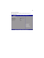
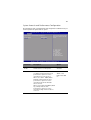
BIOS setup
Entering BIOS setup
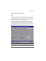
Using the BIOS menus
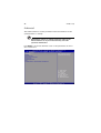
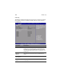
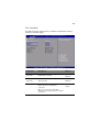
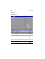
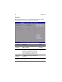
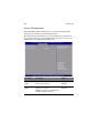
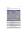
Main
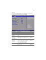
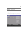
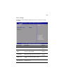
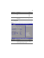
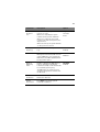
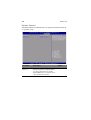
Advanced
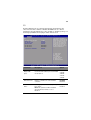
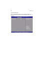
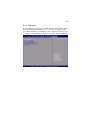
Security
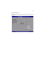
Server Management
Boot Options
Boot Manager
Error Manager
Exit
Upgrading the BIOS
91
92
94
94
96
112
114
118
121
122
123
125
5 Troubleshooting
Troubleshooting
Resetting the system
Problems following initial system installation
First steps checklist
127
129
129
129
130
ix
Hardware diagnostic testing
Verifying proper operation of key system lights
Specific problems and corrective actions
Error beep codes
BIOS POST error beep codes
ARMC/3 module error beep codes
Diagnostic POST code LEDs
131
131
132
139
139
141
142
Appendix A: Acer Altos R520
rack installation guide
149
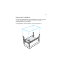
Setting up the system rack
System rack installation
Vertical mounting hole pattern
Installing the system into the rack
151
153
154
155
Appendix B: RAID configuration
Configuring integrated SAS RAID
Configuring the integrated SAS SW RAID
Configuring the onboard SATA RAID
163
165
167
169
174
x
1 System tour
The Acer Altos R520 is a 1U dual-core Intel Xeonbased server equipped with numerous high
performance features designed to provide easy
server set up, remote management, highly
reliable shared storage, and handle more
demanding database or high transaction
applications.
This chapter provides a brief overview of the
system hardware, including illustrations with
component identification.
3
System features
Listed below are the key features of the Acer Altos R520 server.
Performance
Processor
•
Supports two dual-core or quad-core Intel® Xeon™ processors
5000 sequence with 667 MHz, 1066 MHz, or 1333 MHz front side
bus speed
•
Extended Memory 64-bit Technology
•
Enhanced Intel SpeedStep Technology
•
Execute Disable Bit Technology
Chipset
•
Intel 5000P Memory Controller Hub (north bridge)
•
Intel ESB2-E (Enterprise South Bridge) I/O Controller (south bridge)
Memory
•
Quad memory channels
•
Eight DDR2 FBDIMM (fully buffered DIMM) slots
•
Supports 512 MB, 1 GB, and 2 GB DDR2 667 MHz FBDIMM
•
Support for the following RASUM (reliability, availability,
serviceability, usability, and manageability) features:
•
Memory error detection and correction
•
Memory scrubbing
•
Retry on correctable errors
•
Memory built-in self test
•
Memory sparing
•
Memory mirroring
Media storage
•
Slim-line IDE optical drive
•
Supports either a SAS or SATA HDD interface
4
1 System tour
•
For SATA models, the embedded SATA controller support
- Passive mid-plane board
- Six onboard SATA connectors
- Up to six hot-plug 2.5” SATA hard disk drives
- Intel Embedded Server RAID Technology capable of SATA
software RAID levels:
•
•
RAID 0
•
RAID 10
•
RAID 1
•
RAID 5 (optional)
For SAS models, the embedded SAS controller support
- Active mid-plane board
- Up to eight hot-plug 2.5” SAS hard disk drives
- Intel Embedded Server RAID Technology capable of SAS
software RAID levels:
•
RAID 0
•
RAID 1
•
RAID 10
- Provides optional hardware RAID support through
installation of a RAID activation key and a RAID cache on
the mid-plane board. The SAS hardware RAID levels
supported include:
•
RAID 0
•
RAID 61
•
RAID 1
•
RAID 10
•
RAID 5
•
RAID 50
Note: The active mid-plane board provides a 244-pin mini-DIMM
connector, supporting a single registered ECC non-parity DDR2400 MHz mini-DIMM to provide RAID cache. To protect from data
loss in the RAID cache in the event of power failure, you can also
install a RAID BBU.
1 Supported when available.
5
Networking
•
Intel ESB2 I/O controller
•
Intel 82563EB Gigabit controller with dual ports
•
Supports Intel I/O Acceleration Technology
PCI I/O
•
Low profile riser slot
•
•
One x8 PCI Express slot
Full height riser slot
•
One x8 PCI Express slot
•
One 64-bits/133 MHz PCI-X slot (optional)
Graphic interface
•
ATI® ES1000 video controller with 16MB DDR SDRAM
Server management
•
•
BMC (Baseboard Management Controller)
•
IPMI (Intelligent Platform Management Interface) 2.0
compliant
•
In-band and out-band server management
ARMC/3 (Acer Remote Management Card/3) module (optional)
•
High performance KVM redirection
•
Includes a dedicated NIC port
•
USB mouse, keyboard, and media redirection
Control panel
•
Mini control panel
•
Full-function control panel (optional)
I/O ports
•
Front
•
USB 2.0 port
•
VGA/monitor port (optional)
6
•
1 System tour
Rear
•
PS/2 keyboard port
•
PS/2 mouse port
•
Serial B port (RJ-45)
•
Two Gigabit (10/100/1000 Mbps) LAN ports (RJ-45)
•
Server management port (10/100 Mbps) (RJ-45)2
•
VGA/monitor port
•
Two USB 2.0 ports
Operating system and software
•
Operating system options
•
Microsoft® Windows® Server 2003, x64 edition
•
Microsoft Windows Server 2003
•
Novell Netware 6.5
•
Red Hat Enterprise Linux 4.0
•
Red Hat Enterprise Linux 4.0, EM64T
•
SUSE® Linux Enterprise Server 9.0
•
SUSE Linux Enterprise Server 9.0, EM64T
•
ASM (Acer Server Manager) 3
•
Easy Build 2
Power supply
•
Supports one to two 650-watts power supply modules
•
Supports redundant (1+1) or non-redundant (1+0) power
configuration
System fan
•
Five dual rotor system fans
2 Reserved for remote management of server. This requires installation of an
ARMC/3 module to mainboard.
3 For more information on how to install and use ASM and Easy Build utilities,
refer to the manual on the EasyBUILD DVD.
7
External and internal structure
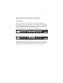
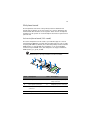
Front bezel
The front bezel provides an interface for system management via
status LED indicators. The light pipes on the backside of the front bezel
allow the system status LEDs to be monitored when the front bezel is
closed. Separate front bezels are available to support systems that use
a mini control panel or full-function control panel.
Front bezel supporting mini control panel
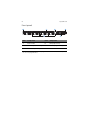
Front bezel supporting full-function control panel (optional)
The front bezel is removable to allow access to the server’s hard drives,
peripheral device, and control panel. For details on how to remove the
front bezel, see “To remove the front bezel” section on page 41.
8
1 System tour
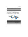
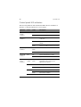
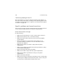
Front panel
Item
Component
Item
Component
A
Rack handles
D
Dual-purpose bay*
B
Slim-line optical drive bay
E
2.5” hot-plug HDD bays
C
Mini control panel bay
* The Acer Altos R520 dual-purpose bay supports either the full-function control panel or
two 2.5” hot-plug HDD drives.
9
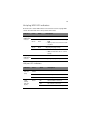
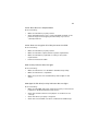
Rear panel
Item
Component
Item
Component
A
PS2 mouse port
G, H
USB 2.0 ports
B
Low profile PCI expansion
slot
I
VGA/monitor port
C
Full height PCI expansion slot
J, K
Gigabit LAN ports (10/100/
1000 Mbps)
D
Power supply module1
L
DB9 serial port A
E
Power supply module bay
filler panel
M
PS2 keyboard port
F
Server management port (10/
100 Mbps) (RJ-45) cover 2
1 The system power can be configured to support redundant (1+1) and non-redundant (1+0)
configuration.
2 Reserved for remote management of server. This requires the installation of an ARMC/3
module.
10
1 System tour
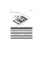
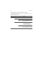
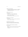
Internal components
Item
Component
Item
Component
A
Power distribution board
G
Memory modules
B
Power distribution board
cover
H
CPU air duct
C
Power supply module 1
I
System fan modules
D
Power supply module bay 2
(filler panel shown)
J
Mid-plane board (active
mid-plane shown)
E
Riser card assembly
K
Bridge board
F
Mainboard
11
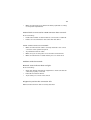
System boards
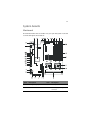
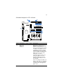
Mainboard
The mainboard becomes accessible once you open the system. It should
look like the figure shown below.
Item
Description
Item
Description
A
Rolling BIOS jumper
W
Battery
B
Intel ESB2-E I/O controller
X
Power supply management
connector
12
1 System tour
Item
Description
Item
Description
C
Diagnostic POST code
indicators
Y
Dual port USB 2.0 connector
D
Full height PCI riser slot
Z
SATA 0 connector
E
Low profile PCI riser slot
AA
SATA 1 connector
F
USB ports
BB
SATA 2 connector
G
VGA/Monitor port
CC
SATA 3 connector
H
System ID indicator
DD
SATA 4 connector
I
System status indicator
EE
SATA 5 connector
J
Gigabit LAN1 and LAN 2
ports
FF
SATA software RAID
activation key connector
K
Serial B port
GG
ARMC/3 module connector
L
PS2 mouse (top) and
keyboard (bottom) port
HH
System recovery settings
jumper block
M
Serial B configuration
jumper
II
Serial A connector
N
FBDIMM slots
JJ
NIC module connector
O
Intel 5000P MCH
P
CPU socket 1
Q
CPU socket 2
R
CPU voltage regulator
S
Bridge board connector
T
IDE optical drive connector
U
CPU power connector
V
AC power connector
13
Backplane board
SAS/SATA backplane board
The backplane board installed on the rear side of the hot-plug drive
bay provides support for both SAS and SATA hard drives.
Front view
Item
Description
Item
Description
A
Slim-line optical drive connector
C
SAS/SATA connectors
B
Mini control panel connector
14
1 System tour
Rear view
Item
Description
Item
Description
A
Control panel connector
D
Mid-plane connectors
B
USB connector
E
Backplane power connector
C
IDE connector
15
Mid-plane board
The mid-plane boad serves as the primary interface between the
mainboard, backplane, and control panel. It is used to determine the
desired hard drive interface for the system. There are two mid-planes
available for this system: an active mid-plane board and a passive midplane board.
Active mid-plane board (SAS model)
The active mid-plane board is used to provide SAS support. It has an
integrated LSI 1068 SAS controller that provides support for up to eight
hot-plug SAS HDDs. By default, the active mid-plane provides software
RAID levels 0, 1, and 10. With the installation of an optional RAID
activation key and RAID cache, the mid-plane can support hardware
RAID levels 0, 1, 5, 6, 10, and 50.
Note: Mid-plane will support RAID level 6 when available.
B
C
A
D
E
F
K
J
I
G
H
TP
Item
Description
Item
Description
A
Fan 2 power connector
G
RAID BBU (battery backup
unit) connector
B
Fan 1 power connector
H
Mid-plane power connector
C
RAID activation key
connector
I
Thumbscrew
D
Bridge board connector
J
Fan 4 power connector
16
1 System tour
Item
Description
Item
Description
E
Fan 6 power connector
K
Fan 3 power connector
F
RAID cache slot
Passive mid-plane board (SATA model)
The passive mid-plane board is used to provide SATA support for the
onboard SATA controller and six SATA ports. The mid-plane also
supports up to six hot-plug SATA HDDs and software RAID levels 0, 1,
and 10. With the installation of an optional SATA software RAID
activation key can support software RAID level 5.
Item
Description
Item
Description
A
Fan 2 power connector
F
Fan 6 power connector
B
Fan 1 power connector
G
HBA I2C connector
C
Thumbscrew
H
Fan 4 power connector
D
Bridge board connector
I
Fan 3 power connector
E
Mid-plane power connector
17
Control panel
The Acer Altos R520 server supports either the mini control panel,
providing basic functionality, or the full-function control panel, which
adds additional server management features. Both control panels
utilize a combination of control buttons, status LED indicators, along
with I/O ports, to centralize system control, monitoring, and
accessibility.
Mini control panel
A
B
C
G
F
D
E
TP02215
Item
Component
Item
Component
A
USB 2.0 port
E
Power/sleep button
B
System identification
indicator
F
NMI button
C
System status indicator
G
System ID button
D
Power/sleep indicator
18
1 System tour
Full-function control panel (optional)
AB C D E F
G
H
I
L
K
J
TP02213
Item
Component
Item
Component
A
LAN 2 activity indicator
G
System ID indicator
B
LAN 1 activity indicator
H
System ID button
C
Power/sleep button
I
Reset button
D
Power/sleep indicator
J
USB 2.0 port
E
HDD actvity indicator
K
NMI button
F
System status indicator
L
VGA/monitor port
19
Control panel button function overview
The following table list and describe the function of the control
buttons available on the control panel.
Control button
Function
NMI button
Puts the server in a halt-state for diagnostic purposes
and allows you to issue a non-maskable interrupt.
After using the interrupt, a memory download can be
performed to determine the cause of the problem.
Reset button
Reboots and initializes the system.
Power/sleep button
Toggles the system power on and off. This button also
functions as a sleep button if enabled by an ACPIcompliant operating system.
System ID button
Toggles the front panel ID LED and the mainboard
system ID LED on and off. The mainboard system ID
LED is visible through the rear of the chassis and
allows you to locate the server you’re working on
from behind a rack of servers.
20
1 System tour
System LED indicators
This section describes the different LED indicators located on
•
Mainboard
•
Control panel
•
Hot-plug HDD carrier
•
LAN port
•
Hot-plug power supply module
21
Mainboard diagnostic LED indicators
Item
Description
A
Diagnostic
POST code
indicators
Color
State
Description
During the system boot process,
BIOS executes a number of
platform configuration processes,
each of which is assigned a specific
hex POST code number. As each
configuration routine is started,
BIOS will display the given POST
code to the POST Code Diagnostic
LEDs found on the rear of the
mainboard. To assist in
troubleshooting a system hang
during the POST process, the
diagnostic LEDs can be used to
identify the last POST process to
be executed.
Refer to the Diagnostic POST code
table on page 142. for a complete
description of how these LEDs are
read, and a list of all supported
POST codes.
22
1 System tour
Item
Description
Color
State
Description
B
System ID
indicator
Blue
On
The system ID buton on the control
panel is activated
Off
System identification is disabled
Blink
Appropriate hex IPMI “Chassis
Identify” value has been issued
Green/
Amber
Altern
ating
blink
Pre DC power on - 30-35 second
BMC initialization when AC power
is applied to the system
Green
On
System booted and ready or
normal operation
Blink
System degraded
• Unable to use all of the
installed memory
C
System
status
indicator
• System loses memory
redundancy when memory
mirroring takes place
• System loses memory
redundancy when memory
sparing takes place
• Redundancy loss such as power
supply or fan
• PCI-E link error
• CPU failure or disabled
• Fan alarm or failure
• Non-critical temperature and
voltage threshold crossed
23
Item
Description
Color
State
Description
System
status
indicator
(cont.)
Amber
On
Critical or non-recoverable
condition
• DIMM failure when there is one
DIMM present
• Run-time memory
uncorrectable error in
non-redundant mode
• IERR signal asserted
• Processor 1 missing
• Critical temperature
• Power fault
• CPU configuration error
Blink
Non-critical condition
• Critical voltage threshold
crossed
• VRD hot asserted
• Fans failed or not present
• Correctable error threshold in
non-sparing and non-mirroring
mode crossed
Off
AC power off
D
DIMM error
indicators
On
System BIOS disables a DIMM after
it reaches a specified number of
given failures or critical DIMM
failures are detected
E, F
CPU error
indicator
On
• CPU is disabled
• CPU configuration error is
detected
G
5-volt
standby
present
indicator
On
• AC power is applied to the
system
• 5 V standby voltage is supplied
to the system by the power
supply
24
1 System tour
Control panel LED indicators
The following table list and describe the LED indicators available on
the mini or optional full-function control panel.
Indicator
Color
State
Description
LAN1/LAN2
activity
indicator
Green
On
Link between system and network
Blink
Network access
Off
System is not powered on or ACPI S4
or S5 state
On
System has power applied to it or ACPI
S0 state
Blink
System is in ACPI S1 state (sleep mode)
Random
blink
HDD is active
Off
No HDD activity
On
System identification is active
Off
System identification is disabled
Green/
Amber
Alternating
blink
Pre DC power on - 30-35 second BMC
initialization when AC power is
applied to the system
Green
On
Running or normal operation
Blink
System degraded
On
Critical or non-recoverable condition
Blink
Non-critical condition
Power/Sleep Green
indicator
HDD activity
indicator
System ID
indicator
System
status
indicator
Green
Blue
Amber
Off
POST or system stop
25
Hot-plug HDD LED indicators
There are two status LED indicators mounted for each hot-plug HDD
carrier. The table below list the possible drive states.
Indicator
Color
State
Description
Hot-plug
HDD activity
indicator
Amber
Flash
HDD is active
Amber +
Green
Alternate
flash
• HDD is powered on and rebuilding
RAID
• HDD is powered on and is in a fault
condition
Green
Blink
Off
Ongoing hot-plug activity
• No HDD is installed
• HDD is initiated but has no current
activity
Hot-plug
HDD failure
indicator
Amber
On
HDD failure.
Green
Blink
Ongoing hot-plug activity
LAN port LED indicators
Indicator
Color
State
Description
Speed
indicator
(left)
Green/
Amber
Off
10 Mbps connection
Green
On
100 Mbps connection
Amber
On
1000 Mbps connection
Green
On
Network link is detected
Off
No network connection
Blink
Transmit or receive activity
Link/
activity
indicator
(right)
26
1 System tour
Hot-plug power supply module LED indicator
The table below list and describe the bi-color LED indicator located on
the power supply module.
Indicator
Color
Status
Off
Green
Amber
State
Description
No AC power to the power supply
On
System has power applied to it
Blink
AC power cord is plugged into an
active AC power source
On
• No AC power
• Power supply critical event
(i.e, failure, fuse blown, fan
failed, etc.) causing shutdown
Blink
Power supply displays warning
event (i.e., high temperature, high
power, high current, slow fan, etc.)
27
System jumpers
Jumper name
Settings
Function
J1D2
1-2 (default)
Password enabled
Password clear
2-3
Password disabled/cleared
J1D3
1-2 (default)
BIOS clear CMOS
Clear CMOS
2-3
Forced CMOS clear
J3H1
BIOS select
1-2
2-3 (default)
Force lower bank
Normal operation
J1D1
BMC force update mode
1-2 (default)
2-3
BMC force update disabled
BMC force update enabled
J8A3
1-2
DCD (Data Carrier Detect) to DTR
(Data Terminal Ready) signal
3-4 (default)
DSR (Data Set Ready) to DTR signal
Serial B port (RJ-45)
28
1 System tour
2 System setup
This chapter gives you instructions on how to set up
the system. Procedures on how to connect
peripherals are also explained.
31
Setting up the system
Pre-installation requirements
Selecting a site
Before unpacking and installing the system, select a suitable site for
the system for maximum efficiency. Consider the following factors
when choosing a site for the system:
•
Near a grounded power outlet
•
Clean and dust-free
•
Stable surface free from vibration
•
Well-ventilated and away from sources of heat
•
Secluded from electromagnetic fields produced by electrical
devices such as air conditioners, radio and TV transmitters, etc.
Checking the package contents
Check the following items from the package:
•
Acer Altos R520 server system
•
Acer EasyBUILDTM
•
Acer Altos R520 accessory box
If any of the above items are damaged or missing, contact your dealer
immediately.
Save the boxes and packing materials for future use.
32
2 System setup
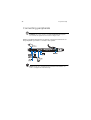
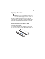
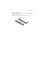
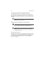
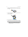
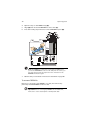
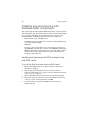
Connecting peripherals
Caution! The server operates on 100-127/200-240 VAC only. Do
not connect the system to an incorrect voltage source.
Refer to the illustration below for specific connection instructions on
the peripherals you want to connect to the system.
Note: Consult the operating system manual for information on
how to configure the network setup.
33
Turning on the system
After making sure that you have properly set up the system and
connected all the required cables, you can now power on the system.
Note: After plugging in the AC power cord, allow system to warm
up for 30 seconds or until the status/fault indicator on the control
panel stops blinking before turning on the system.
Refer to “Control panel” on page 17 for the location of the status/
fault indicator. The location of the status/fault indicator will
depend on the type of control panel installed on your system.
To power on the system:
1
Remove the front bezel. See “To remove the front bezel”section
on page 41.
2
Press the power button on the control panel.
The system starts up and displays a welcome message on the monitor.
After that, a series of POST messages appears.
Note: If the system does not turn on or boot after pressing the
power button, go to the next section for the possible causes of the
boot failure.
If the POST finds any problems, the system will emit a beep code
followed by an error message displayed on the monitor. Aside from the
POST messages, you can determine if the system is in good condition
by checking if the following occurred:
•
Power indicator on the control panel lights up (green)
•
Num Lock, Caps Lock, and Scroll Lock indicators on the keyboard
light up
34
2 System setup
Power-on problems
If the system does not boot after you have applied power, check the
following factors that might have caused the boot failure.
•
The external power cord may be loosely connected.
Check the power cord connection from the power source to the
power supply module AC input connector on the rear panel. Make
sure that the power cord is properly connected to the power
source and to the AC input connector.
•
No power comes from the grounded power outlet.
Have an electrician check your power outlet.
•
Loose or improperly connected internal power cables.
Check the internal cable connections. If you are not confident to
perform this step, ask a qualified technician to assist you.
Warning! Make sure all power cords are disconnected from
the electrical outlet before performing this task.
Note: If you have gone through the preceding actions and the
system still fails to boot, ask your dealer or a qualified technician
for assistance.
35
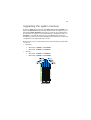
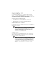
Configuring the system OS
The Acer Altos R520 server comes with Acer EasyBUILDTM that allows
you to conveniently install your choice of operating system. To start
using EasyBUILD, follow the steps below.
1
Locate the EasyBUILD DVD included in the system package.
2
With the system turned on, gently press the optical drive’s Stop/
Eject button.
3
When the disc tray slides open, insert the EasyBUILD DVD with the
label or title side of the disc facing upward.
Note: When handling the disc, hold it by the edges to avoid
smudges or fingerprints.
4
Gently press the disc down to make sure that it is properly
inserted.
Caution! While pressing the disc, be careful not to bend the disc
tray. Make sure that the disc is properly inserted before closing
the disc tray. Improper insertion may damage both the disc and
the CD-ROM drive.
5
Gently press the drive Stop/Eject button again to close the disc
tray.
6
The Acer EasyBUILD sequence begins. Follow all onscreen
instructions.
For more information, refer to the EasyBUILD Installation guide.
Note: EasyBUILD DVD supports Windows Server 2003, Red Hat
Linux, and SUSE operating system only.
Windows or Linux OS CD is needed when you install the OS with
the EasyBUILD DVD.
36
2 System setup
Turning off the system
There are two ways to turn off the server. These include:
•
Software power off
If you are using a Windows OS on your server, you can turn off the
server by clicking the Start button, point to Shut Down..., select
Shut down from the drop-down window then click on OK. You
can then turn off all peripherals connected to your server.
If you are using another OS, refer to the OS documentation for
instructions on how to shut down the OS.
•
Hardware power off
If you cannot shut down the server using the software, press the
power button for at least four seconds. Quickly pressing the
button may put the server in a Suspend mode only.
3 System upgrade
This chapter discusses the precautionary measures
and installation procedures you need to know to
upgrade the system.
39
Installation precautions
Before you install any server component, we recommend that you read
the following sections. These sections contain important ESD
precautions along with pre-installation and post-installation
instructions.
ESD precautions
Electrostatic discharge (ESD) can damage the processor, disk drives,
expansion boards, motherboard, memory modules and other server
components. Always observe the following precautions before you
install a server component:
1
Do not remove a component from its protective packaging until
you are ready to install it.
2
Wear a wrist grounding strap and attach it to a metal part of the
server before handling components. If a wrist strap is not
available, maintain contact with the server throughout any
procedure requiring ESD protection.
Pre-installation instructions
Perform the steps below before you open the server or before your
remove or replace any component:
1
Turn off the system and all the peripherals connected to it.
2
Unplug all cables from the power outlets.
3
Place the system unit on a flat, stable surface.
4
Open the system according to the instructions on page 41.
5
Follow the ESD precautions described in this section when
handling a server component.
6
Remove any hardware structure or cable that block access to the
component you must replace or upgrade.
See the following sections for specific installation instructions on the
component you want to install.
40
3 System upgrade
Warning! Failure to properly turn off the server before you
start installing components may cause serious damage. Do
not attempt the procedures described in the following
sections unless you are a qualified service technician.
Post-installation instructions
Perform the steps below after installing a server component.
1
See to it that all components are installed according to the
described step-by-step instructions.
2
Reinstall all components or cable that have been previously
removed.
3
Reinstall the top cover.
4
Reinstall the front bezel.
5
Connect the necessary cables.
6
Turn on the system.
41
Opening the server
Caution! Before you proceed, make sure that you have turned
off the system and all peripherals connected to it. Read the “Preinstallation instructions” on page 39.
You need to open the server before you can install additional
components. The front bezel and top cover are removable to allow
access to the system’s internal components. Refer to the following
sections for instructions.
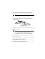
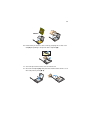
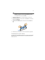
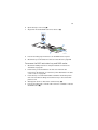
Removing and installing the front bezel
To remove the front bezel:
1
If necessary, remove any cables attached to the control panel.
2
Grasp the front bezel at the outer edge and pull it straight out.
42
3 System upgrade
To install the front bezel:
1
Line up the center notch on both ends of the bezel with the center
guide on the rack handles.
2
Slide the front bezel onto the chassis until it clicks into place.
43
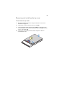
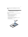
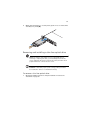
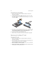
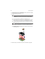
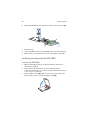
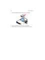
Removing and installing the top cover
To remove the top cover:
1
Observe the ESD precautions and pre-installation instructions
described on page 39.
2
Remove the screw located on the top cover (A).
3
Press and hold the blue release button (B), then slide the cover
toward the back of the chassis until the cover disengage with the
slots on the chassis (C).
4
Lift the top cover away from the server and put it aside for
reinstallation later.
44
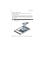
3 System upgrade
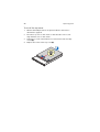
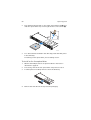
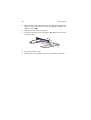
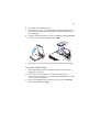
To install the top cover:
1
Observe the ESD precautions and pre-installation instructions
described on page 39.
2
Place the top cover on the chassis so that the tabs on the cover
align with the slots on the chassis .
3
Slide the top cover toward the front of the chassis until it is fully
closed (A).
4
Replace the screw on the top cover (B).
45
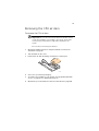
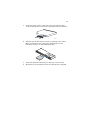
Removing and installing the CPU air
duct
Caution! Always operate your server with the CPU air duct
installed to ensure reliable and continued operation.
To remove the CPU air duct:
You will need to remove the CPU air duct to perform the following
procedures:
•
Removing and installing a CPU air baffle
•
Removing and installing the PCI riser assembly
•
Removing and installing the PCI card
•
Removing and installing a CPU
•
Removing and installing a memory module
1
Observe the ESD precautions and pre-installation instructions
described on page 39.
2
Lift the CPU air duct from the chassis.
46
3 System upgrade
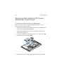
To install the CPU air duct:
1
Observe the ESD precautions and pre-installation instructions
described on page 39.
2
Place the CPU air duct over the two processor sockets. The front
edge of the air duct should touch the front fan module and the
top of the installed air duct should be flush with the top of the PCI
riser assembly.
Caution! Do not pinch or unplug cables that may be near or
under the air duct.
3
Observe the post-installation instructions described on page 40.
47
Removing the CPU air dam
To remove the CPU air dam:
Important: Do not remove the CPU air dam from the CPU air duct
except when installing a second CPU to the system. The air dam
ensures proper air flow when a single CPU is installed to the
system.
Do not remove the memory air deflector.
1
Observe the ESD precautions and pre-installation instructions
described on page 39.
2
Turn the CPU air duct over.
3
Remove the air dam by sliding slotted holes off duct pins.
TP02227
4
Store it in a protective packaging.
5
To install a second CPU to your system, see “Upgrading the CPU”
section on page 61 for detailed instructions.
6
Observe the post-installation instructions described on page 40.
48
3 System upgrade
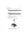
Removing and installing the power
distribution board cover
To remove the power distribution board cover:
You will need to remove the power distribution board cover to
perform the following procedures:
•
Removing and installing the RAID activation key and RAID cache
•
Removing and installing a RAID BBU
1
Observe the ESD precautions and pre-installation instructions
described on page 39.
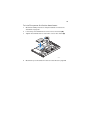
2
Loosen the thumbscrew that secures the cover to the chassis (A).
3
Pull up the cover to remove it (B).
A
B
TP02228
4
Observe the post-installation instructions described on page 40.
49
To install the power distribution board cover:
1
Observe the ESD precautions and pre-installation instructions
described on page 39.
2
Lower the power distribution board cover to the chassis (A).
3
Tighten the thumbscrew to secure the cover to the chassis (B).
B
A
TP02229
4
Observe the post-installation instructions described on page 40.
50
3 System upgrade
Configuring the storage devices
The system supports 2.5-inch storage devices. It accommodates slimline optical drives and depending on system model, can support up to
six 2.5-inch hot-plug SATA hard disk drives or eight hot-plug SAS hard
disk drives.
Caution! To maintain proper system cooling, filler panels must be
installed if a device is not replaced.
Removing and installing a hard disk drive
Note: Use only Acer-qualified SAS or SATA HDDs. To purchase a
SAS or SATA HDD, contact your local Acer representative.
Caution! To ensure proper airflow and server cooling, all drive
bays must contain either a carrier with a hard drive installed in it
or a hard disk carrier cover.
Determining drive status
Each HDD carrier features two status LED indicators to display the hard
drive status. If you are replacing a failed HDD, determine which drive
has failed by checking the drive status LED. For more information on
how to determine the drive status, refer to “Hot-plug HDD LED
indicators” on page 25.
51
To remove a HDD:
1
Observe the ESD precautions described on page 39.
2
If you are removing a failed HDD, determine which drive has failed
by checking the drive status LEDs.
3
Press the green HDD carrier latch to open the drive (A).
4
Pull out the lever and slide the carrier from the chassis (B).
B
A
5
Place the HDD carrier on a clean, static-free work surface.
6
If you are replacing a hard disk, remove the four screws that secure
the hard disk to the HDD carrier, then remove the disk from the
HDD carrier.
7
Keep the screws for later HDD installation.
52
3 System upgrade
To install a HDD:
Note: To puchase a HDD carrier, contact your local Acer
representative.
1
Perform steps 1 to 4 listed on the “To remove a HDD” section on
page 51.
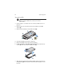
2
Remove the four screws that secure the air baffle to the HDD
carrier (A).
3
Remove the air baffle from the HDD carrier (B).
4
Save the air baffle and screws for later use.
5
Remove the HDD from its protective packaging.
6
Install a hard disk on the HDD carrier, then secure it with the four
screws (A) that came with the HDD carrier (B).
B
A
TP02231
7
With the lever still extended, slide the HDD carrier all the way into
the drive bay (A). Do not push on the lever until it begins to close
by itself.
53
8
When the lever begins to close by itself, push on it to lock the drive
assembly into place (B).
A
B
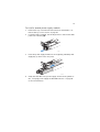
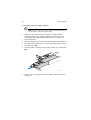
Removing and installing a slim-line optical drive
Note: The slim-line optical drive is not hot-pluggable. Before
removing or replacing the drive, you must first power down the
server, unplug the AC power cord from the system, and turn off all
peripherals devices connected to the server.
Caution! To maintain proper system cooling, a filler panel must
be installed if a device is not installed in the bay.
To remove a slim-line optical drive:
1
Observe the ESD precautions and pre-installation instructions
described on page 39.
54
2
3 System upgrade
Press the blue release lever to unlock the optical drive tray (A) and
slide the optical drive tray out through the front of the server (B).
A
B
TP02261
3
If no device will be installed in the drive bay, install the filler panel
in the drive bay.
If installing a new optical drive, see succeeding section.
To install a slim-line optical drive:
1
Observe the ESD precautions and pre-installation instructions
described on page 39.
2
If necessary, remove the old optical drive. See previous section.
3
If a filler panel is installed, remove it from the drive bay.
4
Remove the new drive from its protective packaging.
55
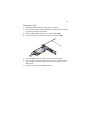
5
Install the plastic guide on the rear of the optical device, then
secure it with the two screws that came with the optical drive kit.
TP02233
6
Slide the optical drive tray into the front opening in the server.
Make sure the back end of the plastic guide plugs into the
matching connector on the backplane board.
7
Verify that the blue release lever on the tray locks into place.
8
Observe the post-installation instructions described on page 40.
56
3 System upgrade
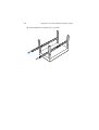
Removing and installing a PCI riser
assembly
Note: The PCI riser assembly includes an intrusion switch that
engages the system cover. The intrusion switch is provided to
allow server management software to monitor removal of the top
cover from the server.
Caution! The PCI riser assembly must be installed to maintain
proper airflow inside the server.
This section explains how to access the PCI riser assembly and remove
and install PCI cards.
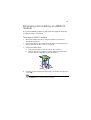
To remove the PCI riser assembly:
1
Observe the ESD precautions and pre-installation instructions
described on page 39.
2
Remove the CPU air duct. Perform the instructions described in “To
remove the CPU air duct” section on page 45.
3
Diconnect any cables attached to an installed PCI card.
4
Grasp both riser latches with thumb and forefinger, then pull up to
release the riser assembly.
57
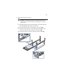
5
Lift the riser assembly from the chassis.
TP02236
6
Place the riser assembly on a clean, static-free work surface.
7
If you need to replace PCI cards. See “Removing and installing a
PCI card” on page 58.
8
Observe the post-installation instructions described on page 40.
58
3 System upgrade
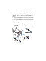
To install the PCI riser assembly:
1
Observe the ESD precautions and pre-installation instructions
described on page 39.
2
Lower the PCI riser assembly (A), aligning the four hooks on the
back edge of the riser assembly with the matching slots on the rear
of the chassis (B).
3
Press down on the assembly until the four hooks on the rear of the
riser assembly engage the chassis rear panel slots. The riser cards
will seat into the matching sockets on the mainboard.
4
Connect the cables to the installed PCI card.
5
Observe the post-installation instructions described on page 40.
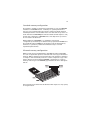
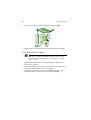
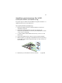
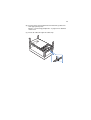
Removing and installing a PCI card
To remove a PCI card:
1
Observe the ESD precautions and pre-installation instructions
described on page 39.
2
Remove the CPU air duct. Perform the instructions described in “To
remove the CPU air duct” section on page 45.
3
Remove the PCI riser assembly from the server. See “To remove the
PCI riser assembly” section on page 56.
4
Open the rear retention clip by pushing the blue slide upward and
rotating clip to the fully open position.
59
5
When removing a full height PCI card, open the full length PCI
card retention clip on the front of the riser assembly by rotating it
90 degrees outward.
Note: The install sequence for low profile PCI cards on the
opposite side of the riser assembly is the same.
6
Pull up the card to remove it, then store the card in an antistatic
protective wrapper.
A
B
TP02241
7
Observe the post-installation instructions described on page 40.
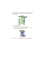
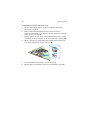
To install a PCI card:
Note: When installing PCI-X cards into the full height riser board,
the cards must be installed starting with the top slot first,
followed by the middle and then the bottom. Any card populated
in the bottom PCI slot will cause the bus to operate at 66 MHz.
1
Observe the ESD precautions and pre-installation instructions
described on page 39.
2
Remove the CPU air duct. Perform the instructions described in “To
remove the CPU air duct” section on page 45.
3
Remove the PCI riser assembly from the server. See “To remove the
PCI riser assembly” section on page 56.
4
Open the rear retention clip by pushing the blue slide upward (A)
and rotating clip to the fully open position.
60
5
3 System upgrade
When installing a full height PCI card, open the full length PCI card
retention clip on the front of the riser assembly by rotating it 90
degrees outward (B).
6
Remove the filler panel, if installed.
7
Insert the PCI card into the selected slot (C). Make sure the card is
properly seated.
B
A
C
TP02240
8
Close both retention clips.
9
Observe the post-installation instructions described on page 40.
61
Upgrading the CPU
The server supports two dual-core or quad-core Intel Xeon processors
5000 sequence with system bus speeds of 667 MHz, 1066 MHz or 1333
MHz, and core frequencies starting at 1.6 GHz.
CPU upgrading guidelines
When installing CPUs the following rules must be observed:
•
Use only Acer-qualified CPUs.
•
Each CPU socket include a CPU and heat sink.
•
When two CPUs are installed, both should have identical revision,
core voltage, and bus/core speed values.
•
When only one CPU is installed, it must be installed in CPU 1
socket.
•
System is designed to provide up to 130 W of current per
processor. Processors with higher current requirements are not
supported.
To install a CPU:
1
Observe the ESD precautions and pre-installation instructions
described on page 39.
Warning! The heat sink becomes very hot when the system
is on. NEVER touch the assembly with any metal or with
your hands.
2
Remove the CPU air duct. Perform the instructions described in “To
remove the CPU air duct” section on page 45.
3
If installing a second CPU, remove the CPU air dam first. See
“Removing the CPU air dam” section on page 47.
4
Locate the processor socket.
62
3 System upgrade
5
Push the socket retainer lever handle down and away from the
socket to release it (A), then pull the lever to a fully open, upright
position (B).
6
Push the rear tab with your finger tip to bring the front end of the
load plate up slightly (A).
7
Lift the load plate (B).
8
Remove the CPU from its protective packaging.
9
Position the CPU over the socket (A), making sure the CPU cutouts
match the socket notches, then insert the CPU into the socket (B).
Caution! The underside of the CPU has components that may
damage the socket pins if installed improperly. CPU must align
correctly with socket opening before installation. DO NOT drop
processor into the socket.
63
10 Remove the protective socket cover by grasping the socket cover
tab (A) and pulling it away from the load plate (B).
11 Store the protective socket cover for future use.
12 Close the load plate (A), then press the retainer lever down to lock
the load plate in place (B, C).
64
3 System upgrade
13 If the heat sink does not have thermal grease on the bottom, apply
thermal grease to the heat sink base.
14 Install the heatsink and fan
Caution! The heat sink has a thermal interface material (TIM) on
the underside. Use caution so that you do not damage the TIM.
(1) If a protective film is installed on the TIM, remove it.
(2) Set the heat sink over the processor, aligning the four captive
screws with the four screw posts surrounding the processor.
(3) Loosely screw in the captive screws on the heat sink corners in
a diagonal manner.
Note: Do not fully tighten one screw before tightening another.
(4) Gradually and equally tighten each captive screw until each is
firmly tightened.
2
3
4
1
TP02328
15 Observe the post-installation instructions described on page 40.
65
To remove a CPU:
If you are replacing a CPU on the system, the heat sink must first be
removed.
Important: Before removing a CPU from the mainboard, make
sure to create a backup file of all important data.
1
Observe the ESD precautions and pre-installation instructions
described on page 39.
Warning! The heat sink becomes very hot when the system
is on. NEVER touch the assembly with any metal or with
your hands.
2
Remove the CPU air duct. Perform the instructions described in “To
remove the CPU air duct” section on page 45.
3
Locate the CPU you want to remove.
4
Remove the heat sink.
(1) Loosen the four captive screws on the heat sink.
(2) Twist the heat sink lightly to break the seal between the
heatsink and the processor.
66
3 System upgrade
(3) Lift the heat sink from the processor.
Caution! If it does not pull up easily, twist the heat sink again. Do
not force the heat sink from the processor. Doing so could damage
the processor.
(4) Place the heat sink upside down on a flat surface.
Note: Wipe off the thermal grease from both the heat sink and
processor using an alcohol pad.
5
Pull the CPU socket retainer lever handle down and away from the
socket to release it.
6
Lift the load plate.
7
Pull out the CPU from the socket, then store it in an anti-static bag.
8
If installing a replacement processor, see “To install a CPU”.
9
Observe the post-installation instructions described on page 40.
67
Upgrading the system memory
Acer Altos R520 server supports eight DDR2 fully buffered DIMM slots
with four FBDIMM memory channels. Each channel can support up to 2
dual ranked DDR2 FBDIMMs. The memory channels are organized in to
two branches for support of mirrored memory configuration. Up to 8
FBDIMMs or a maximum memory size of 32 GB physical memory in
standard non-mirrored mode and 16 GB physical memory in a mirrored
configuration are supported by the server.
On the server, a pair of channels becomes a branch where each branch
consists of:
•
•
Branch 0
•
Channel A - DIMMA1 and DIMMA2
•
Channel B - DIMMB1 and DIMMB2
Branch 1
•
Channel C - DIMMC1 and DIMMC2
•
Channel D - DIMMD1 and DIMMD2
68
3 System upgrade
Memory module installation guidelines
The following rules apply when installing fully-buffered memory
modules to the server:
•
The system must have a minimum of one 512 MB FBDIMMs
installed. When installing additional memory, refer to the tables
on “Memory module population order” on page 69 for proper
population order.
•
Use only DDR2 FBDIMMs. Other DIMMs will not fit into the socket.
Attempts to force a non-DDR2 FBDIMM into a socket will damage
or the slot or the FBDIMM.
•
Hold FBDIMMs only by the edges. Do not touch the components or
gold edge connectors.
•
Install FBDIMMs with gold-plated edge connectors only.
Memory module population guidelines
The following configuration rules must be observed when populating
memory modules:
•
In a minimum memory configuration, the FBDIMM should be
installed in DIMM A1 slot.
•
Install FBDIMM pairs in the following order:
•
•
Channel A: DIMM slots A1 and A2
•
Channel B: DIMM slots B1 and B2
•
Channel C: DIMM slots C1 and C2
•
Channel D: DIMM slots D1 and D2
FBDIMMs within a given channel must be identical with respect to
size, speed, and organization.
69
Memory module population order
The tables below list the suggested DDR2 FBDIMM module population
for standard, mirrored or sparing configuration.
Standard configuration
Branch 0
Branch 1
Channel A
DIMM A1
Channel B
DIMM A2
DIMM B1
Channel C
DIMM B2
DIMM C1
Channel D
DIMM C2
DIMM D1
DIMM D2
512 MB
512 MB
512 MB
512 MB
512 MB
512 MB
512 MB
512 MB
512 MB
512 MB
512 MB
512 MB
512 MB
512 MB
512 MB
512 MB
512 MB
512 MB
512 MB
512 MB
512 MB
1 GB
1 GB
1 GB
1 GB
1 GB
1 GB
1 GB
1 GB
1 GB
1 GB
1 GB
1 GB
1 GB
1 GB
1 GB
1 GB
1 GB
1 GB
1 GB
1 GB
1 GB
2 GB
2 GB
2 GB
2 GB
2 GB
2 GB
2 GB
2 GB
2 GB
2 GB
2 GB
2 GB
2 GB
2 GB
2 GB
2 GB
2 GB
2 GB
2 GB
2 GB
2 GB
Mirrored configuration
Branch 0
Channel A
DIMM
A1
DIMM
A2
512 MB
512 MB
1 GB
1 GB
DIMM
B2
512 MB
1 GB
1 GB
512 MB
2 GB
DIMM
C1
DIMM
C2
512 MB
(Mirror)
1 GB
1 GB
(Mirror)
512 MB
(Mirror)
2 GB
(Mirror)
DIMM
D1
DIMM
D2
512 MB
(Mirror)
512 MB
(Mirror)
1 GB
(Mirror)
1 GB
(Mirror)
2 GB
(Mirror)
2 GB
Channel D
512 MB
(Mirror)
1 GB
(Mirror)
2 GB
2 GB
Channel C
512 MB
(Mirror)
1 GB
2 GB
2 GB
DIMM
B1
512 MB
512 MB
Total Memory
Branch 1
Channel B
1 GB
(Mirror)
1 GB
(Mirror)
2 GB
(Mirror)
2 GB
(Mirror)
2 GB
(Mirror)
2 GB
(Mirror)
Physical Detected
Memory by OS
2 GB
1 GB
4 GB
2 GB
4 GB
2 GB
8 GB
4 GB
8 GB
4 GB
16 GB
8 GB
70
3 System upgrade
Sparing configuration
Branch 0
Channel A
DIMM
A1
DIMM
A2
Total Memory
Branch 1
Channel B
DIMM
B1
DIMM
B2
Channel C
DIMM
C1
DIMM
C2
Channel D
DIMM
D1
DIMM
D2
512 MB 512 MB
(Sparing)
512 MB 512 MB
(Sparing)
512 MB 512 MB
(Sparing)
512 MB 512 MB
(Sparing)
512 MB 512 MB
(Sparing)
512 MB 512 MB
(Sparing)
512 MB 512 MB
(Sparing)
1 GB
1 GB
(Sparing)
1 GB
1 GB
(Sparing)
1 GB
1 GB
(Sparing)
1 GB
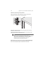
1 GB
(Sparing)
1 GB
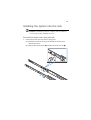
1 GB
(Sparing)
1 GB
1 GB
(Sparing)
1 GB
1 GB
(Sparing)
2 GB
2 GB
(Sparing)
2 GB
2 GB
(Sparing)
2 GB
2 GB
(Sparing)
2 GB
2 GB
(Sparing)
2 GB
2 GB
(Sparing)
2 GB
2 GB
(Sparing)
2 GB
2 GB
(Sparing)
Physical Detected
Memory by OS
1 GB
512 MB
2 GB
1 GB
4 GB
2 GB
2 GB
1 GB
4 GB
2 GB
8 GB
4 GB
4 GB
2 GB
8 GB
4 GB
16 GB
8 GB
Memory configuration overview
The system supports the following memory configuration that allow
flexibility in performance, redundancy, and ability to upgrade.
•
Standard configuration
•
Memory mirroring
•
Memory sparing
Memory mirroring and memory sparing features are mutually
exclusive, only one of these memory modes can be enabled at one time
and not both at the same time.
71
Standard memory configuration
The system is capable of supporting a minimum of only one FBDIMM
installed on the DIMM A1 slot. However, for system performance
reasons, we recommend that at least two memory modules must be
installed per branch. The modules must cover the same slot position on
both channels and FBDIMM pairs must be identical with respect to size,
speed, and organization. FBDIMMs that cover adjacent slot positions
do not need to be identical.
When adding four FBDIMMs to a standard non-mirrored
configuration, the memory modules must be populated in DIMM slots
A1 and B1 first then DIMM slots C1 and D1. It allows both memory
branches to operate in parallel and simultaneously to achieve
equivalent performance.
Mirrored memory configuration
Memory mirroring is implemented in the MCH and the system BIOS.
You can configure the system to maintain mirrored copy of the data in
memory. When operating in mirrored mode, both branches operate in
lock step. In mirrored mode, branch 1 contains a replicate copy of the
data in branch 0. The minimum FBDIMM configuration to support
memory mirroring is four FBDIMMs, populated as shown in the figure
below:
All four memory modules must be identical with respect to size, speed,
and organization.
72
3 System upgrade
To upgrade to a four FBDIMM mirrored memory configuration, four
additional FBDIMMs must be added to the system. All four memory
modules in the second set must be identical to the first with the
exception of speed. The memory controller hub (MCH) will adjust to
the low-speed FBDIMM memory.
Note: After upgrading system memory to this feature, the
memory RAS setting in the BIOS setup must be set to Mirroring
configuration. Refer to the BIOS setup’s Configure Memory RAS
and Performance screen on page 101 for more information.
Memory sparing configuration
The system provides FBDIMM sparing capabilities. Sparing is a RAS
feature that involves configuring a FBDIMM to be placed in reserve so
it can be use to replace a failed FBDIMM.
Note: FBDIMM sparing occurs within a given bank of memory and
is not supported across branches.
The system supports two types of memory sparing configurations:
•
Single branch mode sparing
In single branch mode sparing the following population rules must
be observed:
•
•
DIMM slots A1 and B1 or DIMM slots A2 and B2 must be
identical in organization, speed, and speed
•
DIMM slots A1 and A2 or DIMM slots B1 and B2 need not be
identical in organization, size and speed
•
Sparing should be enabled in the BIOS setup utility
•
System BIOS will configure rank sparing mode.
•
The largest memory size among the DIMM pairs (DIMM_A1,
DIMM_B1) and (DIMM_A2, DIMM_B2) will be selected as the
spare pair unit.
Dual branch mode sparing
Dual branch mode sparing requires that all eight FBDIMM slots be
populated and must comply with the following population rules:
73
•
•
The following FBDIMM slots must be identical in organization,
size and speed.
• DIMM slots A1 and B1
• DIMM slots C1 and D1
• DIMM slots A2 and B2
• DIMM slots C2 and D2
The following DIMM slots need not be identical in
organization, size and speed.
• DIMM slots A1 and A2
• DIMM slots C1 and C2
• DIMM slots B1 and B2
• DIMM slots D1 and D2
•
Sparing should be enabled in the BIOS setup utility
•
BIOS will configure rank sparing mode.
•
The largest memory size among the DIMM pairs (DIMM_A1,
DIMM_B1) and (DIMM_A2, DIMM_B2) and (DIMM_C1,
DIMM_D1) and (DIMM_C2, DIMM_D2), will be selected as the
spare pair units.
Note: After upgrading system memory to this feature, the
memory RAS setting in the BIOS setup must be set to Sparing
configuration. Refer to the BIOS setup’s Configure Memory RAS
and Performance screen on page 101 for more information.
To install FBDIMMs:
Caution! Use extreme care when installing a FBDIMM. Applying
too much pressure can damage the connector. FBDIMMs are keyed
and can be inserted in only one way.
Note: The number labels next to the FBDIMM slots correspond to
proper installation sequence.
1
Observe the ESD precautions and pre-installation instructions
described on page 39.
2
Remove the CPU air duct. Perform the instructions described in “To
remove the CPU air duct” section on page 45.
3
Locate the DIMM slots on the mainboard.
74
3 System upgrade
4
Open the clips on the DIMM slot(s) (A).
5
Align (B) then insert the FBDIMM into the socket (C).
6
Press the holding clips inward to lock the FBDIMM in place (D).
Note: The DIMM slot is slotted to ensure proper installation. If
you insert a FBDIMM but it does not fit easily into the socket, you
may have inserted it incorrectly. Reverse the orientation of the
FBDIMM and insert it again.
7
Observe the post-installation instructions described on page 40.
To remove FBDIMMs:
Before you can install a new DIMM in a socket, first remove any
previously installed DIMM from that socket.
Important: Before removing any DIMM from the mainboard,
make sure to create a backup file of all important data.
75
Caution! Use extreme care when removing DIMMs. Too much
pressure can damage the connector. Apply only enough pressure
on the plastic levers to release the DIMM.
1
Observe the ESD precautions and pre-installation instructions
described on page 39.
2
Press the holding clips on both sides of the DIMM slot outward to
release the DIMM (A).
3
Gently pull the DIMM upward to remove it from the DIMM slot
(B).
4
Observe the post-installation instructions described on page 40.
To reconfigure the system memory:
The system automatically detects the amount of memory installed. Run
the BIOS setup to view the new value for total system memory and
make a note of it.
76
3 System upgrade
Installing and removing a power
supply module
The server has two power supply module bays on the rear panel that
accept hot-plug power supply modules. The system ships out with only
a single power supply module installed. You have the option to
purchase an extra power supply module to provide the system with a
redundant power source. A redundant power configuration enables a
fully-configured system to continue running even if one power supply
module fails.
WARNING! To reduce the risk of personal injury or damage to
the equipment, the installation of power supply modules
should be referred to individuals who are qualified to service
server systems and are trained to deal with equipment capable
of generating hazardous energy levels.
WARNING! To reduce the risk of personal injury from hot
surfaces, observe the thermal labels on each power supply
module. You can also consider wearing protective gloves.
WARNING! To reduce the risk of personal injury from electric
shock hazards, do not open the power supply modules. There
are no serviceable parts inside the module.
Caution! Electrostatic discharge can damage electronic
components. Make sure that you are properly grounded before
handling a power supply module.
Caution! Due to chassis airflow disruption, a power supply bay
should never be vacant for more than two minutes when the
server is powered on. Exceeding five minutes might cause the
system to exceed the maximum acceptable temperature and
possibly damage the system components.
Caution! The power supply is only hot-pluggable if you have a
redundant system with two power supplies installed. If you
only have one power supply installed, before removing or
replacing the power supply, you must first take the server out
of service, turn off all peripheral devices connected to the
system, turn off the system by pressing the power button, and
unplug the AC power cord from the system or wall outlet.
77
To install a second power supply module:
1
Remove the top cover. Perform the instructions described in “To
remove the top cover” section on page 43.
2
If a filler panel is installed, use the finger hole to remove the filler
panel out of the bay (A).
TP02242
3
Insert the power supply module into the right bay, labeled power
supply bay 2, until it locks into place.
TP02243
4
Verify that the LED on the power supply are functioning. Refer to
the “Hot-plug power supply module LED indicator” on page 26
for more information.
78
3 System upgrade
To remove a power supply module:
Caution! Power supply hot-plug operations should be performed
only if a failure occurs in the power supply.
1
If there are more than one power supply modules installed,
determine which power supply module has failed. Refer to the
“Hot-plug power supply module LED indicator” on page 26 for
more information.
2
Remove the AC power cord from the power supply being replaced.
3
Press the power supply latch to release the power supply module
from the chassis (A).
4
Use the handle to pull the power supply module out of the server
(B).
B
A
TP02244
5
Install a new power supply module or install a filler panel to the
empty bay.
79
Removing and installing an ARMC/3
module
The optional ARMC/3 module provides server management firmware
and functionality to the system.
To remove an ARMC/3 module:
1
Observe the ESD precautions and pre-installation instructions
described on page 39.
2
Remove the CPU air duct. Perform the instructions described in “To
remove the CPU air duct” section on page 45.
3
4
Remove the NIC module.
a
Pull up the module to remove it from the connector.
b
Remove the three standoffs from the mainboard, then keep
the standoffs for later NIC module installation.
Hold the module both by the finger grip loop and by the opposite
corner (A).
Caution! Do not bend or twist the module.
80
3 System upgrade
5
Pull up the module to remove it from the connector (B).
6
Observe the post-installation instructions described on page 40.
To install an ARMC/3 module:
Note: Prior to installing the ARMC/3 module module, you must
remove the server management port cover module cover on the
rear of the server.
1
Observe the ESD precautions and pre-installation instructions
described on page 39.
2
Remove the CPU air duct. Perform the instructions described in “To
remove the CPU air duct” section on page 45.
3
Insert the standoff into the hole in the ARMC/3 module. The
standoff installs on the bottom side of the module (A).
81
4
Attach the module to the ARMC/3 module connector on the
mainboard and snap the standoff into the matching hole on the
mainboard (B).
5
Install the NIC module.
6
a
Install the three standoffs to the mainboard.
b
Attach the module to the NIC module connector on the
mainboard and matching standoff holes.
Observe the post-installation instructions described on page 40.
82
3 System upgrade
Installing and removing the SAS
hardware RAID components
The system supports SAS hardware RAID through the active mid-plane
and backplane board. The server platform supports SAS hardware RAID
0, 1, 5, 6 (when available), 10, and 50 levels. Functionality for SAS
hardware RAID is enabled by using the following components:
•
RAID activation key and RAID cache
The RAID activation key works in conjunction with the RAID cache
to provide hardware RAID.
•
RAID BBU
If power to the storage I/O processor drops below specifications,
the RAID BBU maintains the contents of the DIMM by keeping the
DIMM in self-refresh mode until power is restored. After power is
restored, data can be safely written to drives, maintaining the
integrity of the disk array.
Installing and removing the RAID activation key
and RAID cache
To install the RAID activation key and RAID cache:
1
Observe the ESD precautions and pre-installation instructions
described on page 39.
2
Remove the power distribution board cover. Perform the
instructions described in “To remove a power distribution module
cover” section on page 48.
3
Remove the RAID activation key from its protective packaging.
4
Align then insert the activation key into the RAID activation key
connector on the active mid-plane board (A).
5
Locate the RAID cache memory (DDR-2) slot on the active
mid-plane board.
83
6
Open the clips on the slot (B).
7
Align then insert the RAID cache into the slot (C).
A
B
C
B
AF000904
8
Press the holding clips inward to lock the RAID cache in place.
9
Observe the post-installation instructions described on page 40.
To remove the RAID activation key and RAID cache:
1
Observe the ESD precautions and pre-installation instructions
described on page 39.
2
Remove the power distribution board cover. Perform the
instructions described in “To remove a power distribution module
cover” section on page 48.
3
Insert the tip of a small flat-bladed screwdriver under the plastic
tab on the retainer holding the activation key to the active midplane board.
4
Gently push down to detach the activation key (A).
5
Press the holding clips on both sides of the slot outward to release
the RAID cache (B).
84
6
3 System upgrade
Gently pull the RAID cache upward to remove it from the slot (C).
A
B
B
C
AF000905
7
Close the clips.
8
Store the RAID activation key and RAID cache in an anti-static bag.
9
Observe the post-installation instructions described on page 40.
Installing and removing the RAID BBU
To install the RAID BBU:
1
Observe the ESD precautions and pre-installation instructions
described on page 39.
2
Remove the power distribution board cover. Perform the
instructions described in “To remove a power distribution module
cover” section on page 48.
3
Open the BBU case lid (A), then connect the power cable to the
power cable connector inside the battery pack (B).
85
4
Close and latch the BBU case lid.
5
Align the two hooks on the underside of the RAID BBU with the
matching chassis tabs, then slide toward the power supply to lock
into place (C).
6
Connect the power cable to the rear of the BBU and the RAID BBU
connector on the active mid-plane board (D).
D
C
A
B
TP02257
7
Observe the post-installation instructions described on page 40.
To remove the RAID BBU:
1
Observe the ESD precautions and pre-installation instructions
described on page 39.
2
Remove the power distribution board cover. Perform the
instructions described in “To remove a power distribution module
cover” section on page 48.
3
Disconnect the BBU power cable from the rear of the RAID BBU
and the mid-plane board (A).
86
4
3 System upgrade
Slide the RAID BBU forward and lift from the chassis (B).
A
B
TP02258
5
Store the RAID BBU in an antistatic protective wrapper.
6
Observe the post-installation instructions described on page 40.
87
Installing and removing the SATA
software RAID activation key
The system supports SATA software RAID 5 through the installation of
a RAID activation key on the mainboard.
To install the RAID activation key:
1
Observe the ESD precautions and pre-installation instructions
described on page 39.
2
Remove the power distribution board cover. Perform the
instructions described in “To remove a power distribution module
cover” section on page 48.
3
Locate the SATA software RAID activation key connector on the
mainboard.
4
Remove the RAID activation key from its protective packaging.
5
With the lighter colored edge of the RAID activation key pointing
to the edge of the mainboard, push the key onto the connector on
the mainboard.
6
Observe the post-installation instructions described on page 40.
88
3 System upgrade
To remove the RAID activation key:
1
Observe the ESD precautions and pre-installation instructions
described on page 39.
2
Remove the power distribution board cover. Perform the
instructions described in “To remove a power distribution module
cover” section on page 48.
3
Tightly squeeze the two ends of the RAID activation key to create
a small gap at the lock points on the front and rear of the key (A).
4
While continuing to squeeze the ends, wiggle the key back and
forth while pulling it from the connector (B).
5
Store the RAID activation key in an anti-static bag.
6
Observe the post-installation instructions described on page 40.
4 BIOS setup
This chapter gives information about the system
BIOS and discusses how to configure the system
by changing the settings of the BIOS parameters.
91
BIOS setup
BIOS setup is a hardware configuration program built into the system's
Basic Input/Output System (BIOS). Since most systems are already
properly configured and optimized, there is no need to run this utility.
The BIOS setup utility stores basic settings for your server. You will need
to run this utility under the following conditions:
•
When changing the system configuration
•
When a configuration error is detected by the system and you are
prompted ("Run Setup" message) to make changes to the BIOS
setup
Note: If you repeatedly receive Run Setup messages, the battery
may be bad. In this case, the system cannot retain configuration
values in CMOS. Ask a qualified technician for assistance.
•
When redefining the communication ports to prevent any conflicts
•
When changing the password or making other changes to the
security settings
BIOS setup loads the configuration values in a battery-backed
nonvolatile memory called CMOS RAM. This memory area is not part of
the system RAM which allows configuration data to be retained when
power is turned off.
Before you run BIOS setup, make sure that you have saved all open
files. The system reboots immediately after you close the setup.
92
4 BIOS setup
Entering BIOS setup
Power on the server to start the system POST process. During bootup,
press F2 to enter the BIOS setup screen.
Note: You must press F2 while the system is booting. This key
does not work during any other time.
There are several tabs on the setup screen corresponding to the eight
primary BIOS menus.
•
Main
•
Advanced
•
Security
•
Server Management
•
Boot Options
•
Boot Manager
•
Error Manager
•
Exit
The parameters on the screens shown in this User’s Guide display
default system values. These values may not be the same as those in
the system.
Note the following reminders when moving around the setup screen.
•
Use the Left and Right arrow keys to move to the next page or to
return to the previous screen.
•
Use the Up and Down arrow keys to select an item.
•
Use the + and - keys to select an option.
Note: You can configure a parameter that is enclosed in square
brackets. Grayed-out items have fixed settings and are not
user-configurable.
•
Use the Enter key to display a submenu screen.
Note: When a parameter is preceeded by a [>], it means that a
submenu screen is available.
93
•
Press F1 for General Help on using the BIOS setup.
•
Press F9 to load the default configuration.
•
Press F10 to save changes and close the BIOS setup.
•
Press Esc to close the BIOS setup.
In the descriptive table following each of the screen illustrations,
settings in boldface are the default and suggested parameter settings.
94
4 BIOS setup
Using the BIOS menus
Main
The Main menu displays basic and important information about the
system. These information are necessary for troubleshooting and may
be required when asking for technical support. These entries are for
your reference only and are not user-configurable.
The System Date and System Time parameters lets you define the
sytem’s time and date settings. The real-time clock keeps the system
date and time. After setting the date and time, you do not need to
enter them every time you turn on the system. As long as the internal
battery remains good and connected, the clock continues to keep the
date and time accurately even when the power is off.
Parameter
Description
BIOS Version
Version of the BIOS.
BIOS Build
Date
Date BIOS was created.
Option
95
Parameter
Description
Processor
Specification of the processor currently
installed in the server.
Total Memory
Indicates the size of the system memory.
Quiet Boot
When Enabled, the BIOS splash screen is
displayed during startup.
Option
Enabled
Disabled
When Disabled, the diagnostic messages
are displayed during startup.
POST Error
Pause
If Enabled, the system will pause if an error
is found during POST.
System Date
Sets the date following the month-day-year
format. Valid values for weekday, month,
day, and year are:
Month: Jan, Feb, Mar, Apr, May, Jun, Jul,
Aug, Sep, Oct, Nov, Dec
Day: 1 to 31
Year: 1998 to 2099
System Time
Sets the time following the hour-minutesecond format. Valid values for hour,
minute, and second are:
Hour: 00 to 23
Minute: 00 to 59
Second: 00 to 59
Disabled
Enabled
96
4 BIOS setup
Advanced
The Advanced menu contains parameter values that define how the
system behaves on startup.
Warning! Be cautious in setting parameter values in the
Advanced menu as any incorrect value may cause the
system to malfunction.
Press Enter to enter the submenu screen of the parameters shown in
the screen below.
97
Processor
The Processor submenu displays CPU settings such as type, actual
speed, cache size and other CPU related settings.
Parameter
Description
Option
Core Frequency
Indicates the processor clock speed.
System Bus
Frequency
Indicates the processor front side bus
speed.
Hyper
Threading
Technology
Enables or disables the Hyper-Threading
Technology function of the processor.
Enabled
Enhanced Intel
SpeedStep
Technology
When set to Enabled, this feature allows
the OS to reduce power consumption.
When set to Disabled, the system
operates at maximum CPU speed.
Enabled
Disabled
Dual Core
Enables or disables the secondary
processor core.
Enabled
Disabled
Disabled
98
4 BIOS setup
Parameter
Description
Option
Virtualization
Technology
Enables or disables the system to run
multiple operating systems and
applications in different partition.
Disabled
Enabled
Execute Disable
Bit
When Enabled, the processor disables
code execution when a worm attempts
to insert a code in the buffer preventing
damage and worm propagation.
Enabled
Disabled
When Disabled, the processor forces the
Execute Disable Bit feature flag to
always return to 0.
Note: This parameter is hidden if the
processor does not support this function.
Hardware
Prefetcher
Enables or disables the speculative
prefetch unit within the processor(s).
Note: Changing this feature may affect
system performance.
Enabled
Disabled
Adjacent Cache
Line Prefetch
When Enabled, cache lines are fetched
in pairs (even line + odd line)
When Disabled, only current cache line
required is fetched.
Enabled
Disabled
Note: Changing this feature may affect
system performance.
Processor
Re-Test
When Enabled, all processors will be
activated and retested on the next boot.
This option will be automatically reset to
disable on the next boot.
Processor #
Information
Press Enter to access the Processor #
Information submenu.
Disabled
Enabled
99
Processor # Information
The screen below appears when you select the Processor #1 or 2
Information menu.
100
4 BIOS setup
Memory
The Memory submenu displays the total amount of memory installed,
the number of memory modules installed, and the current memory
configuration.
Parameter
Description
Total Memory
Indicates the total amount of onboard memory. The
memory size is automatically detected by BIOS during
the POST. If you install additional mamory, the system
automatically adjusts this parameter to display the new
memory size.
Effective
Memory
Indicates the total effective memory installed in the
server.
Current
Configuration
Displays the current memory configuration.
Current Memory
Speed
Indicates the speed of the memory module(s) installed
in the server.
101
Parameter
Description
Configure
Memory RAS and
Performance
Press Enter to access the Configure Memory RAS and
Performance submenu.
DIMM
information
Indicates the DIMM and DIMM slot status.
Configure Memory RAS and Performance
The screen below appears when you select the Configure Memory RAS
and Performance menu. This submenu allows you to view memory
configuration details and configure the memory modules in the server.
Parameter
Description
Capabilities
Displays the characteristics of the selected
memory configuration.
Option
102
4 BIOS setup
Parameter
Description
Option
Memory
MIrroring
Possible
Indicates whether a mirrored
configuration is possible with the current
installed memory.
If No is displayed, you may need to install
more memory to meet the requirements
of the selected configuration.
Yes
No
Memory
Sparing
Possible
Indicates whether a sparing
configuration is possible with the current
installed memory.
If No is displayed, you may need to install
more memory to meet the requirements
of the selected configuration.
Yes
Select Memory
RAS
Configuration
Select a memory RAS configuration/
option.
RAS
Disabled
Sparing
No
Mirroring
103
ATA Controller
The ATA Controller submenu lets you define the parameter settings
related to the hard disk(s).
Parameter
Description
Option
Onboard PATA
Controller
Enables or disables the integrated
parallel ATA controller.
Enabled
Onboard SATA
Controller
Enables or disables the integrated Serial
ATA controller.
Enabled
SATA Mode
When set to Enhanced, it will enable all
SATA connectors as individual
connectors.
Enhanced
Legacy
When set to Legacy, it will enable
primary and secondary channels on SATA
connectors.
Disabled
Disabled
104
4 BIOS setup
Parameter
Description
Option
AHCI Mode
Enables or disables access to all six SATA
connectors via the AHCI (Advanced Host
Controller Interface) Option ROM. AHCI
is an interface specification that allows
the storage driver to enable advanced
SATA features such as Native Command
Queuing and hot plug.
Disabled
Enabled
Note: Requires an AHCI aware OS.
Configure SATA
as RAID
Enables or disables the software RAID
technology Option ROM within the
ESB2-E controller.
Primary IDE
Master
Indicates the controller that is set as
primary master.
Primary IDE
Slave
Indicates the controller that is set as
primary slave.
SATA Port
0, 1, 2, 3
Indicates the SATA HDD connected to
the SATA connector.
Disabled
Enabled
105
Mass Storage
The Mass Storage submenu displays the status of the mass storage
controller.
Parameter
Description
Option
SAS Controller
Enables or disables the SAS controller.
Enabled
Disabled
SAS Option
ROM
If enabled, initializes the the embedded
SAS device Option ROM.
Enabled
Configure SAS
as SW RAID
Enables or disables the Embedded Server
RAID Technology on the SAS connectors.
Disabled
Enabled
ROMB setup
Indicates if integrated RAID is enabled
or not.
RAID
Activation Key
Indicates if the RAID activation key is
installed or not.
Disabled
106
4 BIOS setup
Serial Port
The Serial Port submenu lets you define the parameter settings for the
system’s serial port.
Parameter
Description
Option
Serial A Enable
Enables or disables the onboard serial A
port.
Enabled
Set the base I/O address for the serial A
port.
3F8
2F8
Address
Disabled
2E8
3E8
IRQ
Serial B Enable
Set the interrupt request line for the
serial A port.
4
Enables or disables the onboard serial B
port.
Enabled
Disabled
3
107
Parameter
Description
Option
Address
Set the base I/O address for the serial B
port.
2F8
3E8
2E8
3F8
IRQ
Set the interrupt request line for the
serial B port.
3
4
USB Confguration
The USB Configuration submenu allows you specify settings for USB
devices.
Parameter
Description
Option
USB Controller
Enables or disables the USB controller.
If disabled, all the USB controllers will be
turned off and inaccessible to the OS.
Enabled
Disabled
108
4 BIOS setup
Parameter
Description
Option
Legacy USB
Support
Enables or disables the support for
legacy USB devices.
Enabled
Disabled
Auto
Port 60/64
Emulation
Enables or disables the I/O port 60/64h
emulation support.
This parameter is enabled for complete
USB keyboard legacy support for nonUSB aware OS.
Enabled
Disabled
Device Reset
Timeout
Select the number of seconds POST waits
for the USB mass storage device after
the start unit command.
20 Sec
10 Sec
When set to Auto, USB mass storage
devices with less than 530 MB will be
emulated as a floppy and the remaining
as hard drives.
The Forced FDD option can be used to
force a formatted HDD to boot as a FDD.
Auto
Sets the transfer rate at Hi Speed
(480 Mbps) or Full Speed (12 Mbps).
Enabled
Storage
Emulation
USB 2.0
Controller
30 Sec
40 Sec
Floppy
Forced FDD
CD-ROM
Hard Disk
Disabled
109
PCI
The PCI submenu lets you specify settings that are related to the
onboard controllers. enable or disable the ROM scan of a device
installed in the selected PCI slot. It also enables or disables posting of a
16-bit legacy ROM from the plug-in fiber channel card.
Parameter
Description
Option
PCI Memory
Mapped IO
Space
This selects the amount of memory that is
reserved for PCI address space below 4GB
for PCI devices.
2.50 GB
2.75 GB
3.00 GB
3.25 GB
3.50 GB
Onboard Video
Enables or disables the onboard VGA
controller.
Enabled
Disabled
Dual Monitor
Video
Select a graphic controller as a primary
boot device.
Disabled
Note: This parameter will be disabled
when the Onboard Video is set to
Disabled.
Enabled
110
4 BIOS setup
Parameter
Description
Option
Onboard NIC
ROM
Enables or disables both channels of the
embedded LAN.
Note: If disabled, NIC1 and NIC2 cannot
be used to boot the system.
Enabled
Disabled
NIC 1 or 2 MAC
Address
Indicates the media access control of the
system’s LAN controller.
I/O
Acceleration
Technology
Enables or disables the onboard LAN’s
I/O Acceleration Technology.
Enabled
Disabled
111
System Acoustic and Performance Configuration
The System Acoustic and Performance Configuration submenu lets you
set the system fan performance option.
Parameter
Description
Option
Set Fan
Profile
Select the Fan Control Profile that
will be used to cool the system.
Performance
Altitude
When set to less than 300 m
(<= 980 ft), it will provide the best
performance option for servers
operating at or near sea level.
When set to 301m - 900m (980 ft 2950 ft), it will provide the best
performance option for servers
operating at moderate altitudes
above sea level.
When set to higher than 900m (>2950
ft), it will provide the best
performance option for servers
operating at high elevations above
sea level.
301 m - 900 m
300 m or less
Acoustics
Higher than 900
m
112
4 BIOS setup
Security
The Security menu allows you to safeguard and protect the system
from unauthorized use by setting up access passwords.
Parameter
Description
Option
Administrator
Password
Prevents unauthorized access to the
BIOS setup utility.
Not Installed
User Password
Secures the system against unauthorized
use. Once you set this password, you
have to type it whenever you boot the
system. User password is available only
when an Administrator password is set.
Not Installed
Administrator
Password
Press Enter to change the Administrator
password.
User
Password
Press Enter to change the User
password.
Installed
Installed
113
Parameter
Description
Option
Front Panel
Lockout
When Enabled, the front panel power
and reset buttons will be locked. The
power and reset operation must be
controlled via system management
interface.
Disabled
Enabled
To set a Administrator/User password
1
Use the up/down keys to highlight a password parameter (Set
Administrator Password or Set User Password) then press Enter.
A password box will appear.
2
Type a password then press Enter.
The password may consist of up to seven alphanumeric characters
(A-Z, a-z, 0-9).
3
Retype the password to verify the first entry then press Enter
again.
After setting the password, the system automatically sets the
chosen password parameter to Installed.
To change the Administrator/User password
1
Use the up/down keys to highlight either change password
parameters (Change Administrator Password or Change User
Password) then press Enter.
2
Type the original password then press Enter.
3
Type a new password then press Enter.
4
Retype the password to verify the first entry then press Enter
again.
To remove the User password
1
Use the up/down keys to highlight the Clear User Password
parameter then press Enter.
2
Enter the current password then press Enter.
3
Press Enter twice without entering anything in the new and
confirm password fields.
After doing this, the system automatically sets the User password
parameter to Not Installed.
114
4 BIOS setup
Server Management
The Server Management submenu lets you specify the appropriate
settings for the system’s event handling function.
The system event log enables you to record and monitor events that
occur in the system (eg., system temperature changes, fan stops, overtemperature, over-voltage, fan failures, etc.).
Parameter
Description
Option
Assert NMI on
SERR
Enables or disables the PCI bus SERR
(system error) support.
Enabled
Assert NMI on
PERR
Enables or disables the PCI bus PERR
(parity error) support.
Note: This parameter is disabled when
the NMI on SERR is disabled.
Enabled
Disabled
Disabled
115
Parameter
Description
Option
Resume on
AC Power
Loss
Defines the mode of operation if a
power loss occurs.
When set to Stay Off, the system
remains off after power shutdown.
Stay Off
Last State
Reset
When set to Last State, the system
returns to the state it was prior to the
AC power loss.
When set to Reset, the system will turn
on after power is restored.
Clear System
Event Log
Deletes all events in the System Event
Log.
Disabled
Enabled
FRB-2 Enable
When Enabled, the BMC (Baseboard
Management Controller) will reset the
system if BIOS does not complete the
POST before the FRB-2 (Fault Resilient
Booting) timer expires.
Enabled
Enables or disables the BIOS timer. It
helps to determine if the OS has
loaded successfully or followed the OS
boot watchdog timer policy.
Disabled
Enabled
O/S Boot
Watchdog
Timer
The BIOS timer can only be shut off
using the management software after
the OS loads.
Console
Redirection
Press Enter to access the Console
Redirection submenu.
System
Information
Press Enter to access the System
Information submenu.
Disabled
116
4 BIOS setup
Console Redirection
The Console Redirection submenu lets you enable or disable the
console redirection parameters for server management tasks over the
serial port.
117
System Information
The System Information submenu displays basic information about the
server unit.
118
4 BIOS setup
Boot Options
The Boot Options menu allows you to set the network device priority
during system bootup. It also displays information about the installed
storage devices.
Parameter
Boot Timeout
Description
Option
Sets the automatic boot time-out value.
10
Note: A value ot 65535 will disable the
timeout completely.
1
Boot Option 1
Sets the device from which the system
will first attempt to boot up.
Boot Option 2
Sets the device from which the system
will attempt to boot up when the first
attempt failed.
Boot Option 3,
4, or 5
Sets the device from which the system
will attempt to boot up when the first,
second, third, and fourth attempts
failed.
119
Parameter
Description
CD-ROM Order
Specifies the boot device priority
sequence for available CD drives.
Floppy Order
Specifies the boot device priority
sequence for available FDD.
Network
Device Order
Specifies the boot device priority
sequence for available network devices.
Option
120
4 BIOS setup
Network Device #
The Network Device # submenu lets you specify the preferred settings
for system bootup.
Parameter
Description
Network
Device #
Sets the boot order of the Bootstrap
Entry Vector Devices. Network devices
are devices which have a bootable
Option ROM such as a network card or
onboard network controller.
Option
121
Boot Manager
The Boot Manager menu lets you set the device priority during system
bootup. The server will attempt to boot from the first device on the
list. If the first device is not available, it will continue down the list until
it reaches an available device. Select a boot option, then press Enter.
122
4 BIOS setup
Error Manager
The Error Manager menu lets you view the system POST errors
detected by the system.
123
Exit
The Exit menu displays the various options to quit from the BIOS setup.
Highlight any of the exit options then press Enter.
Parameter
Description
Save Changes and Exit
Saves changes made and close the BIOS setup.
Discard Changes and
Exit
Discards changes made and close the BIOS setup.
Save Changes
Saves changes made in the BIOS setup.
Discard Changes
Discards all changes made in the BIOS setup.
Restore Defaults
Loads the default settings for all BIOS setup
parameters. Setup defaults are quite demanding
in terms of resources consumption. If you are
using low-speed memory chips or other kinds of
low-performance components and you choose
to load these settings, the system might not
function properly.
124
4 BIOS setup
Parameter
Description
Save as User Default
Values
Saves current values to be restored later.
Restore User Default
Values
Restores previously saved user default values.
125
Upgrading the BIOS
The upgrade utility allows you to upgrade the BIOS in the flash
memory. To prepare to upgrade the BIOS, you need to record the
current BIOS settings and download the BIOS image file to a temporary
folder on your hard drive or a USB flash memory device.
To record the current BIOS settings:
1
Run BIOS setup. See “Entering BIOS setup” on page 92.
2
Write down the current settings in the BIOS setup utility.
To download the BIOS image file:
Download the image file to a temporary folder on your hard drive or a
USB flash memory device.
Note: Review the instructions and release notes that are provided
in the Readme file distributed with the BIOS image file before
attempting a BIOS upgrade. The release notes contain critical
information regarding jumper settings, specific fixes, or other
information to complete the upgrade.
To upgrade the BIOS:
Follow the instructions in the Readme file that came with the BIOS
upgrade. When the update completes, remove the bootable media
from which you performed the upgrade.
Note: Do not power down the system during the BIOS update
process. The system will reset automatically when the BIOS update
process is completed. You may encounter a CMOS checksum error
or other problem after reboot. It this happens, shut down the
system and boot it again. CMOS checksum errors require that you
enter Setup, check your settings, save your settings, and exit
Setup.
126
4 BIOS setup
5 Troubleshooting
This chapter provides possible solutions for specific
problems. If you cannot correct the problem, contact
your local Acer representative or authorized dealer
for assistance.
129
Troubleshooting
This chapter helps you identify and solve problems that might occur
while you are using the system.
For any issue, first ensure that you are using the latest firmware and
files. Firmware upgrades include updates for BIOS, the BMC, FRUSDR,
and the HSC. In addition to the server firmware and files, make sure to
update any drivers used for components you have installed in your
system, such as video drivers, network drivers and SAS drivers.
If you are unable to resolve your server problems on your own, contact
your dealer or local Acer representative for assistance.
Resetting the system
Before going through in-depth troubleshooting, attempt first to reset
the system using one of the methods below.
To do this
Press
Soft boot reset to clear the system memory and reload the
operating system.
Ctrl+Alt+Del
Clear system memory, restart POST, and reload the OS.
Reset button*
Cold boot reset. Turn the system power off and then on.
This clears system memory, restarts POST, reloads the OS
and halts power to all peripherals.
Power button
G=^î~áä~ÄäÉ=çå=ëóëíÉã=ïáíÜ=ÑìääJÑìåÅíáçå=Åçåíêçä=é~åÉä=ÅçåÑáÖìê~íáçåK=
Problems following initial system installation
Problems that occur at initial system startup are usually caused by an
incorrect installation or configuration. Hardware failure is a less
frequent cause. If the problem you are experiencing is with a specific
software application, see "There is problem with the application
software" on page 136.
130
5 Troubleshooting
First steps checklist
•
AC power available at the wall outlet?
•
Are the power supplies plugged in? Check the AC cable(s) on the
back of the chassis and at the AC source.
•
Are all cables correctly connected and secured?
•
Is the processor fully seated in the socket on the mainboard?
•
Are all standoffs in the proper location and not touching any
components, causing a potential short?
•
Are all expansion boards fully seated in their slots on the PCI riser
assembly?
•
Are all jumper settings on the mainboard correct?
•
Are all jumper and switch settings on expansion boards and
peripheral devices correct? If applicable, ensure that there are no
conflicts - for example, two expansion boards sharing the same
interrupt.
•
Are all peripheral devices installed correctly?
•
Are all device drivers properly installed?
•
Are the configuration settings made in the BIOS setup correct?
•
Is the operating system properly loaded? Refer to the operating
system documentation.
•
Did you press the system power button on the control panel to
turn the server on (power indicator should be lit)?
•
Is the system power cord properly connected to the system and
plugged into an outlet for 100-127 V or 200-240 V?
•
Are all integrated components from the tested components lists?
Check the tested memory, and chassis lists, as well as the supported
hardware and operating system list.
131
Hardware diagnostic testing
This section provides a more detailed approach to identifying a
hardware problem and locating its source.
Caution! Before disconnecting any peripheral cables from the
system, turn off the system and any external peripheral devices.
Failure to do so can cause permanent damage to the system and/
or the peripheral device.
1
Turn off the system and all external peripheral devices. Disconnect
each of device from the system, except for the keyboard and the
video monitor.
2
Make sure the system power cord is plugged into a properly
grounded AC outlet.
3
Make sure your video display monitor and keyboard are correctly
connected to the system. Turn on the video monitor. Set its
brightness and contrast controls to at least two thirds of their
maximum ranges (see the documentation supplied with your video
display monitor).
4
If the operating system normally loads from the hard disk drive,
make sure there is no disc in the optical drive.
5
If the power indicator does light, attempt to boot from a diskette
or disc.
6
Turn on the system. If the power indicator on the control panel
does not light, see “Power indicator does not light” on page 132.
Verifying proper operation of key system lights
As POST determines the system configuration, it tests for the presence
of each mass storage device installed in the system. As each device is
checked, its activity light should turn on briefly. Check if the HDD
activity indicator lights briefly? If not, see “HDD activity indicator does
not light.” on page 133.
132
5 Troubleshooting
Confirming loading of the OS
Once the system boots up, the operating system prompt appears on
the screen. The prompt varies according to the operating system. If the
operating system prompt does not appear, see "No Characters Appear
on Screen" on page 137.
Specific problems and corrective actions
The following contains specific problems that may arise during the use
of your server. Possible solutions are listed for each problem.
Power indicator does not light.
Do the following:
•
Make sure the power button on the control panel is turned on.
•
Make sure the power cord is connected correctly.
•
Make sure that the wall outlet has power. Test it by plugging
another device.
•
Remove all expansion cards and see if the system boots. If
successful, add the cards back in one at a time with a reboot
between each addition.
•
Make sure the memory modules comply with the system
requirements.
•
Make sure the memory modules have been populated according
to the system requirements.
•
Remove and reseat the memory modules.
•
Make sure the CPU comply with the system requirements.
•
Make sure the CPU is populated according to the system
requirements.
•
Remove and reseat the CPU.
•
Make sure the chassis standoffs are installed on the corresponding
mounting holes. Misplaced standoffs may have contact to the pins
on the bottom of the mainboard and cause a short.
133
Server boot does not complete POST
Do the following:
•
Make sure the CPU is properly seated.
•
Check the BIOS release notes to ensure the BIOS installed on the
platform supports the stepping and the family of processors
currently installed.
Server does not recognize all of the processors installed
Do the following:
•
Make sure the CPU is properly seated.
•
Make sure the CPU complies with the system requirements.
•
Make sure the CPU is populated according to the system
requirements.
•
Remove and reseat the CPU.
HDD activity indicator does not light.
Do the following:
•
Make sure the drive is not disabled in the BIOS setup utility.
•
Make sure the drive is compatible.
•
Make sure you have not exceeded the power budget for the
server.
ODD (optical disk drive) activity indicator does not light.
Do the following:
•
Make sure the ODD and plastic guide are properly connected. See
page 54 for detailed installation instructions.
•
Check that relevant switches and jumpers on the drive are set
correctly.
•
Check that drive is properly configured.
•
Check that onboard IDE controller is enabled in the BIOS setup.
134
5 Troubleshooting
ODD tray cannot be ejected.
•
Insert the tip of a paperclip into the small hole on the ODD drive.
Slowly pull the tray out from the drive until the tray is fully
extended then remove the disc.
ODD drive cannot read a disc.
Do the following:
•
Make sure you are using the correct type of disc.
•
Make sure the disc is properly seated in the drive.
•
Make sure the disc is unscratched.
•
Make sure ODD and plastic guide are properly connected.
Hard drives are not recognized.
Do the following:
•
Make sure the disk controller is not disabled in the BIOS setup.
•
Make sure the drive is compatible.
Bootable CD drive is not detected.
Make sure the Boot Options setting in the BIOS setup utility is
configured to allow the CD drive to be the first bootable device.
New memory modules installed are not detected.
Do the following:
•
Make sure the memory modules are properly seated on the DIMM
slots.
•
Make sure the memory modules comply with the system
requirements.
135
•
Make sure the memory modules have been populated according
to the system requirements.
External device connected to a USB connector does not work.
Do the following:
•
Reduce the number of external devices connected to a USB hub.
•
Refer to the documentation that came with the device.
Server cannot connect to a network
•
Make sure the network cable is securely attached to the correct
connector at the system rear panel.
•
Try a different network cable.
•
Make sure you are using the correct and the current drivers.
•
Make sure the driver is loaded and the protocols are bound.
Problems with the network
Network status indicator does not light.
Do the following:
•
Check the cabling and network equipment to make sure that all
cables are properly connected.
•
Reinstall the network drivers.
•
Try another port or hub on the switch.
Diagnostics pass but the connection fails.
Make sure the network cable is securely attached.
136
5 Troubleshooting
The controller stopped working when an adapter was installed.
•
Make sure the cable is connected to the port from the onboard
network controller.
•
Make sure the other adapter supports shared interrupts and your
OS supports shared interrupts.
•
Try reseating the adapter.
The adapter stopped working without apparent cause.
•
Try reseating the adapter first, then try a different slot if necessary.
•
The network files driver may be corrupt or deleted. Delete and
reinstall the drivers.
•
Run the diagnostics.
Network activity indicator does not light.
Do the following:
•
Make sure the correct network drivers are loaded on the system.
•
Network might be idle. Try accessing the server.
Server hangs when the drivers are loaded.
Change the PCI interrrupt settings.
There is problem with the application software.
Do the following:
•
Verify that the software is properly configured for the system.
Refer to the software installation and operation documentation
for instructions on setting up and using the software.
•
Try a different version of the software to see if the problem is with
the copy you are using.
•
Make sure all cables are properly connected.
137
•
If other software runs correctly on the system, contact your vendor
about the defective software.
No characters appear on the screen.
Check the following:
•
Is the keyboard functioning? Test it by turning the “Num Lock”
function on and off to make sure the Num Lock light is
functioning.
•
Is the video monitor plugged in and turned on? If you are using a
switch box, is it switched to the correct system?
•
Are the brightness and contrast controls on the video monitor
properly adjusted?
•
Is the video monitor signal cable properly installed?
•
Does this video monitor work correctly if plugged into a different
system?
•
Is the onboard video controller enabled in the BIOS setup?
•
Remove all expansion cards and see if the system boots. If
successful, add the cards back in one at a time with a reboot
between each addition.
•
Make sure the memory modules comply with the system
requirements.
•
Make sure the memory modules have been populated according
to the system requirements.
•
Remove and reseat the memory modules.
•
Make sure the CPU comply with the system requirements.
•
Make sure the CPU is populated according to the system
requirements.
If you are using a video controller board, do the following:
1
Verify that the video works using the onboard video controller.
2
Verify that the video controller board is fully seated in the
mainboard connector.
3
Reboot the system for changes to take effect.
4
If there are still no characters on the screen after you reboot the
system and POST emits a beep code, write down the beep code
you hear. This information is useful for your service representative.
138
5
5 Troubleshooting
If you do not receive a beep code and characters do not appear,
the video display monitor or video controller may have failed.
Contact your service representative or authorized dealer for help.
Characters are distorted or incorrect.
Check the following:
•
Are the brightness and contrast controls properly adjusted on the
video monitor? Refer to the documentation that came with the
video monitor.
•
Are the video monitor’s signal and power cords properly
connected.
•
Is the video monitor working correctly when plugged into a
different system?
System cooling fan do not rotate properly.
If the system cooling fan is not operating properly, it is an indication of
possible system component failure.
Check the following:
•
Is the power indicator lit? If not, see “Power indicator does not
light.” on page 132 .
•
Have any of the fan motors stopped? Use the server management
subsystem to check the fan status.
•
Have your fans speeded up in response to an overheating
situation?
•
Have your fans speeded up in response to a fan that has failed?
139
Error beep codes
BIOS POST error beep codes
The following table lists the POST error beep codes. Prior to system
video initialization, BIOS uses these beep codes to inform you of error
conditions. The beep code occurs only when a critical error occurs or
when the BIOS fails to boot to the operating system. Not all error
conditions are supported by the BIOS beep codes.
Number
of Beeps
Description
1, 2, or 3
Memory error
4 – 7 or
9 – 11
Fatal error indicating a possible serious system problem
8
Video error
140
5 Troubleshooting
Troubleshooting BIOS POST error beep codes
The following table lists the possible beep codes thay may occur while
using the system and is followed by solutions to the situation.
Number
of beeps
1, 2, or 3
Troubleshooting action
• Make sure the memory modules are properly seated on the
DIMM slots.
• Make sure the memory modules comply with the system
requirements.
• Make sure the memory modules have been populated
according to the system requirements.
4-7, 9-11
• Indicates a fatal error. Consult your dealer or local Acer
representative for assistance.
• If beep codes are generated even when all PCI cards are
absent, consult your system manufacturer’s technical
support.
• Check for a malfunctioning expansion card. If beep codes
are not generated when all expansion cards are absent, one
of the expansion cards is causing the malfunction. Insert
the cards back into the system, booting the system between
each card addition, until the beeps occur again to reveal
the malfunctioning card.
8
• Make sure the video adapter is properly seated on the
expansion slot.
• If the video adapter is an integrated part of the mainboard,
the board may be faulty.
141
ARMC/3 module error beep codes
In addition to the beep codes above, additional beep codes are
provided if an ARMC/3 module is installed. The management modules
provide the following additional beep codes.
Beep
Code
Reason for the beeps and action to take
1
Control panel CMOS clear has been initiated.
1-5-1-1
Processor failure. Reseat or replace the failed processor.
1-5-2-1
No processor is installed or the CPU 1 socket is empty. Reseat
or replace the failed processor.
1-5-2-3
Processor configuration error or CPU 1 socket is empty. Reseat
or replace the failed processor. In a two-processor system,
make sure the processors are identical.
1-5-2-4
Front side bus selects configuration error
1-5-4-2
AC power unexpectedly lost
1-5-4-3
Chipset control failure
1-5-4-4
Power control failure
142
5 Troubleshooting
Diagnostic POST code LEDs
During the system boot process, BIOS executes a number of platform
configuration processes, each of which is assigned a specific hex code
number. As each configuration routine is started, BIOS will display the
given POST code to the diagnostic POST code LEDs found on the rear of
the mainboard. To assist in troubleshooting a system hang during the
POST process, the diagnostic LEDs can be used to identify the last POST
process to be executed.
Each POST code will be represented by a combination of colors from
the four LEDs. The LEDs are capable of displaying three colors: green,
red, and amber. Each bit in the upper nibble is represented by a red
LED and each bit in the lower nibble is represented by a green LED. If
both bits are set in the upper and lower nibbles then both red and
green LEDs are lit, resulting in an amber color. If both bits are clear,
then the LED is off.
Diagnostic LED placement diagram
USB Port
Diagnostic LEDs
USB Port
Back edge of server board
MSB
LSB
The following table lists the possible POST codes that may be displayed
on the Diagnostic POST code LEDs during system initialization.
Diagnostic LED Decoder
Checkpoint
G=Green, R=Red, A=Amber
code
MSB
LSB
Description
Host Processor
0x10h
OFF
OFF
OFF
R
Power-on initialization of the host
processor (bootstrap processor)
0x11h
OFF
OFF
OFF
A
Host processor cache initialization
(including AP)
0x12h
OFF
OFF
G
R
Starting application processor
initialization
143
Diagnostic LED Decoder
Checkpoint
G=Green, R=Red, A=Amber
code
MSB
LSB
Description
0x13h
OFF
OFF
G
A
SMM initialization
OFF
OFF
R
G
Initializing a chipset component
0x22h
OFF
OFF
A
OFF
Reading configuration data from
memory (SPD on DIMM)
0x23h
OFF
OFF
A
G
Detecting presence of memory
0x24h
OFF
G
R
OFF
Programming timing parameters in
the memory controller
0x25h
OFF
G
R
G
Configuring memory parameters in
the memory controller
0x26h
OFF
G
A
OFF
Optimizing memory controller
settings
0x27h
OFF
G
A
G
Initializing memory, such as ECC init
0x28h
G
OFF
R
OFF
Testing memory
0x50h
OFF
R
OFF
R
Enumerating PCI busses
0x51h
OFF
R
OFF
A
Allocating resources to PCI busses
0x52h
OFF
R
G
R
Hot Plug PCI controller
initialization
0x53h
OFF
R
G
A
Reserved for PCI bus
0x54h
OFF
A
OFF
R
Reserved for PCI bus
0x55h
OFF
A
OFF
A
Reserved for PCI bus
0x56h
OFF
A
G
R
Reserved for PCI bus
0x57h
OFF
A
G
A
Reserved for PCI bus
0x58h
G
R
OFF
R
Resetting USB bus
0x59h
G
R
OFF
A
Reserved for USB devices
Chipset
0x21h
Memory
PCI Bus
USB
144
5 Troubleshooting
Diagnostic LED Decoder
Checkpoint
G=Green, R=Red, A=Amber
code
MSB
LSB
Description
ATA / ATAPI / SATA
0x5Ah
G
R
G
R
Resetting PATA / SATA bus and all
devices
0x5Bh
G
R
G
A
Reserved for ATA
0x5Ch
G
A
OFF
R
Resetting SMBUS
0x5Dh
G
A
OFF
A
Reserved for SMBUS
SMBUS
Local Console
0x70h
OFF
R
R
R
Resetting the video controller
0x71h
OFF
R
R
A
Disabling the video controller
0x72h
OFF
R
A
R
Enabling the video controller
Remote Console
0x78h
G
R
R
R
Resetting the console controller
0x79h
G
R
R
A
Disabling the console controller
0x7Ah
G
R
A
R
Enabling the console controller
Keyboard (PS/2 or USB)
0x90h
R
OFF
OFF
R
Resetting the keyboard
0x91h
R
OFF
OFF
A
Disabling the keyboard
0x92h
R
OFF
G
R
Detecting the presence of the
keyboard
0x93h
R
OFF
G
A
Enabling the keyboard
0x94h
R
G
OFF
R
Clearing keyboard input buffer
0x95h
R
G
OFF
A
Instructing keyboard controller to
run Self Test (PS/2 only)
Mouse (PS/2 or USB)
0x98h
A
OFF
OFF
R
Resetting the mouse
0x99h
A
OFF
OFF
A
Detecting the mouse
0x9Ah
A
OFF
G
R
Detecting the presence of mouse
145
Diagnostic LED Decoder
Checkpoint
G=Green, R=Red, A=Amber
code
MSB
LSB
Description
0x9Bh
A
OFF
G
A
Enabling the mouse
0xB0h
R
OFF
R
R
Resetting fixed media device
0xB1h
R
OFF
R
A
Disabling fixed media device
0xB2h
R
OFF
A
R
Detecting presence of a fixed
media device (IDE hard drive
detection, etc.)
0xB3h
R
OFF
A
A
Enabling / configuring a fixed
media device
Fixed Media
Removable Media
0xB8h
A
OFF
R
R
Resetting removable media device
0xB9h
A
OFF
R
A
Disabling removable media device
0xBAh
A
OFF
A
R
Detecting presence of a removable
media device (IDE CDROM
detection, etc.)
0xBCh
A
G
R
R
Enabling/configuring a removable
media device
Boot Device Selection
0xD0
R
R
OFF
R
Trying boot device selection
0xD1
R
R
OFF
A
Trying boot device selection
0xD2
R
R
G
R
Trying boot device selection
0xD3
R
R
G
A
Trying boot device selection
0xD4
R
A
OFF
R
Trying boot device selection
0xD5
R
A
OFF
A
Trying boot device selection
0xD6
R
A
G
R
Trying boot device selection
0xD7
R
A
G
A
Trying boot device selection
0xD8
A
R
OFF
R
Trying boot device selection
0xD9
A
R
OFF
A
Trying boot device selection
0XDA
A
R
G
R
Trying boot device selection
146
5 Troubleshooting
Diagnostic LED Decoder
Checkpoint
G=Green, R=Red, A=Amber
code
MSB
LSB
Description
0xDB
A
R
G
A
Trying boot device selection
0xDC
A
A
OFF
R
Trying boot device selection
0xDE
A
A
G
R
Trying boot device selection
0xDF
A
A
G
A
Trying boot device selection
Pre-EFI Initialization (PEI) Core
0xE0h
R
R
R
OFF
Started dispatching early
initialization modules (PEIM)
0xE2h
R
R
A
OFF
Initial memory found, configured,
and installed correctly
0xE1h
R
R
R
G
Reserved for initialization module
use (PEIM)
0xE3h
R
R
A
G
Reserved for initialization module
use (PEIM)
Driver Execution Environment (DXE) Core
0xE4h
R
A
R
OFF
Entered EFI driver execution phase
(DXE)
0xE5h
R
A
R
G
Started dispatching drivers
0xE6h
R
A
A
OFF
Started connecting drivers
0xE7h
R
A
A
G
Waiting for user input
0xE8h
A
R
R
OFF
Checking password
0xE9h
A
R
R
G
Entering BIOS setup
0xEAh
A
R
A
OFF
Flash update
0xEEh
A
A
A
OFF
Calling Int 19. One beep unless
silent boot is enabled.
0xEFh
A
A
A
G
Unrecoverable boot failure / S3
resume failure
DXE Drivers
Runtime Phase/EFI Operating System Boot
0xF4h
R
A
R
R
Entering Sleep state
0xF5h
R
A
R
A
Exiting Sleep state
147
Diagnostic LED Decoder
Checkpoint
G=Green, R=Red, A=Amber
code
MSB
LSB
Description
0xF8h
A
R
R
R
Operating system has requested EFI
to close boot services (Exit Boot
Services has been called)
0xF9h
A
R
R
A
Operating system has switched to
virtual address mode (Set Virtual
Address Map has been called)
0xFAh
A
R
A
R
Operating system has requested
the system to reset (Reset System
has been called)
Pre-EFI Initialization Module (PEIM)/Recovery
0x30h
OFF
OFF
R
R
Crisis recovery has been initiated
because of a user request
0x31h
OFF
OFF
R
A
Crisis recovery has been initiated by
software (corrupt flash)
0x34h
OFF
G
R
R
Loading crisis recovery capsule
0x35h
OFF
G
R
A
Handing off control to the crisis
recovery capsule
0x3Fh
G
G
A
A
Unable to complete crisis recovery.
148
5 Troubleshooting
Appendix A: Acer Altos R520
rack installation guide
This appendix shows you how to set up the Acer
Altos R520 server in a rack mount configuration.
151
Setting up the system rack
Important! Observe the electrostatic discharge (ESD) precautions
indicated on page 39 when perfoming the following procedures.
Do not attempt the procedures described in the following sections
unless you are a qualified technician.
Equipment rack precautions
Follow the rack manufacturer's safety and installation instructions for
proper rack installation.
The following additional rack safety installation measures should be
considered:
•
Anchor the equipment rack
The equipment rack must be anchored to an unmovable suitable
support to prevent the rack from falling over when one or more
systems are fully extended out of the rack assembly. You must also
consider the weight of any other devices installed in the rack
assembly. The equipment rack must be installed according to the
manufacturer's instructions.
•
Main AC power disconnect
You are responsible for installing an AC power disconnect for the
entire rack unit. This main disconnect must be readily accessible,
and it must be labeled as controlling power to the entire unit, not
just to the system(s).
•
Earth ground the rack installation
To avoid the potential for an electrical shock hazard, the rack
assembly itself must be suitably earth grounded, according to your
local regional electrical codes. This typically will require the rack to
have its own separate earth ground. We recommend you consult
your local approved electrician.
152
•
Appendix A: Acer Altos R520 rack installation guide
Elevated operating ambient temperature
The maximum operating temperature of the system is 35 °C (95°F).
Careful consideration should be given to installing the system in
an environment compatible with the 35 °C (95°F) maximum
ambient temperature.
•
Reduced airflow
The amount of airflow required for the safe operation of the
equipment should not be compromised when installing the system
in a rack.
•
Mechanical loading
Exercise care when mounting the system in a rack to avoid any
accidents.
•
Circuit overloading
Appropriate consideration should be given when connecting the
supply circuit to the system to avoid any circuit overload. The
system name plate rating should be used when addressing
concerns about circuit overload.
153
System rack installation
The Acer Altos R520 server should be mounted into a rack. A tool-less
rack rail and CMA (cable management arm) kit is available for
installing system to a rack cabinet.
The figure below shows the server in a rack-mount position.
154
Appendix A: Acer Altos R520 rack installation guide
Vertical mounting hole pattern
The four vertical rails of the system rack contain mounting holes
arranged in a manner shown in the figure below:
The system occupies 1U in the rack. Count the U positions and hole
numbers from the bottom up.
The distance from the center of two holes with closer spacing to the
center of the next pair is equivalent to 1U.
Note: The unit of measurement used in this guide is "U"
(1U = 1.75 inches or 44.45 mm). The total sum of the heights of all
components in the rack measured in "U" cannot exceed the
height of the rack. For more information, refer to the
documentation that came with the system rack.
When installing components, you must start your measurement from
the center of the two holes with closer spacing. Otherwise, the screw
holes on the component may not match those on the rack.
155
Installing the system into the rack
Caution! To minimize the chances of injuries, make sure that two
or more people help in installing the server.
To install the system into a four-post rack
1
Remove the inner rails from the mounting rails.
(1) Extend the inner rail from the mounting rail until the rail
release latch clicks.
(2) Depress the release latch (A) and slip the inner rail out (B).
156
Appendix A: Acer Altos R520 rack installation guide
(3) Do the same thing to the other mounting rail.
Caution! To avoid personal injury, care should be taken when
pressing the inner rail release latches and sliding the component
into the rack.
2
Attach the inner rails to both sides of the server.
Align the screw holes of the inner rail to the server screws (A),
then slide rails to the left until the rails lock into place with an
audible click (B).
157
3
Install the mounting rails to the rack posts.
(1) Determine the vertical position in the rack. Refer to “Vertical
mounting hole pattern” on page 154 for more information.
(2) Align and insert the mounting rails into the rack posts’
mounting holes (A).
(3) Make certain the proper mounting holes on rack post are
selected.
(4) Use two metal screws supplied with the kit to secure the front
and rear mounting rail to the rack (B).
(5) Do the same thing to the other mounting rail.
158
Appendix A: Acer Altos R520 rack installation guide
(6) Fully extend the mounting rails on the rack.
159
4
Install the server into the rack.
Caution! To avoid personal injury, care should be taken when
pressing the inner rail release latches and sliding the component
into the rack.
(1) Carefully align the inner rails attached to the server with the
fully extended mounting rails on the rack.
(2) Press the release latch on both sides of the server (A).
(3) Insert the inner rails into the mounting rails, then push the
server into the rack until you hear a click sound (B).
(4) Secure the server to the rack using two metal screws (C).
160
5
Appendix A: Acer Altos R520 rack installation guide
Attach the CMA (cable management arm) to the rear of the server.
The CMA allows you to tie-wrap all cables to and from the system.
As you slide the system in and out of the rack, the CMA collapses
and extends, keeping the cables untangled and attached to the
system.
(1) Insert the smaller CMA extension into the rear of the left inner
rail (A1).
(2) Insert the larger CMA extension into the rear of left mounting
rail (A2).
(3) Insert the CMA extension connector into the rear of the right
mounting rail (B1).
(4) Insert the CMA arm connector into the blue plastic cutout on
the CMA extension connector (B2).
(5) Attach the cable clips into the appropriate mounting holes in
the CMA (C).
161
(6) Connect the power, peripheral and networking cables into
their appropriate ports.
Refer to “Connecting peripherals” on page 32 for detailed
instructions.
(7) Route all cables through the cable clips.
162
Appendix A: Acer Altos R520 rack installation guide
Appendix B: RAID
configuration
This appendix gives an overview of the different
RAID configuration that you can use to
configure RAID settings for the system hard
drives.
165
Configuring integrated SAS RAID
This section briefly shows how to create RAID volume with integrated
SAS RAID when the hardware RAID components: RAID activation key
and RAID cache, are installed.
Load BIOS default setting
1
Power on the server to start the system POST (Power On Self Test)
process. During boot up, press F2 to enter the BIOS setup screen.
2
Press F9 to load BIOS default setting and press F10 save the
configuration changes and exit setup.
Enter the integrated SAS RAID Configuration Utility
When you see the RAID Controller BIOS Version information shows on
the screen during the POST (Power-On Self Test), press Ctrl+G to enter
the Intel RAID BIOS Console Virtual Configuration.
When the Adapter Selection page displayed on the screen, please click
on Start to continue.
Loading Factory Default Setting
1
In the left panel, select Adapter Properties. The current adapter
settings will be listed. Please click on Next to change the setting.
2
Change the setting of Set Factory Defaults from No to Yes then
click on submit.
3
Press Ctrl+Alt+Del to reboot the server.
Creating and Initialing a RAID Volume
1
In the left panel , select Configuration Wizard.
2
Select Add Configuration (default) and click on Next.
3
Select Custom Configuration (default) and click on Next.
4
Select the drives that you want to add into the array with Ctrl key.
Click on Accept DG then Next.
166
Appendix B: RAID configuration
5
Select the RAID Level you want to configure. Create the logical
volume by specify the size at Select Size and click on Accept to
create the logical volume.
6
The RAID volume is created, click on Accept and Yes to save the
configuration.
7
Select Fast Initialize and click on Go to initialize the new logical
drives. You will see all the logical drives listed.
8
Click on Home to go back to the configuration menu.
9
Select Exit, click on Yes and press Ctrl+Alt+Del to reboot the
system.
Now you can reboot the system and install the Operating System
Assigning a Hot Spare Disk
1
Insert an additional SAS HDD.
2
Enter the Intel RAID BIOS Console Virtual Configuration.
3
Select a free disk marked as UNCONF GOOD and listed under
Physical Drives.
4
Select Make Global Dedicated HSP or Make Dedicated DSP
and click on Go.
5
Click on Home to go back to the configuration menu. You will see
the disk marked as Hotspare in pink and listed under Physical
Drives.
167
Configuring the integrated SAS SW
RAID
This section briefly shows how to create RAID 1 (mirror) volume with
integrated SAS SW RAID function.
Load BIOS default setting
1
Power on the server to start the system POST (Power On Self Test)
process. During boot up, press F2 to enter the BIOS setup screen.
2
Press F9 to load BIOS default setting and press F10 save the
configuration changes and exit setup.
Enable integrated SAS SW RAID function
1
In the BIOS Setup Utility, move cursor to Advanced. Then select
Mass Storage Controller and press Enter.
2
Move cursor to Configure SAS as SW RAID and press Enter to
change the Options to Enabled.
3
Press F10 save the configuration changes and exit setup.
Enter the integrated SAS SW RAID Configuration Utility
When you see the Intel Embedded Server RAID Technology II
information shows on the screen during the POST (Power-On Self Test),
press Ctrl+E to enter the Embedded RAID II Configuration Utility.
Loading integrated SAS SW RAID default setting
1
Select Objects from Management menu.
2
Select Adapter from Objects. The selectable adapter will be listed.
3
Press Enter on the adapter and the adapter setting will be shown
on the screen. You can change the setting from this menu.
4
Select Factory Default and Yes to load the default settings.
5
Exit the configuration utility and press Ctrl+Alt+Del to reboot the
server.
Create RAID 1 volume
1
Select Configuration from Management Menu.
168
Appendix B: RAID configuration
2
Select New Configuration from the Configuration menu and
select Yes to continue. An array selection menu displays the
devices connected to the current controller.
3
Press the arrow keys to choose specific physical drives and press
spacebar to associate the selected drive with the current array. The
indicator for selected drive change from READY to ONLINE
4
Add 2 drives to current array and press Enter to finish creating
current array.
5
Press Enter again to select array to configure.
6
Press spacebar to select the array and press F10 to configure the
logical drive
7
The default RAID level for 2 disk drives is RAID1. Select Accept to
use the default setting and press Enter to return to the ARRAY
SELECTION MENU.
8
Press Enter to end the array configuration.
9
Select Yes to Save Configuration and press any key to return to
the Configure menu.
Initial RAID Volume
1
Press Esc to return to the Management Menu.
2
Select Initialize from Management menu. All logical drives should
be listed under Logical Drives.
3
Press spacebar to select drives for initialization. The selected drive
will be shown in yellow.
4
After selecting the drives, press F10 and select Yes to start the
initialization process.
5
When initialization is complete, press any key to continue.
6
Press Esc to return to the Management Menu.
Save and Exit Embedded RAID II Configuration Utility
1
When RAID configuration and initialization is complete, press Esc
in the Management Menu
2
Select Yes to exit the Embedded RAID Configuration Utility.
3
Press Ctrl+Alt+Del to reboot the server.
169
Configuring the onboard SATA RAID
This section briefly shows how to create RAID 1 (mirror) volume with
onboard SATA RAID function.
Load BIOS default setting
1
Power on the server to start the system POST (Power On Self Test)
process. During boot up, press F2 to enter the BIOS setup screen.
2
Press F9 to load BIOS default setting and press <F10> save the
configuration changes and exit setup.
Enable onboard SATA RAID function
1
In the BIOS Setup Utility, move cursor to Advanced. Then select
ATA Controller and press Enter.
2
Move cursor to Configure SATA as RAID and press Enter to
change the options to Enabled.
3
Press F10 save the configuration changes and exit setup.
Enter the onboard SATA RAID Configuration Utility
When you see the Intel Embedded Server RAID Technology II
information shows on the screen during the POST (Power-On Self Test),
press Ctrl+E to enter the Embedded RAID II Configuration Utility.
Loading onboard SATA RAID default setting
1
Select Objects from Management menu.
2
Select Adapter from Objects. The selectable adapter will be listed.
3
Press Enter and the adapter setting will be shown on the screen.
You can change the setting from this menu.
4
Select Factory Default and Yes to load the default settings.
5
Exit the configuration utility and press Ctrl+Alt+Del to reboot the
server.
Create RAID 1 volume
1
Select Configuration from Management Menu.
170
Appendix B: RAID configuration
2
Select New Configuration from the Configuration menu and
select Yes to continue. An array selection menu displays the
devices connected to the current controller.
3
Press the arrow keys to choose specific physical drives and press
spacebar to associate the selected drive with the current array. The
indicator for selected drive change from READY to ONLINE.
4
Add 2 drives to current array and press Enter to finish creating
current array.
5
Press Enter again to select array to configure.
6
Press spacebar to select the array and press F10 to configure the
logical drive
7
The default RAID level for 2 disk drives is RAID1. Just select Accept
to use the default setting and press Enter to return to the ARRAY
SELECTION MENU.
8
Press Enter to end the array configuration.
9
Select Yes to Save Configuratio and press any key to return to
the Configure menu.
Initial RAID Volume
1
Press Esc to return to the Management Menu.
2
Select Initialize from Management menu. All logical drives should
be listed under Logical Drives.
3
Press spacebar to select drives for initialization. The selected drive
will be shown in yellow.
4
After selecting the drives, press F10 and select Yes to start the
initialization process.
5
When initialization is complete, press any key to continue.
6
Press Esc to return to the Management Menu.
Save and Exit Embedded RAID II Configuration Utility
1
When RAID configuration and initialization is complete, press Esc
in the Management Menu and select Yes to exit the Embedded
RAID Configuration Utility.
2
Press Ctrl+Alt+Del to reboot the server.
171
Index
CPU air duct
installing
removing
46
45,
46
D
A
DIMM module
installation guidelines
population guidelines
ARMC/3 module
installing 80
removing 79
specifications 5
F
B
BIOS menus
Advanced 96
ATA Controller 103
Mass Storage 105
Memory 100
Configure Memory RAS
and Performance 101
PCI 109
Processor 97
Processor
Information
99
Serial Port 106
System Acoustic and Performance Configuration
111
USB Configuration 107
Boot Manager 121
Boot Options 118
Network Device # 120
Devices
LAN 111
Error Manager 122
Exit 123
Main 94
Security 112
changing password 113
removing password 113
Supervisor password 112
User password 112
Server Management 114
Console Redirection 116
System Information 117
BIOS setup 91
entering 92
BMC
specifications 5
FBDIMMs
installing 73
removing 74
front bezel 7
installing 41
removing 41
front panel 7, 8
control buttons 19
LED indicators 24, 25
H
hardware RAID components
HDD
installing 52
removing 51
hot-plug
power supply 76
installing
ARMC/3 module 80
CPU 61
CPU air duct 46
FBDIMMs 73
front bezel 42
HDD 52
NIC module 81
optical drive 54
PCI card 59
PCI riser assembly 58
plastic guide 55
power distribution board cover 49
power supply 77
RAID activation key 82
RAID BBU 84
RAID cache 82
SATA software RAID activation key
87
10
L
18
82
I
top cover 44
internal components
C
configuring the system OS 35
control panel 17
full-function control panel
mini control panel 17
CPU
installing 61
removing 65
CPU air dam
removing 47
68
68
LED indicators 20
front panel 24,
M
memory 76
reconfiguring
75
25
172
N
NIC module
installing
removing
81
79
O
opening the system 41
installing the front bezel 42
installing the top cover 44
removing the front bezel 41
removing the top cover 43
optical drive
installing 54
removing 53
P
PCI card
installing 59
removing 58
PCI riser assembly
installing 58
removing 56
peripherals 32
plastic guide
installing 55
power cord 33
power distribution board cover
installing 49
removing 48
power supply
installing 77
removing 78
processor
upgrade guidelines 61
top cover
88
43
S
R
rack
installing 155
rack installation 149
mounting pattern 154
precautions 151
RAID activation key
installing 82
removing 83
RAID BBU
installing 84
removing 85
RAID cache
installing 82
removing 83
RAID configuration
configuring integrated SAS RAID
165
SATA software RAID activation key 87
installing 87
removing 88
setting up the system 31
preinstallation requirements 31
specification
chipset 3
control panel 5
graphic interface 5
I/O ports 5
media storage 3
memory subsystem 3
networking 5
OS 6
PCI I/O 5
power supply 6
processor 3
SAS models 4
SATA models 4
server management 5
system fan 6
system boards 11
backplane board 13
SAS/SATA backplane board
13
configuring integrated SAS SW RAID
167
configuring onboard SATA RAID
169
integrated SAS RAID
create RAID Volume
integrated SAS SW RAID
create RAID Volume 167
onboard SATA RAID
create RAID Volume 169
RAID configuration utility 163
rear panel 9
LED indicators 26
removing
ARMC/3 module 79
CPU 65
CPU air dam 47
CPU air duct 45
FBDIMMs 74
front bezel 41
HDD 51
NIC module 79
optical drive 53
PCI card 58
PCI riser assembly 56
power distribution board cover 48
power supply 78
RAID activation key 83
RAID BBU 85
RAID cache 83
SATA software RAID activation key
165
mainboard 11
mid-plane board 15
active mid-plane board 15
passive mid-plane board 16
system diagnostic LEDs 21
system features 3
173
system jumpers 27
system memory
reconfiguring 75
system tour 1
system upgrade 37
ESD precautions 39
installation precautions 39
post-installation instructions 40
preinstallation instructions 39
T
top cover
installing 44
removing 44
troubleshooting 127
confirming loading of the OS 132
hardware diagnostic testing 131
POST error codes 140
problems 132
adapter stopped working 136
cannot connect to a network
135
cannot detect bootable drive
134
cannot detect memory
134
cannot eject DVD/CD tray 134
cannot read DVD/CD 134
controller stopped working
136
CPUs not recognized 133
DVD/CD drive no light 133
HDD LED no light 133
HDD not recognized 134
initial system installation 129
LAN LED no light 135
network connection fails 135
no characters on screen 137
no video 135
power indicator no light 132
server boot does not complete
POST 133
system fans do not rotate 138
resetting the system 129
verifying key system lights 131
turning off the system 36
turning on the system 33
power-on problems 34
U
upgrading the BIOS
125
174