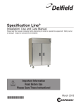
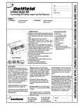
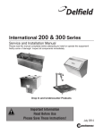
1
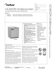
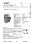
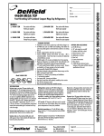
INSTALLATION &
OPERATION
MANUAL
Specification Line®
Please read this
manual completely
before attempting to
install or operate
this
equipment!
Notify carrier of
damage. Inspect all
components immediately. See page 6.
Delfield 980 S. Isabella Rd., Mt. Pleasant, MI 48858
(989) 773-7891 or (800) 733-8829 • Fax (989) 773-3210
www.delfield.com
October 2005
Delfield
IMPORTANT WARNING AND SAFETY INFORMATION
WARNING
Read this manual thoroughly before operating, installing, or performing maintenance
on the equipment.
FAILURE TO FOLLOW INSTRUCTIONS IN THIS MANUAL CAN CAUSE PROPERTY
DAMAGE, INJURY OR DEATH.
DO NOT STORE OR USE GASOLINE OR OTHER FLAMMABLE VAPORS OR LIQUIDS IN
THE VICINITY OF THIS OR ANY OTHER APPLIANCE.
UNLESS ALL COVER AND ACCESS PANELS ARE IN PLACE AND PROPERLY SECURED, DO NOT OPERATE THIS EQUIPMENT.
DAMP OR WET HANDS MAY STICK TO COLD SURFACES.
ALLOW HEATED EQUIPMENT TO COOL DOWN BEFORE ATTEMPTING TO CLEAN OR
SERVICE.
CAUTION
Observe the following:
•
•
•
•
•
•
2
Minimum clearances must be maintained.
Keep the equipment area free and clear of combustible material.
Allow adequate clearance for air openings.
Operate equipment only on the type of electricity indicated on the specification plate.
Unplug the unit before making any repairs.
Retain this manual for future reference.
Specification Line
Table of Contents
SAFETY PRECAUTIONS.................................................................... 2
INTRODUCTION ................................................................................. 5
General .......................................................................................... 5
Heating System ............................................................................. 5
Refrigeration System ..................................................................... 5
Freezer Refrigeration System ........................................................ 5
Dual Temperature Refrigeration/Freezer ....................................... 5
SERIAL NUMBER ............................................................................... 6
RECEIVING AND INSPECTING THE EQUIPMENT ........................... 6
SPECIFICATIONS .............................................................................. 7
INSTALLATION ................................................................................. 17
REACH-INS AND PASS-THRUS ...................................................... 17
Location ....................................................................................... 17
Inside Cabinet .............................................................................. 17
Outside Cabinet ........................................................................... 17
Leg and Caster Installation .......................................................... 17
Utility Base ................................................................................... 17
Leveling ....................................................................................... 18
Stabilizing..................................................................................... 18
Electrical Connection ................................................................... 18
3
Delfield
Table of Contents – Continued
ROLL-INS AND ROLL-THRUS ........................................................ 18
Location ................................................................................................. 18
Inside Cabinet .............................................................................. 18
Outside Cabinet ........................................................................... 18
Leveling ....................................................................................... 19
Stabilizing..................................................................................... 19
Electrical Connection ................................................................... 19
OPERATION INFORMATION ........................................................... 19
HEATED MODELS ............................................................................ 19
REFRIGERATION MODELS ............................................................. 20
OPTIONAL ERC CONTROL ............................................................. 23
OPTIONAL ERC CONTROL PROGRAMMING ................................ 24
TIMER CONTROL OPERATION ...................................................... 25
TIMER CONTROL PROGRAMMING ................................................ 25
AIROTRONICS TIMER OPERATION ............................................... 26
STANDARD LABOR GUIDELINES ................................................... 27
STANDARD TWO YEAR WARRANTY ............................................. 28
ADDITIONAL THREE YEAR WARRANTY........................................ 29
NOTES .............................................................................................. 30
4
Specification Line
INTRODUCTION
Refrigeration System
General
All components are mounted to the exterior cabinet
ceiling, outside the food zone and are assembled as onepiece and can be removed as one-piece. Environmentally friendly R404A refrigerant is used. The system has
the capability of maintaining between 27°F and 44°F in
heavy use food service operations. Refrigerant is metered using a highly responsive thermostatic expansion
valve. System is controlled using Delfield’s ACT-Advanced Control Technology electronic temperature control, which provides improved pull down times, reducing
compressor cycling and longer compressor life with
lower energy consumption. Control system uses adaptive defrost to assure evaporator coil is free of ice and
operating at optimum efficiency. Evaporator condensate
is eliminated using an energy efficient hot gas system.
Model numbers starting with the letters “SS” have a
stainless steel exterior and interior. Model numbers
starting with the letters “SA” have an aluminum interior
and a stainless steel exterior. Door gaskets are magnetic
and mount to the door, snapping in place and are
removable without tools. Keyed door lock is mounted in
the door next to the handle.
Doors can be removed from the cabinet without the use
of tools. Each door has two edge mount, self-closing,
cam lift style hinges.
Model Number
The following chart (see below) describes the model
number system used in this manual.
Heating System
Heating system cabinets are designed to maintain temperatures between 120°F and 200°F. Heating elements
are helical shaped, with tubular fins. A circulating fan
provides uniform airflow in the cabinet. The entire heating
system is mounted to the exterior of the cabinet ceiling,
outside the food zone. It is assembled as one piece and
can be removed as one piece. An adjustable electronic
thermostat controls temperature. The system ON/OFF
switch is located on the front exterior of the cabinet.
Freezer Refrigeration System
All components are mounted to the exterior cabinet ceiling,
outside the food zone and are assembled as one-piece and
can be removed as one-piece. Environmentally friendly
R404A refrigerant is used. The system has the capability
of maintaining between -5°F and 0°F in heavy use food
service operations. Refrigerant is metered using a highly
responsive thermostatic expansion valve. Evaporator defrost is automatic using a time initiated, time/temperature
terminated system with electric heaters. Evaporator condensate is eliminated using an energy efficient hot gas
system.
5
Delfield
Dual Temperature Refrigeration/Freezer
Each compartment has its own separate refrigeration system.
Condensing units are located on top of the cabinet, outside the
food zone, behind the removable upper shroud. Evaporator
coils are located inside the cabinet mounted to the interior
ceiling of each compartment. Defrost is automatic. Condensate travels down a tube in the cabinet sidewall to a receptacle
mounted to the exterior bottom of the cabinet where it evaporates with the aid of an electric heater. Each compartment’s
temperature is individually monitored and controlled. Two
exterior digital thermometers monitor temperature. Refrigerator compartment maintains temperature between 33°F and
41°F. Freezer compartment maintains temperature between
+5°F and -5°F. Refrigerant is metered using a highly responsive thermostatic expansion valve.
SERIAL NUMBER
Always have the serial number of your unit available
when calling for parts or service. The serial number is on
the identification plate that also includes the model
number. A typical identification plate is shown below. On
refrigeration and freezer unit the identification plate is
located inside the right most door (the only door on onedoor unit), near the top front corner of the right interior
wall. On heated units, the identification plate is located in
the shroud area on the right side panel. For parts and
services go to www.delfield.com.
6
RECEIVING AND INSPECTING
THE EQUIPMENT
Care should be taken during unloading so the equipment
is not damaged while being moved into the building.
1. Visually inspect the exterior of the package and
skid or container. Any damage should be noted
and reported to the delivering carrier immediately.
2. If damaged, open and inspect the contents with
the carrier.
3. In the event that the exterior is not damaged,
yet upon opening, there is concealed damage
to the equipment notify the carrier. Notification
should be made verbally as well as in written
form.
4. Request an inspection by the shipping company of the damaged equipment. This should
be done within 10 days from receipt of the
equipment.
5. Also inspect the heating package on heated
units and the compressor compartment housing and the refrigeration package on refrigerator and freezer units. Be sure lines are secure
and base is still intact.
7. Freight carriers can supply the necessary damage forms upon request.
8. Retain all shipping material until an inspection
has been made or waived.
Specification Line
SPECIFICATIONS
HEATED ROLL-THRU
MODEL
NUMBER
VOLTAGE
AMPS
SSHRT1-S, SAHRT1-S
120/208-240
9.0
SSHRT2-S, SAHRT2-S
120/208-240
SSHRT3-S, SAHRT3-S
STORAGE
CU. FT.
SHELVES
SQ. FT.
NO. OF
SHELVES
UNIT
H.P.
BTU/HR
CAB
LOAD
BTU/HR
SYSTEM
CAP
SHIP
WGT
NEMA
PLUG
38.58
N/A
N/A
N/A
N/A
N/A
504
N/A
16
79.74
N/A
N/A
N/A
N/A
N/A
806
N/A
120/208-240
17.8
120.90
N/A
N/A
N/A
N/A
N/A
940
N/A
SSHRT1-GS, SAHRT1-GS
120/208-240
9.0
38.58
N/A
N/A
N/A
N/A
N/A
519
N/A
SSHRT2-GS, SAHRT2-GS
120/208-240
16
79.74
N/A
N/A
N/A
N/A
N/A
836
N/A
SSHRT3-GS, SAHRT3-GS
120/208-240
17.8
120.90
N/A
N/A
N/A
N/A
N/A
985
N/A
BTU/HR
CAB
BTU/HR
SYSTEM
SHIP
WGT
NEMA
PLUG
LOAD
CAP
SOLID DOOR HOT FOOD CABINET REACH-IN
MODEL
NUMBER
VOLTAGE
AMPS
STORAGE
CU. FT.
SHELVES
SQ. FT.
NO. OF
SHELVES
UNIT
H.P.
SSH1-S, SSH1-SH,
SAH1I-S, SAH1-SH
120/208-240
9.0
24.96
12.81
3
N/A
N/A
N/A
420
N/A
SSH2-S, SSH2-SH,
SAH2-S, SAH2-SH
120/208-240
16.0
51.92
27.54
6
N/A
N/A
N/A
562
N/A
SSH3-S, SSH3-SH,
SAH3-S, SAH3-SH
120/208-240
17.8
78.89
42.47
9
N/A
N/A
N/A
782
N/A
SELF CONTAINED SOLID DOOR HEATED ROLL-IN
MODEL
NUMBER
VOLTAGE
AMPS
120/208-240
9.0
SSHRL2-S, SAHRL2-S,
120/208-240
SSHRL3-S, SAHRL3-S,
120/208-240
SSHRL1-S, SAHRL1-S,
STORAGE
CU. FT.
SHELVES
SQ. FT.
NO. OF
SHELVES
UNIT
H.P.
BTU/HR
CAB
LOAD
BTU/HR
SYSTEM
CAP
SHIP
WGT
NEMA
PLUG
36.15
12.81
N/A
N/A
N/A
N/A
459
N/A
12.2
74.72
12.81
N/A
N/A
N/A
N/A
704
N/A
10
113.28
12.81
N/A
N/A
N/A
N/A
1008
N/A
SELF CONTAINED GLASS DOOR HEATED ROLL-IN
MODEL
NUMBER
VOLTAGE
AMPS
SSHRL1-S, SAHRL1-S,
120/208-240
9.0
SSHRL2-S, SAHRL2-S,
120/208-240
SSHRL3-S, SAHRL3-S,
120/208-240
STORAGE
CU. FT.
SHELVES
SQ. FT.
NO. OF
SHELVES
UNIT
H.P.
BTU/HR
CAB
LOAD
BTU/HR
SYSTEM
CAP
SHIP
WGT
NEMA
PLUG
36.15
N/A
N/A
N/A
N/A
N/A
465
N/A
16.0
74.72
N/A
N/A
N/A
N/A
N/A
7284
N/A
17.8
113.28
N/A
N/A
N/A
N/A
N/A
1041
N/A
7
Delfield
SOLID DOOR NARROW HOT FOOD CABINET REACH-IN
MODEL
NUMBER
VOLTAGE
SSH2N-S SAH2N-S
115/208-240
AMPS
16
STORAGE
CU. FT.
51.92
SHELVES
SQ. FT.
27.54
NO. OF
SHELVES
6
UNIT
H.P.
BTU/HR
CAB
BTU/HR
SYSTEM
SHIP
WGT
NEMA
PLUG
LOAD
CAP
N/A
N/A
596
N/A
BTU/HR
CAB
BTU/HR
SYSTEM
SHIP
WGT
NEMA
PLUG
LOAD
CAP
N/A
GLASS DOOR HOT FOOD CABINET REACH-IN
MODEL
NUMBER
VOLTAGE
AMPS
STORAGE
CU. FT.
SHELVES
SQ. FT.
NO. OF
SHELVES
UNIT
H.P.
SSH1-G, SSH1-GH,
SAH1-G, SAH1-GH,
115/208-240
9.0
24.96
12.81
3
N/A
N/A
N/A
438
N/A
SSH2-G, SSH2-GH,
SAH2-G, SAH2-GH
115/208-240
16.0
51.92
27.54
6
N/A
N/A
N/A
569
N/A
SSH3-G, SSH3-GH,
SAH3G, SAH3GH
115/208-240
17.8
78.89
42.47
9
N/A
N/A
N/A
812
N/A
BTU/HR
CAB
BTU/HR
SYSTEM
SHIP
WGT
NEMA
PLUG
LOAD
CAP
SELF CONTAINED SOLID DOOR WINE CABINET REACH-IN
MODEL
NUMBER
VOLTAGE
AMPS
STORAGE
CU. FT.
SHELVES
SQ. FT.
NO. OF
SHELVES
UNIT
H.P.
SSW1-S, SSW1-SH,
SAW1-S, SAW1-SH
115
8.5
24.96
12.81
3
¼
758
2015
418
5-15P
SSW1-S, SSW1-SH,
SAW1-S, SAW1-SH
115
12.8
51.92
27.54
6
1/3
1374
2522
650
5-20P
SSW1-S, SSW1-SH,
SAW1-S, SAW1-SH
115
8.9
78.89
42.47
9
½
1971
3637
830
5-15P
SHIP
WGT
NEMA
PLUG
650
5-20P
SHIP
WGT
NEMA
PLUG
SELF CONTAINED SOLID DOOR READY THAW CABINET REACH-IN
MODEL
NUMBER
SST2-S, SST2-SH
VOLTAGE
115
AMPS
12.8
STORAGE
CU. FT.
51.92
SHELVES
SQ. FT.
27.54
NO. OF
SHELVES
6
UNIT
H.P.
1/3
BTU/HR
CAB
BTU/HR
SYSTEM
LOAD
CAP
1374
2522
SELF CONTAINED GLASS DOOR WINE CABINET REACH-IN
MODEL
NUMBER
8
VOLTAGE
AMPS
STORAGE
CU. FT.
SHELVES
SQ. FT.
NO. OF
SHELVES
UNIT
H.P.
BTU/HR
CAB
LOAD
BTU/HR
SYSTEM
CAP
SSW1-G, SSW1-GH,
SAW1-G, SAW1-GH
115
8.5
24.96
12.81
3
¼
758
2015
418
5-15P
SSW2-G, SSW2-GH,
SAW2-G, SAW2-GH
115
12.8
51.92
27.54
6
1/3
1374
2522
650
5-20P
SSW3-G, SSW3-GH,
SAW3-G, SAW3-GH
115
8.9
78.89
42.47
9
1/2
1971
3637
830
5-15P
Specification Line
SELF CONTAINED SHALLOW SOLID DOOR REACH-IN REFRIGERATOR
MODEL
NUMBER
VOLTAGE
AMPS
STORAGE
CU. FT.
SHELVES
SQ. FT.
NO. OF
SHELVES
UNIT
H.P.
BTU/HR
CAB
BTU/HR
SYSTEM
LOAD
CAP
SHIP
WGT
NEMA
PLUG
SSR1S-S, SSR1S-SH,
SAR1S-S, SAR1S-SH
115
8.5
24.96
12.81
3
¼
758
2015
418
5-15P
SSR2S-S, SSR2S-SH,
SAR2S-S, SAR2S-SH
115
12.8
51.92
27.54
6
1/3
1374
2522
650
5-20P
SSR3S-S, SSR3S-SH,
SAR3S-S, SAR3S-SH
115
8.9
78.89
42.47
9
½
1971
3637
830
5-15P
SELF CONTAINED SHALLOW HINGED GLASS DOOR REACH-IN REFRIGERATOR
MODEL
NUMBER
VOLTAGE
AMPS
STORAGE
CU. FT.
SHELVES
SQ. FT.
NO. OF
SHELVES
UNIT
H.P.
BTU/HR
CAB
BTU/HR
SYSTEM
LOAD
CAP
SHIP
WGT
NEMA
PLUG
SSR1S-G, SSR1S-GH,
SAR1S-G, SAR1S-GH
115
8.5
24.96
12.81
3
¼
758
2015
418
5-15P
SSR2S-G, SSR2S-GH,
SAR2S-G, SAR2S-GH
115
12.8
51.92
27.54
6
1/3
1374
2522
650
5-20P
SSR3S-G, SSR3S-GH,
SAR3S-G, SAR3S-GH
115
8.9
78.89
42.47
9
½
1971
3637
830
5-15P
SHIP
WGT
NEMA
PLUG
SELF CONTAINED SOLID DOOR ROLL-THRU REFRIGERATOR
MODEL
NUMBER
VOLTAGE
AMPS
STORAGE
CU. FT.
SHELVES
SQ. FT.
NO. OF
SHELVES
UNIT
H.P.
BTU/HR
CAB
BTU/HR
SYSTEM
LOAD
CAP
SSRRT1, SARRT1-S
115
10.3
38.58
N/A
N/A
½
1706
3120
494
5-15P
SSRRT2-S, SARRT2-S
115/208-230
10.1
79.74
N/A
N/A
¾
3263
69.20
736
N/A
SSRRT3-S, SARRT3-S
115/208-230
11.3
120.9
N/A
N/A
¾
4815
7569
1056
N/A
SELF CONTAINED GLASS DOOR ROLL-IN REFRIGERATOR
MODEL
NUMBER
VOLTAGE
AMPS
STORAGE
CU. FT.
SHELVES
SQ. FT.
NO. OF
SHELVES
UNIT
H.P.
BTU/HR
CAB
BTU/HR
SYSTEM
LOAD
CAP
SHIP
WGT
NEMA
PLUG
SSRRL1-G, SARRL1-G
115
9.0
36.15
N/A
N/A
1/3
1331
2614
487
5-15P
SSRRL2-G, SARRL2-G
115
12.2
74.72
N/A
N/A
½
2512
4046
798
5-15P
SSRRL3-G, SARRL3-G
115/208-230
10
113.28
N/A
N/A
¾
3687
7569
1152
N/A
9
Delfield
SELF CONTAINED HINGED GLASS DOOR PASS-THRU REFRIGERATOR
MODEL
NUMBER
VOLTAGE
AMPS
STORAGE
CU. FT.
SHELVES
SQ. FT.
NO. OF
SHELVES
UNIT
H.P.
BTU/HR
CAB
BTU/HR
SYSTEM
LOAD
CAP
SHIP
WGT
NEMA
PLUG
SSRPT1-G, SSRPT1-GH,
SARPT1-G, SARPT-GH
115
12.8
26.64
12.81
3
1/3
1537
2614
476
5/20P
SSRPT2-G, SSRPT2-GH,
SARPT2-G, SARPT2-GH
115
11.2
55.42
27.54
6
½
3001
4096
740
5-15P
SSRPT3-G, SSRPT3-GH,
SARPT3-G, SARPT3-GH
115/208-230
12.4
84.19
42.27
9
¾
4451
7569
1032
14-20P
SELF CONTAINED SOLID DOOR ROLL-IN REFRIGERATOR
MODEL
NUMBER
VOLTAGE
AMPS
STORAGE
CU. FT.
SHELVES
SQ. FT.
NO. OF
SHELVES
UNIT
H.P.
BTU/HR
CAB
BTU/HR
SYSTEM
LOAD
CAP
SHIP
WGT
NEMA
PLUG
SSRRL1-S, SARRL1-S
115
9.0
36.15
N/A
N/A
1/3
1207
2354
476
5-15P
SSRRL2-S, SARRL2-S
115
12.2
74.72
N/A
N/A
½
2221
3637
768
5-15P
SSRRL3-S, SARRL3-S
115/208-230
10
113.28
N/A
N/A
¾
3229
6744
1044
N/A
SELF CONTAINED SOLID DOOR REACH-IN REFRIGERATOR
MODEL
NUMBER
VOLTAGE
AMPS
STORAGE
CU. FT.
SHELVES
SQ. FT.
NO. OF
SHELVES
UNIT
H.P.
BTU/HR
CAB
BTU/HR
SYSTEM
LOAD
CAP
SHIP
WGT
NEMA
PLUG
SSR1-S, SSR1-SH,
SAR1-S, SAR1-SH
115
8.5
24.96
12.81
3
¼
758
2015
418
5-15P
SSR2-S, SSR2-SH,
SAR2-S, SAR2-SH
115
12.8
51.92
27.54
6
1/3
1374
2522
650
5-20P
SSR3-S, SSR3-SH,
SAR3-S, SAR3-SH
115
8.9
78.89
42.47
9
½
1971
3637
830
5-15P
SHIP
WGT
NEMA
PLUG
SELF CONTAINED SHALLOW SOLID DOOR PASS-THRU REFRIGERATOR
MODEL
NUMBER
VOLTAGE
AMPS
STORAGE
CU. FT.
SHELVES
SQ. FT.
NO. OF
SHELVES
UNIT
H.P.
BTU/HR
CAB
BTU/HR
SYSTEM
LOAD
CAP
SSRPT1S, SARPT1S
115
12.8
26.64
12.81
3
1/3
968
2354
455
5-20P
SSRPT12S, SARPT2SS
115
11.2
55.42
27.54
6
½
1843
3637
700
5-15P
10
Specification Line
SELF CONTAINED NARROW HINGED GLASS DOOR REACH-IN REFRIGERATOR
MODEL
NUMBER
VOLTAGE
AMPS
STORAGE
CU. FT.
SHELVES
SQ. FT.
NO. OF
SHELVES
UNIT
H.P.
BTU/HR
CAB
BTU/HR
SYSTEM
LOAD
CAP
SHIP
WGT
NEMA
PLUG
SSR1N-G, SSR1N-GH,
SAR1N-G, SAR1N-GH
115
8.5
20.97
10.59
3
¼
713
2015
398
5-15P
SSR2N-G, SSR2N-GH,
SAR21N-G, SAR21N-GH
115
12.8
43.94
23.10
6
1/3
1285
2522
856
5-20P
SHIP
WGT
NEMA
PLUG
SELF CONTAINED SOLID DOOR PASS-THRU REFRIGERATOR
MODEL
NUMBER
VOLTAGE
AMPS
STORAGE
CU. FT.
SHELVES
SQ. FT.
NO. OF
SHELVES
UNIT
H.P.
BTU/HR
CAB
BTU/HR
SYSTEM
LOAD
CAP
SSRPT1, SARPTS
115
8.5
24.96
12.81
3
¼
758
2015
418
5-15P
SSRPT2, SARPT2
115
12.8
51.92
27.54
6
1/3
1374
2522
650
5-20P
SSRPT3, SARPT3
115
8.9
78.89
42.47
9
½
1971
3637
830
5-15P
SHIP
WGT
NEMA
PLUG
SELF CONTAINED SOLID DOOR PASS-THRU REFRIGERATOR
MODEL
NUMBER
VOLTAGE
AMPS
STORAGE
CU. FT.
SHELVES
SQ. FT.
NO. OF
SHELVES
UNIT
H.P.
BTU/HR
CAB
BTU/HR
SYSTEM
LOAD
CAP
SSR1N-S, SSR1N-SH,
SAR1N-S, SAR1N-SH
115
8.5
24.96
12.81
3
¼
758
2015
418
5-15P
SSR2N-SG, SSR2N-SH,
SAR21N-S, SAR21N-SH
115
12.8
51.92
27.54
6
1/3
1374
2522
650
5-20P
SHIP
WGT
NEMA
PLUG
SELF CONTAINED HINGED GLASS DOOR REACH-IN REFRIGERATOR
MODEL
NUMBER
VOLTAGE
AMPS
STORAGE
CU. FT.
SHELVES
SQ. FT.
NO. OF
SHELVES
UNIT
H.P.
BTU/HR
CAB
BTU/HR
SYSTEM
LOAD
CAP
SSR1-G, SSR1-GH,
SAR1-G, SAR1-GH
115
8.5
24.96
12.81
3
¼
758
2015
418
5-15P
SSR2-G, SSR2-GH,
SAR2-G, SAR2-GH
115
12.8
51.92
27.54
6
1/3
1374
2522
650
5-20P
SSR3-G, SSR3-GH,
SAR3-G, SAR3-GH
115
8.9
78.89
42.47
9
½
1971
3637
830
5-15P
11
Delfield
SELF CONTAINED SOLID DOOR ROLL-IN REFRIGERATOR
MODEL
NUMBER
VOLTAGE
AMPS
STORAGE
CU. FT.
SHELVES
SQ. FT.
NO. OF
SHELVES
UNIT
H.P.
BTU/HR
CAB
BTU/HR
SYSTEM
LOAD
CAP
SHIP
WGT
NEMA
PLUG
SSR1-S, SSR1-SH,
SAR1-S, SAR1-SH
115
8.5
24.96
12.81
3
¼
758
2015
418
5-15P
SSR2-S, SSR2-SH,
SAR2-S, SAR2-SH
115
12.8
51.92
27.54
6
1/3
1374
2522
650
5-20P
SSR3-S, SSR3-SH,
SAR3-S, SAR3-SH
115
8.9
78.89
42.47
9
½
1971
3637
830
5-15P
SHIP
WGT
NEMA
PLUG
SELF CONTAINED FISH DRAWER REACH-IN REFRIGERATOR
MODEL
NUMBER
VOLTAGE
AMPS
STORAGE
CU. FT.
SHELVES
SQ. FT.
NO. OF
SHELVES
UNIT
H.P.
BTU/HR
CAB
BTU/HR
SYSTEM
LOAD
CAP
SSRFF1
115
8.5
24.96
N/A
N/A
¼
758
2015
418
5-15P
SSRFF2
115
12.8
51.92
N/A
N/A
1/3
1374
2522
650
5-20P
SHIP
WGT
NEMA
PLUG
670
5-15P
SHIP
WGT
NEMA
PLUG
670
5-15P
SHIP
WGT
NEMA
PLUG
SELF CONTAINED SLIDING DOOR SHALLOW REACH-IN REFRIGERATOR
MODEL
NUMBER
SSR2S-SL, SAR2S-SL
VOLTAGE
115
AMPS
11.2
STORAGE
CU. FT.
51.92
SHELVES
SQ. FT.
27.54
NO. OF
SHELVES
6
UNIT
H.P.
1/3
BTU/HR
CAB
BTU/HR
SYSTEM
LOAD
CAP
1853
2801
SELF CONTAINED SLIDING DOOR REACH-IN REFRIGERATOR
MODEL
NUMBER
SSR2-SL, SAR2-SL
VOLTAGE
115
AMPS
11.2
STORAGE
CU. FT.
51.92
SHELVES
SQ. FT.
27.54
NO. OF
SHELVES
6
UNIT
H.P.
1/3
BTU/HR
CAB
BTU/HR
SYSTEM
LOAD
CAP
1853
2801
SELF CONTAINED SHALLOW SOLID DOOR REACH-IN FREEZER
MODEL
NUMBER
VOLTAGE
AMPS
STORAGE
CU. FT.
SHELVES
SQ. FT.
NO. OF
SHELVES
UNIT
H.P.
BTU/HR
CAB
BTU/HR
SYSTEM
LOAD
CAP
SSF1S-S, SSF1S-SH,
SAF1S-S, SAF1S-SH
115
11.4
18.25
8.98
3
½
1102
16.29
406
5-15P
SSF2S-S, SSF2S-SH,
SAF2S-S, SAF2S-SH
115
16
37.96
19.04
6
¾
2064
3326
676
5-20P
SSF3S-S, SSF3S-SH,
SAF3S-S, SAF3S-SH
115
11.4
57.67
29.10
9
1
2995
4253
909
14-20P
12
Specification Line
SELF CONTAINED SOLID DOOR ROLL-IN FREEZER
MODEL
NUMBER
VOLTAGE
AMPS
STORAGE
CU. FT.
SHELVES
SQ. FT.
NO. OF
SHELVES
UNIT
H.P.
BTU/HR
CAB
BTU/HR
SYSTEM
LOAD
CAP
SHIP
WGT
NEMA
PLUG
SSFRL1-S, SAFRL1-S
115
13.7
36.15
N/A
N/A
½
1516
2094
497
5-20P
SSFRL1-S, SAFRL1-S
115/208-230
9.3
74.72
N/A
N/A
1
2714
3494
824
N/A
SSFRL1-S, SAFRL1-S
115/208-230
11.8
113.28
N/A
N/A
1½
3901
5394
1128
N/A
SELF CONTAINED SOLID DOOR NARROW REACH-IN FREEZER
MODEL
NUMBER
VOLTAGE
AMPS
STORAGE
CU. FT.
SHELVES
SQ. FT.
NO. OF
SHELVES
UNIT
H.P.
BTU/HR
CAB
BTU/HR
SYSTEM
LOAD
CAP
SHIP
WGT
NEMA
PLUG
SSF1N-S, SSF1N-SH,
SAF1N-S, SAF1N-SH
115
11.4
20.97
10.59
3
½
1166
1629
408
5-15P
SSF2N-SG, SSF2N-SH,
SAF21N-S, SAFR21N-SH
115
16
43.94
23.10
6
¾
2101
3326
680
5-20P
SELF CONTAINED SOLID DOOR TWO SECTION DUAL TEMP
REFRIGERATOR/FREEZER PASS-THRU
MODEL
NUMBER
DESCRIPTION
VOLTAGE
AMPS
STORAGE
CU. FT.
SHELVES
SQ. FT.
NO. OF
SHELVES
UNIT
H.P.
BTU/HR
CAB
LOAD
BTU/HR
SYSTEM
CAP
SHIP
WEIGHT
NEMA
PLUG
SSDRLPT2,
SADRLPT2
LEFT DR REF
RIGHT DR FRZ
115
115
8.5
11.4
24.96
24.96
12.81
12.81
3
3
¼
½
758
1239
2015
1868
730
730
5-15P
5-15P
SSDFLPT2,
SADFLPT2
LEFT DR FRZ
RIGHT DR REF
115
115
11.4
8.5
24.96
24.96
12.81
12.81
6
6
½
¼
1239
758
1868
2015
730
730
5-15P
5-15P
GLASS DOOR SINGLE SECTION DUAL TEMP REFRIGERATOR/FREEZER REACH-INS
MODEL
NUMBER
VOLTAGE
AMPS
STORAGE
CU. FT.
NO. OF
SHELVES
UNIT
H.P.
BTU/HR
CAB
LOAD
BTU/HR
SYSTEM
CAP
SHIP
WEIGHT
NEMA
PLUG
545 LBS. TOTAL
5-20P
545 LBS. TOTAL
5-20P
SSDTR1-GH/ SADTR1-GH
Refrigerator
115/60/1
12.19
2
1/5
550
1725
12.19
2
1/3
910
1380
12.19
2
1/3
910
1380
12.19
2
1/5
550
1725
14 TOTAL
Freezer
115/60/1
SSDBR1-GH/ SADBR1-GH
Freezer
115/60/1
14 TOTAL
Refrigerator
115/60/1
13
Delfield
SOLID DOOR SINGLE SECTION DUAL TEMP REFRIGERATOR/FREEZER
PASS-THRU UNITS
MODEL
NUMBER
VOLTAGE
AMPS
STORAGE
CU. FT.
NO. OF
SHELVES
UNIT
H.P.
BTU/HR
CAB
LOAD
BTU/HR
SYSTEM
CAP
SHIP
WEIGHT
NEMA
PLUG
545 LBS. TOTAL
5-20P
545 LBS. TOTAL
5-20P
BTU/HR
CAB
BTU/HR
SYSTEM
SHIP
WGT
NEMA
PLUG
LOAD
CAP
SSDTPT1-SH/ SADTPT1-SH
Refrigerator
115/60/1
12.19
2
1/5
563
1543
Freezer
115/60/1
12.19
2
1/3
921
1260
Freezer
115/60/1
12.19
2
1/3
921
1260
Refrigerator
115/60/1
12.19
2
1/5
563
1543
14 TOTAL
SSDBT1-SH/ SADPT1-SH
14 TOTAL
SELF CONTAINED SOLID DOOR PASS-THRU FREEZER
MODEL
NUMBER
VOLTAGE
AMPS
STORAGE
CU. FT.
SHELVES
SQ. FT.
NO. OF
SHELVES
UNIT
H.P.
SSFPT1, SAFPT1
115
13.7
26.64
12.81
3
½
1583
2467
672
5-20P
SSFPT2, SAFPT2
115/208-230
7.0
55.42
27.54
6
1
3013
3497
1001
14-20P
SSFPT3, SAFPT3
115/208-230
10.0
84.19
42.27
9
1½
4412
5185
1268
14-20P
SELF CONTAINED SOLID DOOR TWO SECTION DUAL TEMP
REFRIGERATOR/FREEZER REACH-INS
MODEL
NUMBER
SSDRL1, SADRL1
SSDFL2, SADFL2
14
DESCRIPTION
VOLTAGE
LEFT DR REF
115
RIGHT DR FRZ
AMPS
STORAGE
CU. FT.
SHELVES
SQ. FT.
NO. OF
SHELVES
UNIT
H.P.
BTU/HR
CAB
LOAD
BTU/HR
SYSTEM
CAP
SHIP
WEIGHT
NEMA
PLUG
8.5
24.96
12.81
3
¼
758
2015
730
5-15P
115
11.4
24.96
12.81
3
½
1239
1868
730
5-15P
LEFT DR FRZ
115
11.4
24.96
12.81
6
½
1239
1868
730
5-15P
RIGHT DR REF
115
8.5
24.96
12.81
6
¼
758
2015
730
5-15P
Specification Line
SOLID DOOR SINGLE SECTION DUAL TEMP REFRIGERATOR/FREEZER REACH-INS
MODEL
NUMBER
VOLTAGE
AMPS
STORAGE
CU. FT.
NO. OF
SHELVES
UNIT
H.P.
BTU/HR
CAB
LOAD
BTU/HR
SYSTEM
CAP
SHIP
WEIGHT
NEMA
PLUG
545 LBS. TOTAL
5-20P
545 LBS. TOTAL
5-20P
SDTR1-SH/ SADTR1-SH
Refrigerator
115/60/1
11.52
2
1/5
455
1543
Freezer
115/60/1
11.52
2
1/3
744
1260
Freezer
115/60/1
11.52
2
1/3
744
1260
Refrigerator
115/60/1
11.52
2
1/5
455
1543
14 TOTAL
SDBR1-SH/ SADBR1-SH
14 TOTAL
SELF CONTAINED HINGED GLASS DOOR REACH-IN FREEZER
MODEL
NUMBER
VOLTAGE
AMPS
STORAGE
CU. FT.
SHELVES
SQ. FT.
NO. OF
SHELVES
UNIT
H.P.
BTU/HR
CAB
BTU/HR
SYSTEM
LOAD
CAP
SHIP
WGT
NEMA
PLUG
SSF1-G, SSF1-GH,
SAF1-G, SAF1-GH
115
13.7
24.96
12.81
3
½
1605
2300
450
5-20P
SSF2-G, SSF2-GH,
SAF2-G, SAF2-GH
115
9.3
51.92
27.54
6
1
3009
3843
730
14-20P
SSF3-G, SSF3-GH,
SAF3-G, SAF31-GH
115
10.0
78.89
42.47
9
1½
4386
5940
990
14-20P
SELF CONTAINED SOLID DOOR REACH-IN FREEZER
MODEL
NUMBER
VOLTAGE
AMPS
STORAGE
CU. FT.
SHELVES
SQ. FT.
NO. OF
SHELVES
UNIT
H.P.
BTU/HR
CAB
BTU/HR
SYSTEM
LOAD
CAP
SHIP
WGT
NEMA
PLUG
SSF1-S, SSF1-SH,
SAF1-S, SAF1-SH
115
11.4
24.96
12.81
3
½
1239
1868
440
5-15P
SSF2-S, SSF2-SH,
SAF2-S, SAF2-SH
115
16
51.92
27.54
6
¾
2247
3326
710
5-20P
SSF3-S, SSF3-SH,
SAF3-S, SAF31-SH
115/208-230
11.4
78.89
42.47
9
1
3222
4136
960
14-20P
15
Delfield
SELF CONTAINED SOLID DOOR CONVERT-A-TEMP REACH-IN
MODEL
NUMBER
VOLTAGE
AMPS
STORAGE
CU. FT.
SHELVES
SQ. FT.
NO. OF
SHELVES
UNIT
H.P.
BTU/HR
CAB
BTU/HR
SYSTEM
LOAD
CAP
SHIP
WGT
NEMA
PLUG
SSR1-S, SAR1-S
115
11.4
24.96
12.81
3
½
1239
1868
440
5-15P
SSR2-S, SAR2-S
115
16
51.92
27.54
6
¾
2247
3326
710
5-20P
GLASS DOOR SINGLE SECTION DUAL TEMP REFRIGERATOR/FREEZER
PASS-THRU UNITS
MODEL
NUMBER
VOLTAGE
AMPS
STORAGE
CU. FT.
NO. OF
SHELVES
UNIT
H.P.
BTU/HR
CAB
LOAD
BTU/HR
SYSTEM
CAP
12.19
2
1/5
830
1725
SHIP
WEIGHT
NEMA
PLUG
545 LBS. TOTAL
5-20P
545 LBS. TOTAL
5-20P
SSDTPT1-GH/ SADTPT1-GH
Refrigerator
115/60/1
Freezer
115/60/1
12.19
2
1/3
1329
1380
Freezer
115/60/1
12.19
2
1/3
1329
1380
Refrigerator
115/60/1
12.19
2
1/5
830
1725
14 TOTAL
SSDBPT1-GH/ SADBPT1-GH
14 TOTAL
16
Specification Line
INSTALLATION
REACH-INS AND PASS-THRUS
Location
Cabinets represented in this manual are intended for indoor
use only. Be sure the location chosen has a floor strong
enough to support the total weight of the cabinet, 1000 lbs.
per door section. Reinforce the floor if necessary to provide
for maximum loading. For the most efficient operation, be
sure to provide good air circulation inside and out. The
location should be selected so that the power cord can be
connected without any extensions.
Inside Unit
Take care not to block airflow to the fans or heating
elements and allow space along the front, back and
sides.
Outside Unit
Be sure that the unit has access to ample air; avoid hot
corners and locations near stoves and ovens. Provide a
minimum clearance of 12” (30.5 cm) above the unit that
is open to the front.
Leg and Caster Installation
WARNING:
Some cabinets may weigh over 1000 lbs (450 kg).
Use a lifting device capable of supporting the unit
when removing skid or installing legs or casters.
To install the legs, refer to Figure 1 and proceed as
follows:
Figure 1. Leg or Caster Installation
To install the utility base, refer to Figure 2 and proceed as
follows:
1. Remove unit from skid.
2. Raise unit to access leg/caster mounting holes
on bottom of unit.
3. Attach the utility base to bottom of cabinet
using the leg/caster mounting screws.
1. Remove unit from skid.
2. Raise unit to access leg/caster mounting holes
on bottom of unit.
3. Attach the legs with the four hex head bolts.
To install the casters, refer to Figure 1 and proceed as
follows:
1. Remove unit from skid.
2. Raise unit to access leg/caster mounting holes
on bottom of unit.
3. Attach the casters with the four hex head bolts.
Utility Base
WARNING:
Some cabinets may weigh over 1000 lbs (450 kg).
Use a lifting device capable of supporting the unit
when removing skid or installing legs or casters.
Figure 2. Utility Base Installation
Leveling
After the cabinet has been placed in the desired location,
cabinets with legs must be leveled. Level units from front
to back and from side to side. Leveling will insure proper
door operation and removal of condensate. Cabinets
with casters must have the caster brake set so the
cabinet cannot move.
17
Delfield
Stabilizing
It is very important that all legs are properly adjusted to
keep the cabinet level, evenly distribute the weight and to
make sure the unit will not rock, lean or be unstable.
Electrical Connection
DANGER
Refer to the amperage data list in the SPECIFICATIONS or the serial tag data and your local code or
the National Electrical Code to be sure the unit is
connected to the proper power source. A protected
circuit of the correct voltage and amperage must be
run for connection of the supply cord or permanent
connection to the unit. The power must be turned
off and disconnected whenever performing maintenance or repair functions.
CAUTION
Permanently connected units must be connected in
accordance with NEC Article 422 Appliances, C-Disconnecting means. It is the responsibility of the end user
to provide the disconnect means to satisfy the authority
having jurisdiction.
The power cords supplied with this equipment are threepronged plugs and must be connected to a three-pronged
wall outlet for proper grounding. Do not use an adapter
to connect to a two-pronged outlet. The three prongedoutlet provides a ground connection which must be
used to prevent a shock hazard.
Figure 3. Plug Configurations
to provide for maximum loading. For the most efficient
operation, be sure to provide good air circulation inside
and out. The location should be selected so that the
power cord can be connected without any extensions.
Inside Cabinet
Take care not to block airflow to the fans or heating
elements and allow space along the front, back and sides.
Outside Cabinet
Be sure that the unit has access to ample air; avoid hot
corners and locations near stoves and ovens. Provide a
minimum clearance of 12" (30.5 cm) above the unit that
is open to the front.
CAUTION
Have the wall outlet checked by a qualified electrician to
be sure a proper ground is present and that the outlet
provides the correct voltage and required amperage to
match the rating plate.
Any power cord that is frayed or damaged should be
replaced. When disconnecting the unit from the power
source, do not pull on the wire. Firmly grip the plug and
remove from outlet.
Door Removal
If the doors need to be removed during installation,
proceed as follows:
1. Remove top hinge cover from hinge as shown
in Figure 4.
2. Remove door from unit by lifting door up a few
inches and pulling away from unit.
The plugs shown in Figure 3 are used on the various models.
ROLL-INS AND ROLL-THRU MODELS
Door
hinge
cover
Location
Cabinets represented in this manual are intended for
indoor use only. Be sure the location chosen has a floor
strong enough to support the total weight of the cabinet.
Allow for a total load of approximately 1000 pounds
(450 kg) per door section. Reinforce the floor if necessary
18
Figure 4. Door Hinge Cover
Specification Line
Leveling
After the cabinet has been placed in the desired location,
cabinets with legs must be leveled. Level units from front
to back and from side to side. Leveling will insure proper
door operation and removal of condensate. Cabinets with
casters must have the caster brake set so the cabinet
cannot move.
Stabilizing
It is very important that all legs are properly adjusted to
keep the unit level, to evenly distribute the weight and to
make sure the unit will not rock, lean or be unstable.
Electrical Connection
DANGER
Refer to the amperage data list in the SPECIFICATIONS or the serial tag data and your local code or
the National Electrical Code to be sure the unit is
connected to the proper power source. A protected
circuit of the correct voltage and amperage must be
run for connection of the supply cord or permanent
connection to the unit. The power must be turned
off and disconnected whenever performing maintenance or repair functions.
CAUTION
Permanently connected units must be connected in
accordance with NEC Article 422 Appliances, C-Disconnecting means. It is the responsibility of the end user
to provide the disconnect means to satisfy the authority
having jurisdiction.
OPERATION
HEATED CABINETS
The Heated units have a POWER ON/OFF switch located behind the flip up shroud at the front top of the unit
for controlling power to the unit and an electronic thermostat for setting the temperature. A circulating fan provides uniform airflow in the cabinet. Refer to Figure 6 for
location of operating controls and proceed as follows:
1. Check that unit is properly connected to the
power source.
2. Raise the shroud to access the controls.
3. Set the Main POWER ON/OFF switch, to the
ON position.
4. Adjust the electronic thermostat to the desired
temperature.
5. Allow unit to warm-up before use.
DANGER
The unit surface is very hot! Avoid direct contact
with skin; use appropriate protective apparel, such
as gloves.
6. Turn the unit off by setting the POWER ON/
OFF switch to the OFF position
7. After use, allow unit to cool down.
8. Clean equipment as discussed in the MAINTENANCE section of this manual.
The power cords supplied with this equipment are threepronged plugs and must be connected to a three-pronged
wall outlet for proper grounding. Do not use an adapter
to connect to a two-pronged outlet. The three prongedoutlet provides a ground connectio0n which must be
used to prevent a shock hazard.
CAUTION
Have the wall outlet check by a qualified electrician to be
sure a proper ground is present and that the outlet
provides the correct voltage and required amperage to
match the rating plate.
Any power cord that is frayed or damaged should be
replaced. When disconnecting the unit from the power
source, do not pull on the wire. Firmly grip the plug and
remove from outlet.
The plugs shown in Figure 5 are used on the various
models.
Figure 5. Plug Configurations
19
Delfield
Operating Controls
REFRIGERATED THAW CABINETS
REFRIGERATED WINE CABINETS
Refrigerated thaw cabinet units have a POWER ON/OFF
switch located on the front of the unit for controlling power
to the unit and a Delfield’s ACT-Advanced Control Technology electronic temperature control for setting the temperature. The temperature control holds the temperature between 27°F and 44°F and provides improved pull down
times, reducing compressor cycling and longer compressor life with low energy consumption. Refrigerant is metered using a highly responsive thermostatic expansion
valve. The control system uses adaptive defrost to assure
evaporator coil is free of ice and operating at optimum
efficiency. Evaporator condensate is eliminated using an
energy efficient hot gas system. An exterior digital thermostat monitors cabinet temperature. Thawing is aided by
mullion mounted heater and fan system. To operate the
refrigerated thaw cabinet unit, refer to Figure 6 for location
of operating controls and proceed as follows:
Refrigerated wine cabinet units have a POWER ON/OFF
switch located on the front of the unit for controlling power
to the unit and a Delfield’s ACT-Advanced Control Technology electronic temperature control for setting the
temperature. The temperature control holds the temperature between 50°F and 60°F and provides improved
pull down times, reducing compressor cycling and longer
compressor life with low energy consumption. Refrigerant is metered using a highly responsive thermostatic
expansion valve. The control system uses adaptive
defrost to assure evaporator coil is free of ice and
operating at optimum efficiency. Evaporator condensate
is eliminated using an energy efficient hot gas system. An
exterior digital thermostat monitors cabinet temperature.
To operate the refrigerated wine cabinet unit, refer to
Figure 6 for location of operating controls and proceed as
follows:
1. Check that unit is properly connected to the
power source.
2. Raise the shroud to access the controls.
3. Set the main POWER ON/OFF switch to the
ON position.
4. Adjust the electronic temperature control to the
desired temperature.
5. Turn the unit off by placing the POWER ON/
OFF switch in the OFF position.
1. Check that unit is properly connected to the
power source.
2. Raise the shroud to access the controls.
3. Set the main POWER ON/OFF switch, to the
ON position
4. Adjust the electronic temperature control to the
desired temperature.
5. Turn the unit off by placing the POWER ON/
OFF switch in the OFF position.
6. Clean equipment as discussed in the maintenance section of this manual.
6. Clean equipment as discussed in the maintenance section of this manual.
Shroud (lift to access controls)
Operating controls (behind shroud)
Digital thermometer
Figure 6. Operating Controls and Indicator Location
20
Specification Line
REFRIGERATED CABINETS
Refrigerated cabinet units have a POWER ON/OFF
switch located on the front of the unit for controlling power
to the unit and a Delfield’s ACT-Advanced Control Technology electronic temperature control for setting the
temperature. The temperature control holds the temperature between 27°F and 44°F and provides improved
pull down times, reducing compressor cycling and longer
compressor life with low energy consumption. Refrigerant is metered using a highly responsive thermostatic
expansion valve. The control system uses adaptive
defrost to assure evaporator coil is free of ice and
operating at optimum efficiency. Evaporator condensate
is eliminated using an energy efficient hot gas system. An
exterior digital thermostat monitors cabinet temperature.
To operate the refrigerated cabinet unit, refer to Figure 6
for location of operating controls and proceed as follows:
1. Check that cabinet is properly connected to the
power source.
2. Raise the shroud to access the controls.
3. Set the main POWER ON/OFF switch, to the
ON position.
4. Adjust the electronic temperature control to the
desired temperature.
5. Turn the unit off by placing the POWER ON/
OFF switch in the OFF position.
6. Clean equipment as discussed in the maintenance section of this manual.
FREEZER CABINETS
Freezer cabinet units have a POWER ON/OFF switch
located on the front of the unit for controlling power to the
unit. Refrigerant is metered using a highly responsive
thermostatic expansion valve. The thermostatic expansion valve holds the temperature between -5°F and 0°F.
Refrigerant is metered using a highly responsive thermostatic expansion valve. Evaporator defrost is automatic
using a time initiated, time/temperature terminated system with electric heaters. Evaporator condensate is
eliminated using an energy efficient hot gas system. An
exterior digital thermometer monitors cabinet temperature. To operate the Freezer cabinet unit, refer to Figure
6 for location of operating controls and proceed as
follows:
1. Check that unit is properly connected to the
power source.
2. Raise the shroud to access the controls.
3. Set the main POWER ON/OFF switch, to the
ON position.
4. Adjust the time/temperature control to the desired temperature and time.
5. Turn the cabinet off by placing the POWER
ON/OFF switch in the OFF position.
6. Clean equipment as discussed in the maintenance section of this manual.
REFRIGERATOR/FREEZER CABINET
These units combine both a refrigerator compartment
and a freezer compartment in the same cabinet. Each
compartment has its own separate refrigeration unit. A
master POWER ON/OFF switch controls power to both
compartments.
Refrigeration Compartment
The refrigeration compartment uses a Delfield’s ACTAdvanced Control Technology electronic temperature
control for setting the temperature. The temperature
control holds the temperature between 27°F and 44°F
and provides improved pull down times, reducing compressor cycling and longer compressor life with low
energy consumption. Refrigerant is metered using a
highly responsive thermostatic expansion valve. An exterior digital thermostat monitors cabinet temperature.
To operate the refrigerator compartment, Refer to Figure
6 for location of operating controls and proceed as
follows:
1. Check that unit is properly connected to the
power source.
2. Raise the shroud to access the controls.
3. Set the main POWER ON/OFF switch, to the
ON position.
4. Adjust the electronic temperature control to the
desired temperature.
5. Turn the unit off by placing the POWER ON/
OFF switch in the OFF position.
6. Clean equipment as discussed in the maintenance section of this manual.
Freezer Compartment
Refrigerant is metered using a highly responsive thermostatic expansion valve. The thermostatic expansion valve
holds the temperature between -5°F and 0°F. Evaporator
defrost is automatic using a time initiated, time/temperature terminated system with electric heaters. Evaporator
condensate is eliminated using an energy efficient hot
gas system. An exterior digital thermometer monitors
cabinet temperature. To operate the Freezer compartment, refer to Figure 6 for location of operating controls
and proceed as follows:
1. Check that unit is properly connected to the
power source.
2. Set the main POWER ON/OFF switch, to the
ON position.
21
Delfield
3. Adjust the time/temperature control for the
freezer to the desired temperature and time
settings.
4. Set the temperature control for the desired temperature
5. Turn the unit off by placing the POWER ON/
OFF switch in the OFF position.
6. Clean equipment as discussed in the maintenance section of this manual.
CONVERT-A-TEMP
This unit can be used as either a refrigerator or a freezer.
A key switch located behind the hinged upper shroud
performs conversion. A master POWER ON/OFF switch
controls power to the unit.
In the refrigeration mode the temperature is held between 27°F and 44°F. In the freezer mode the temperature is held between -5°F and 0°F. Refrigerant is metered
using a highly responsive thermostatic expansion valve.
Evaporator defrost is automatic off cycle in refrigeration
mode and a time initiated, time/temperature terminated
system with electric heaters in the freezer mode. Evaporator condensate is eliminated using an energy efficient
hot gas system. An exterior digital thermometer monitors
cabinet temperature. To operate the Convert-A-Temp
cabinet, refer to Figure 6 for location of operating controls
and proceed as follows:
1. Check that unit is properly connected to the
power source.
2. Set the main POWER ON/OFF switch, to the
ON position.
3. Using the key switch select either the refrigerator or freezer mode.
4. Adjust the electronic temperature control to the
desired temperature.
5. Turn the unit off by placing the POWER ON/
OFF switch in the OFF position.
6. Clean equipment as discussed in the maintenance section of this manual.
MAINTENANCE
Stainless Steel Care and Cleaning
To prevent discoloration of rust on stainless steel several
important steps need to be taken. First, we need to
understand the properties of stainless steel. Stainless
steel contains 70-80% iron which will rust. It also contains
12-30% chromium, which forms an invisible passive film
over the steels surface, which acts as a shield against
corrosion. As long as the protective layer is intact, the
metal will not corrode. If the film is broken or contaminated, outside elements can begin to breakdown the
steel and begin to form rust or discoloration.
22
Proper cleaning of stainless steel requires soft cloths or
plastic scouring pads.
CAUTION
Never use steel pads, wire brushes or scrapers!
Cleaning solutions need to be alkaline based or nonchloride cleaners. Any cleaner containing chlorides will
damage the protective film of the stainless steel. Chlorides are also commonly found in hard water, salts and
household and industrial cleaners. If cleaners containing
chlorides are used, be sure to rinse repeatedly and dry
thoroughly upon completion.
Routine cleaning of stainless steel can be done with soap
and water. Extreme stains or grease should be cleaned
with a non-abrasive cleaner and plastic scrub pad. It is
always good to rub with the grain of the steel. There are
also stainless steel cleaners available which can restore
and preserve the finish of the steels protective layer.
Early signs of stainless steel breakdown can consist of
small pits and cracks. If this has begun, clean thoroughly
and start to apply stainless steel cleaners in attempt to
restore the passivity of the steel.
Never use an acid based cleaning solution! Many food
products have an acidic content which can deteriorate
the finish. Be sure to clean ALL food products from any
stainless steel surface. Common items include tomatoes, peppers and other vegetables.
DANGER
The power must be turned off and disconnected
whenever performing maintenance or repair functions.
Cleaning the Condenser Coil
The condenser coil requires regular cleaning, recommended is every 90 days. In some instances though you
may find that there is a large amount of debris and dust
or grease accumulated prior to the 90-day time frame. In
these cases the condenser coil should be cleaned every
30 days.
If the build up on the coil consists of only light dust and
debris the condenser coil can be cleaned with a simple
brush. Heavier dust build up may require a vacuum or
even compressed air to blow through the condenser coil.
If heavy grease is present there are de-greasing agents
available for refrigeration use and specifically for the
condenser coils. The condenser coil may require a spray
with the de-greasing agent and then blown through with
compressed air. Coil should be rinsed thoroughly after a
degreasing agent is used.
Specification Line
Failure to maintain a clean condenser coil can initially cause
high temperatures and excessive run times. Continuous
operation with dirty or clogged condenser coils can result in
compressor failures. Neglecting the condenser coil cleaning procedures will void any warranties associated with the
compressor or cost to replace the compressor.
CAUTION
Never use a high-pressure water wash for this cleaning
procedure as water can damage the electrical components located near or at the condenser coil.
Heated Storage Cabinets
The heater ducts on heated cabinets are removable for
cleaning. When the ducts are sufficiently cool, remove the
thumbscrews and pull the ducts away from the top of the
cabinet. Reverse this procedure to re-install the ducts.
CAUTION
Never operate a heated cabinet without all heater ducts
in place!
the door hinges. In some cases this can require qualified
service agents or maintenance personnel.
ERC CONTROL (OPTIONAL)
The ERC-2 Electronic Refrigeration Control is a microprocessor-based electronic controller designed to control both the temperature and the defrost functions of a
commercial refrigeration unit. Designed for 115 or 208/
240 VAC (50 or 60 Hz), the control comes with four relay
outputs: compressor, defrost, evaporator fan and alarm.
The ERC-2 includes a digital display module that provides
readout of the temperature, time and built-in diagnostics.
The display module can be mounted locally or remotely
from the unit and it contains a touch keypad for simple
programming. For defrost control, it uses a real time clock.
Applications:
This control is NSF certified and it can be applied to many
different commercial refrigeration applications like reachins, walk-ins, refrigerated cases, or other products where
accurate control of refrigerated space and defrost cycles
is required.
Technical Specifications
CAUTION
The interior of heated storage cabinets will be hot for
some time after the power is turned off. Avoid touching
the interior walls and heater ducts with bare hands or
arms until you are certain the unit has cooled. The use
of gloves is recommended.
PREVENTIVE MAINTENANCE
Gasket Maintenance
Gaskets require regular cleaning to prevent mold and
mildew build up and also to keep the elasticity of the
gasket. Gasket cleaning can be done with the use of
warm soapy water. Avoid full strength cleaning products
on gaskets as this can cause them to become brittle and
prevent proper seals. Also, never use sharp tools or
knives to scrape or clean the gasket which could possibly
tear the gasket and rip the bellows.
Gaskets can easily be removed and do not require the
use of tools or authorized service persons. The gaskets
are "Dart" style and can be pulled out of the groove in the
door and gasket can be "pressed" back into place.
Doors/Hinges
Over time and with heavy use the doors hinges may
become loose. If it is noticed that the door is beginning to
sag, it may become necessary to tighten the screws that
mount the hinge brackets to the frame of the unit. If the
doors are loose or sagging this can cause the hinge to pull
out of the frame which may damage both the doors and
Input Power:
115/208-240 VAC 50/60Hz
(+ or -10%)
Zone and Evaporator
Temperature Sensor: NTC thermistor:
Range -40°F to 199°F
Output Relay Ratings:
Compressor:
1 hp at 115V
Defrost:
16A resistive at 115/208-240V
Pilot duty 470 VA@
120/208-240V
Evaporator fan:
1/2 hp at 120V, 3/4 hp at
208V, 1 hp at 240V
Alarm:
5A resistive at 115/208V
Ambient Operating
Conditions:
-40°F to 122°F; 0 to 95% RH
Agency Certifications: UL, CSA, NSF
Special Features
The default parameters for Delfield will be pre-programmed.
In case of a power failure, the control has a safe operating
mode in case of sensor failure.
Programming
Accessing
Level 1: Press and hold the SET button for 5 seconds.
23
Delfield
Programming
Three buttons are used for the programming: SET, UP
and DOWN buttons. See Figure 7.
NOTE:
ming in the ERC-2. The first of security will enable the
user to set two parameters: Time-of-day (CLoC and
setpoint temperature SET). The other level allows access to the other parameters.
By lifting the gray plastic cover, buttons will be exposed.
1. Scroll through the parameters using the UP and
DOWN arrow keys.
2. Choose the parameter to be changed by pressing SET.
3. Scrolling through the options or set the time or
temperature by using the UP and DOWN arrow
keys.
4. Once you choose the option or adjust the time
or temperature, press SET to accept the option.
The ERC-2 control initially powers up displaying 12AM,
otherwise it will show the last configured selection (time
or temperature). If a power outage occurs during normal
operation, the control will maintain the correct time of day
using a capacitor (batteries are not required). The time
will be maintained for up to 100 hours when the capacitor
is fully charged.
To initiate a Manual Defrost, press and hold the MAN
DEF key for 3 seconds.There are two levels of program-
Figure 7. ERC Control Panel
For more information on the ERC Control, please log onto
our web site at www.delfield.com and go to the parts and
service section, then to the service department page.
STEP 1
SET
Press and hold SET for 5 seconds. The display will show CLoC
STEP 2
SET
Press SET again to change the time of day.
STEP 3
UP OR DOWN
Press UP or DOWN until the correct time of day is displayed.
STEP 4
SET
Press SET to accept the new time.
STEP 5
DOWN
Press DOWN to go to the next parameter. - Set point temperature SEt (cut out).
STEP 6
SET
Press SET to change the set point temperature.
STEP 7
UP OR DOWN
Press UP or DOWN to go to the desired setpoint. The range is -40°F
(-40°C) to 60°F (16°C.).
STEP 8
SET
Press SET to accept the change.
STEP 9
DOWN
Press DOWN to exit the first level of programming.
NOTE:
During programming, if no button is pushed during a 30 seconds interval, the control will go back
to the normal operating mode. This is valid for both programming levels.
NOTE:
When changing the time, press and hold the MAN DEF button for 3 seconds to change the AM/PM
mode.
24
Specification Line
TIMER CONTROL
Two and three section
SINGLE SECTION TIMER
PROGRAMMING GUIDE
NOTE:
Freezer Defrost Control
All two and three door freezers are equipped with a
Paragon Timer defrost control, Figure 8, for automatic
defrosting of the evaporator coil.
Setting Time of Day
Grasp the knob of the Paragon time clock dial in the
center of the inner (2 hour) dial and rotate it in a counterclockwise direction. This will revolve the outer dial.
Continue turning until the correct time of day on the outer
dial lines up with the time pointer. This operation requires
an initial start-up and any time thereafter when there is an
interruption of power to the freezer.
Operation
The Paragon 8145 timer is preset at the factory to provide
four defrosts per day at six-hour intervals starting at 6:00
am. If it is necessary to change the number of defrosts
due to unusual operating conditions it can be accomplished by placing the pins in the outer dial at the
appropriate time of the day that defrost initiation is
desired.
Even under the most severe operating conditions it
should not be necessary to set the back-up time greater
than 60 minutes. Consult the factory if complete de-icing
of the coil is not accomplished within this time period.
This timer is only used on one-door dual
temperature, two-door dual temperature, and
one-door freezers models
Programming the timer, Figure 10, is accomplished
using two 4-position dipswitches. One switch sets the
Defrost time and the other switch sets the cycle time.
Defrost Time
Dip Switch Settings
Off
On
Off
On
On
On
Off
On
Off
On
Off
On
Off
Of
Off
On
On
On
Off
On
On
Off
Off
On
On
Off
Off
Off
Off
Off
Off
On
On
On
Off
Off
Off
Off
On
Minutes
Off
Off
Off
Off
On
Off
Off
Off
On
On
On
On
On
Void
5
10
15
20
25
30
35
40
45
50
55
60
Off
Off
Off
Off
On
Off
Off
Off
On
On
On
On
On
Hours
Void
2
4
6
8
10
12
14
16
18
20
22
24
Cycle Time
Off
On
Off
On
On
On
Off
On
Off
On
Off
On
Off
Dip Switch
Of
Off
On
On
On
Off
On
On
Off
Off
On
On
Off
Settings
Off
Off
Off
Off
Off
On
On
On
Off
Off
Off
Off
On
NOTE: Factory settings are highlighted
Figure 8. Timer
Figure 9. Defrost and Cycle Time Charts
25
Delfield
Operation
The electric defrost controller is preset at the factory to
provide a defrost cycle every 6 hours (4 defrost per day).
If it is necessary to change the number of defrosts due to
unusual conditions, it can be accomplished by adjusting
the Cycle time switches, see Figure 9.
Figure 10. Defrost Timer
26
Specification Line
STANDARD LABOR GUIDELINES TO
REPAIR OR REPLACE PARTS ON
DELFIELD EQUIPMENT
Advice and recommendations given by Delfield Service
Technicians do not constitute or guarantee any special
coverage.
A maximum of 1-hour is allowed to diagnose a defective
component.
A maximum travel distance of 100 miles round trip and
2-hours will be reimbursed.
Overtime, installation/start-up, normal control adjustments,
general maintenance, glass breakage, freight damage,
and/or correcting and end-user installation error will not be
reimbursed under warranty unless pre-approved with a
Service Work Authorization from Delfield. You must
submit the number with the service claim.
A maximum of 1-hour is allowed for retrieval of parts not
in stock.
LABOR OF 1-HOUR IS ALLOWED TO REPLACE:
• Thermostat
• Contactor/Relay
• Door Jamb Switch
• Transformer
• Solenoid Coil
• Evaporator/Condenser Fan Motor and Blade
• Hi-limit/Thermal Protector Switch
• Circulating Fan Motor and Blade
• Fan Delay/Defrost Termination Switch
• Microprocessor Control
• Compressor Start Components and Overload Protector
• Door Hinges, Locks, and Gaskets
• Defrost Timer
• Condensate Element
• Thermometer
LABOR OF 2 HOURS IS ALLOWED TO REPLACE:
• Drawer Tracks/Cartridges
• Defrost Element
• Pressure Control
• Heating Element
• Solenoid Valve
• Locate/Repair a Lak
LABOR OF 3 HOURS IS ALLOWED TO REPLACE:
• EPR or CPR Valve
• Condenser or Evaporator Coil
• Expansion Valve
LABOR OF 4 HOURS IS ALLOWED TO
REPLACE
Compressor
REFRIGERANTS
R404A
A maximum of $12.00/lb. or 75¢/oz. will be reimbursed.
This includes recovery of refrigerant and leak check.
$55.00 maximum reimbursement for refrigerant recovery
(includes recovery machine, pump, torch, oil, flux, minor
fittings, solder, brazing rod, nitrogen, or similar fees.)
27
Delfield
STANDARD TWO YEAR WARRANTY
The Delfield Company (“Delfield”) warrants to the Original Purchaser
of the Delfield product (herein called the “Unit”) that such Unit, and all
parts thereof, will be free from defects in material and workmanship
under normal use and service for a period of two (2) years from the
date of shipment of the Unit to the Original Purchaser or, if the
Original Purchaser returns the warranty card completely filled
out including the date of installation within thirty (30) days of
receipt of the Unit, two (2) years from the date of installation.
During this two year warranty period, Delfield will repair or replace any
defective part or portion there of returned to Delfield by the Original
Purchaser which Delfield determines was defective due to faulty
material or workmanship. The Original purchaser will pay all labor,
crating, freight and related costs incurred in the removal of the Unit of
defective component and shipment to Delfield, except that during a
period of either ninety (90) days from the date of shipment of the Unit
to the Original Purchaser or, if the Original Purchaser returns the
warranty card completely filled out including the date of installation
within thirty (30) days of receipt of the Unit, ninety (90) days from the
date of installation Delfield will pay all related labor costs. Delfield will
pay the return costs if the Unit or part thereof was defective.
The term “Original Purchaser” as used herein means that person,
firm, association, or corporation for whom the Unit was originally
installed.
This warranty does not apply to any Unit or part thereof that has been
subjected to misuse, neglect, alteration, or accident, such as
accidental damage to the exterior finish, operated contrary to the
recommendations specified by Delfield; or repaired or altered by
anyone other than Delfield in any way so as to, in Delfield’s sole
judgment, affect its quality or efficiency. This warranty does not apply
to any Unit that has been moved from the location where it was
originally installed. This warranty also does not cover the refrigerator
drier or the light bulbs used in the Unit. The warranty is subject to
the user’s normal maintenance and care responsibility as set
forth in the Service and Installation Manual, such as cleaning the
condenser coil, and is in lieu of all other obligations of Delfield.
Delfield neither assumes, nor authorizes any other person to
assume for Delfield, any other liability in connection with
Delfield’s products.
Removal or defacement of the original Serial Number or Model
Number from any Unit shall be deemed to release Delfield from all
obligations hereunder or any other obligations, express or implied.
Parts furnished by suppliers to Delfield are guaranteed by Delfield
only to the extent of the original manufacturer’s express warranty to
Delfield. Failure of the Original Purchaser to receive such
manufacturer’s express warranty to Delfield. Failure of the Original
Purchaser to receive such manufacturers warranty shall in no way
create any warranty, expressed or implied, or any other obligation or
liability on Delfield’s part in respect thereof.
IF THE CUSTOMER IS USING A PART THAT RESULTS IN A
VOIDED WARRANTY AND A DELFIELD AUTHORIZED REPRESENTATIVE TRAVELS TO THE INSTALLATION ADDRESS TO
PERFORM WARRANTY SERVICE, THE SERVICE REPRESENTATIVE WILL ADVISE CUSTOMER THE WARRANTY IS VOID. SUCH
SERVICE CALLS WILL BE BILLED TO CUSTOMER AT THE
AUTHORIZED SERVICE CENTER’S THEN APPLICABLE TIME
AND MATERIALS RATES. CONSIDER: CUSTOMER MAY INITIATE
A SERVICE AGREEMENT WITHOUT PARTS COVERAGE.
Under no condition does this warranty give the Original Purchaser the
right to replace the defective Unit with a complete Unit of the same
manufacturer or of another make. Unless authorized by Delfield in
28
(Two year parts and labor, five year compressor)
writing, this warranty does not permit the replacement of any part,
including the motor-compressor, to be made with the part of another
make or manufacturer.
If shipment of a replacement part is requested prior to the arrival in the
Delfield factory of the part claimed to be defective, the Original
Purchaser must accept delivery of the replacement part of a C.O.D.
basis, with credit being issued after the part has been received and
inspected at Delfield’s plant and determined by Delfield to be within
this warranty.
No claims can be made under this warranty for spoilage of any
products for any reason, including system failure.
The installation contractor shall be responsible for building access,
entrance and field conditions to insure sufficient clearance to allow
any hood(s), vent(s), or Unit(s) if necessary, to be brought into the
building. Delfield will not be responsible for structural changes or
damages incurred during installation of the Unit or any exhaust
system.
Delfield shall not be liable in any manner for any default or delay in
performance hereunder caused by or resulting from any contingency
beyond Delfield’s control, including, but not limited to, war, governmental restrictions or restraints, strike, lockouts, injunctions, fire,
flood, acts of nature, short or reduced supply of raw materials, or
discontinuance of the parts by the original part manufacturer.
The Service Labor Contract, if applicable, the foregoing is
exclusive and in lieu of all other warranties, whether written or
oral, express or implied. This warranty supersedes and excludes
any prior oral or written representations or warranties. Delfield
expressly disclaims any implied warranties of merchantability,
fitness for a particular purpose of compliance with any law,
treaty, rule or regulation relating to the discharge of substances
into the environment. The sole and exclusive remedies of any
person relating to the Unit, and the full liability of Delfield for any
breach of this warranty, will be as provided in this warranty.
Other than this Delfield Standard Two Year Limited Warranty, any
applicable Delfield Additional Three Year Protection Plan or applicable
Delfield Service Labor Contract, the Original Purchaser agrees and
acknowledges that no other warranties are offered or provided in
connection with or for the unit or any other part thereof.
In no event will Delfield be liable for special, incidental or consequential damages, or for damages in the nature of penalties.
IF DURING THE WARRANTY PERIOD, CUSTOMER USES A PART
FOR THIS DELFIELD EQUIPMENT OTHER THAN AN UNMODIFIED NEW OR RECYCLED PART PURCHASED DIRECTLY FROM
DELFIELD OR ANY OF ITS AUTHORIZED SERVICE CENTERS
AND/OR THE PART BEING USED IS MODIFIED FROM ITS
ORIGINAL CONFIGURATION, THIS WARRANTY WILL BE VOID.
FURTHER, DELFIELD AND ITS AFFILIATES WILL NOT BE LIABLE
FOR ANY CLAIMS DAMAGES OR EXPENSES INCURRED BY THE
CUSTOMER WHICH ARISE DIRECTLY OR INDIRECTLY, IN
WHOLE OR IN PART, DUE TO THE INSTALLATION OF ANY
MODIFIED PART AND/OR PART RECEIVED FROM AN UNAUTHORIZED SERVICE CENTER. If the warranty becomes void,
Customer may purchase from Delfield, if available, a Service
Agreement or service at the then current time and materials rate.
For more information on Delfield warranty’s log on and check out the
service section of our web site at www.delfield.com.
Specification Line
ADDITIONAL THREE YEAR PROTECTION PLAN
In addition to the Standard One Year Warranty on the
MotorCompressor contained in the above listed Delfield
product (the “Unit”), The Delfield Company (“Delfield”) also
agrees to repair, or exchange with similar or interchangeable
parts in design and capacity at Delfield’s option, the defective
Motor-Compressor contained in the Unit (the “Motor-Compressor), or any part thereof, for the Original Purchaser only,
at any time during the three (3) years following the initial two
(2) year period commencing on the date of installation for the
Original Purchaser. Failure of the Original Purchaser to
register the registration card containing the Original
Purchasers name, address, date of installation, model
number and serial number of the Unit containing the
Motor-Compressor within 30 days from the date of
installation shall void this warranty. This additional
warranty is only available if the Motor-Compressor is inoperative due to defects in material or factory workmanship, as
determined by Delfield in its sole judgment and discretion.
The Original Purchaser shall be responsible for returning the
defective Motor-Compressor to Delfield prepaid, F.O.B. at the
address shown on the back cover of this manual.
The term “Original Purchaser” as used herein means that
person, firm, association, or corporation for whom the Unit
was originally installed.
The term “Motor-Compressor” as used herein does not
include unit base, air or water cooled condenser, receiver,
electrical accessories such as relay, capacitors, refrigerant
controls, or condenser fan/motor assembly. This warranty
does not cover labor charges incidental to the replacement of
parts. This warranty further does not include any equipment
to which said condensing unit is connected, such as cooling
coils, temperature controls or refrigerant metering devices.
This warranty shall be void if the Motor-Compressor, in
Delfield’s sole judgement, has been subjected to misuse,
neglect, alteration or accident, operated contrary to the
recommendations specified by the Unit manufacturer,
repaired or altered by anyone other than Delfield in any way
so as, in Delfield’s sole judgment, to affect its quality or
efficiency or if the serial number has been altered, defaced or
removed. This Warranty does not apply to a Motor-Compressor in any Unit that has been moved from the location where
it was originally installed. The addition of methyl chloride to
the condensing unit or refrigeration system shall void this
warranty.
(for motor-compressor only)
General Conditions
Delfield shall not be liable in any manner for any default or
delay in performance hereunder caused by or resulting from
any contingency beyond Delfield’s control, including, but not
limited to, war, governmental restrictions or restraints, strike,
lockouts, injunctions, fire, flood, acts of nature, short or
reduced supply of raw materials, or discontinuance of any
part or the MotorCompressor by the unit manufacturer.
Replacement of a defective Motor-Compressor is limited to
one (1) Motor-Compressor by us during the three (3) year
period. Delfield shall replace the Motor-Compressor at no
charge.
This warranty does not give the Original Purchaser of the
MotorCompressor the right to purchase a complete replacement Motor-Compressor of the same make or of another
make. It further does not permit the replacement to be made
with a Motor-Compressor of another kind unless authorized
by Delfield. In the event Delfield authorizes the Original
Purchaser to purchase a replacement Motor-Compressor
locally, only the wholesale cost of the Motor-Compressor is
refundable.
Expressly excluded from this warranty are damages resulting
from spoilage of goods.
Except as provided in any applicable Standard Two Year
Limited Warranty or applicable Service Labor Contract,
the foregoing is exclusive and in lieu of all other warranties, whether written or oral, express or implied. This
Warranty supersedes and excludes any prior oral or
written representations or warranties. Delfield expressly
disclaims any implied warranties of merchantability,
fitness for a particular purpose or compliance with any
law, treaty, rule or regulation relating to the MotorCompressor, and the full liability of Delfield for any
breach of this warranty, will be as provided in this
warranty.
Other than any applicable Delfield Standard Two year Limited
Warranty, this Delfield Additional Three Year Protection Plan
and any applicable Delfield Service Labor Contract, the
Original Purchaser agrees and acknowledges that no other
warranties are offered or provided in connection with or for
the Motor-Compressor or any part thereof.
In no event will Delfield be liable for special, incidental or
consequential damages, or for damages in the nature of
penalties.
29
Delfield
NOTES
30
Specification Line
31
DMSPECLINE 10/05