1
Delfield
™
®
Specification Line®
Installation, Use and Care Manual
Please read this manual completely before attempting to install or operate this equipment! Notify carrier
of damage! Inspect all components immediately. See page 3.
ION
T
A
M
R
INFO
T
N
A
T
R
USE
IMPO
E
R
O
F
E
NS!
O
I
T
C
READ B
U
NSTR
I
E
S
E
H
VE T
A
S
E
S
A
PLE
August 2010
Delfield
Important Warning And Safety Information
WARNING
Read this manual thoroughly before operating, installing, or performing maintenance
on the equipment.
FAILURE TO FOLLOW INSTRUCTIONS IN THIS MANUAL CAN CAUSE PROPERTY
DAMAGE, INJURY OR DEATH.
DO NOT STORE OR USE GASOLINE OR OTHER FLAMMABLE VAPORS OR LIQUIDS
IN THE VICINITY OF THIS OR ANY OTHER APPLIANCE.
UNLESS ALL COVER AND ACCESS PANELS ARE IN PLACE AND PROPERLY SECURED,
DO NOT OPERATE THIS EQUIPMENT.
DAMP OR WET HANDS MAY STICK TO COLD SURFACES.
ALLOW HEATED EQUIPMENT TO COOL DOWN BEFORE ATTEMPTING TO CLEAN OR
SERVICE.
CAUTION
Observe the following:
•
•
•
•
•
•
Minimum clearances must be maintained.
Keep the equipment area free and clear of combustible material.
Allow adequate clearance for air openings.
Operate equipment only on the type of electricity indicated on the specification
plate.
Unplug the unit before making any repairs.
Retain this manual for future reference.
Specification Line
Contents
Serial Number........................................................................3
Receiving And Inspecting The Equipment.............................3
Model Numbers.....................................................................4
Introduction...........................................................................5
Serial Number Location
The serial number is on the identification plate that also
includes the model number. A typical identification plate
is shown below. On refrigeration and freezer unit the
identification plate is located inside the right most door near
the top front corner of the right interior wall. On heated units,
the identification plate is located in the shroud area on the
right side panel.
Specifications................................................................... 6-13
Installation..................................................................... 14-15
Electronic Temperature Control Operation..................... 16-17
Always have the serial number of your unit available when
calling for parts or service. A complete list of authorized
Delfield parts depots can be found at www.delfield.com.
Evaporator Fan Operation....................................................17
Heated Cabinet Operation....................................................18
Maintenance................................................................... 19-20
©2010 The Delfield Company. All rights reserved. Reproduction without
written permission is prohibited. “Delfield” is a registered trademark of The
Delfield Company.
Wiring Diagrams............................................................ 21-29
Compressor Diagrams.........................................................30
COVINGTON, TENNESSEE
Replacement Parts......................................................... 31-35
Standard Labor Guidelines...................................................36
Standard Two Year Warranty...............................................37
Additional Three Year Warranty...........................................38
Notes...................................................................................39
Receiving And Inspecting The Equipment
Even though most equipment is shipped crated, care should be
taken during unloading so the equipment is not damaged while
being moved into the building.
1. Visually inspect the exterior of the package an skid or
container. Any damage should be noted and reported to the
delivering carrier immediately.
2. If damaged, open and inspect the contents with the carrier.
3. In the event that the exterior is not damaged, yet upon
opening, there is concealed damage to the equipment notify
the carrier. Notification should be made verbally as well as
in written form.
4. Request an inspection of the concealed equipment.
This should be done within 10 days from receipt of the
equipment.
5. Check the lower portion of the unit to be sure legs or casters
are not bent.
6. Also open the compressor compartment housing and
visually inspect the refrigeration package. Be sure lines are
secure and base is still intact.
7. Freight carriers can supply the necessary forms upon
request.
8. Retain all crating material until an inspection has been made
or waived.
Uncrating the Equipment
First cut and remove the banding from around the crate. Remove
the front of the crate material, use of some tools will be required.
If the unit is on legs remove the top of the crate as well and lift
the unit off the skid. If the unit is on casters it can be "rolled" off
the skid.
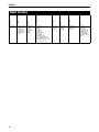
Delfield
S=Specification
Line
S=Stainless interior &
exterior
A=Stainless exterior,
aluminum interior
M=Stainless front,
aluminum sides and
interior
R=Refrigerator
F=Freezer
H=Heated
D=Dual Temp
T=Thaw
W=Wine
None=Reach-in
PT=Pass Thru
RI=Roll-in
RT=Roll Thru
FF=Fish Drawers
RL=Refrigerator Left
FL=Freezer Left
TR=Top Refrigerator
BR=Bottom Refrigerator
TP=Top Refrigerator Pass Thru
BP=Bottom Refrigerator Pass Thru
RP=Refrigerator Left Pass Thru
FP=Freezer Left Pass Thru
1=1 Section
2=2 Section
3=3 Section
None=Standard
N=Narrow
S=Shallow
None=Standard
E=Export Voltage
R=Remote
Doors
System
Size
Section
Configuration
Temp
Finish
Series
Model Numbers
S=Solid Full
SH=Solid Half
G=Hinged Glass Full
GH=Hinged Glass Half
SL=Sliding Glass Full
SLH=Sliding Glass Half
SLS=Sliding Solid Full
SLSH=Sliding Solid Half
D=Drawers
Specification Line
Introduction
Model numbers starting with the letters “SS” have a stainless
steel exterior and interior. Model numbers starting with the letters
“SA” have an aluminum interior and a stainless steel exterior.
Model numbers starting with the letters “SM” have an aluminum
interior and exterior with a stainless steel front and shroud. Door
gaskets are magnetic and mount to the door, snapping in place
and are removable without tools. Keyed door lock is mounted
in the door next to the handle.
Doors can be removed from the cabinet without the use of
tools. Each door has two edge mount, self-closing, cam lift
style hinges.
Refrigeration System
All components are mounted to the exterior cabinet ceiling,
outside the food zone and are assembled as one-piece and can be
removed as one-piece. Environmentally friendly R404A refrigerant
is used. The system has the capability of maintaining between 27°F
and 40°F (-3°C and 4°C) in heavy use food service operations.
Refrigerant is metered using a highly responsive thermostatic
expansion valve. Systems are controlled using Delfield’s ETC1
Electronic Temperature Control. It provides improved pull down
times, reducing compressor cycling and longer compressor life
with lower energy consumption. Control system uses adaptive
defrost to assure evaporator coil is free of ice and operating at
optimum efficiency. Evaporator condensate is eliminated using
an energy efficient hot gas system.
Freezer Refrigeration System
All components are mounted to the exterior cabinet ceiling, outside
the food zone and are assembled as one-piece and can be removed
as one-piece. Environmentally friendly R404A refrigerant is used.
The system has the capability of maintaining between -5°F and
0°F (-21°C and -18°C) in heavy use food service operations.
Refrigerant is metered using a highly responsive thermostatic
expansion valve. System is controlled using Delfield’s ETC1
Electronic Temperature Control, which provides improved pull
down times, reducing compressor cycling and longer compressor
life with lower energy consumption. Control system uses adaptive
defrost to assure evaporator coil is free of ice and operating at
optimum efficiency. Evaporator condensate is eliminated using
an energy efficient hot gas system.
Dual Temperature Refrigeration/Freezer
Each compartment has its own separate refrigeration system.
Condensing units are located on top of the cabinet, outside
the food zone, behind the upper shroud. Evaporator coils are
located inside the cabinet mounted to the interior ceiling of each
compartment. Defrost is automatic. Condensate travels down
a tube in the cabinet sidewall to a receptacle mounted to the
exterior bottom of the cabinet where it evaporates with the aid of
an electric heater. Each compartment’s temperature is individually
monitored and controlled with Delfield's ETC1 Electronic
Temperature Control. Two exterior digital thermometers monitor
temperature. Refrigerator compartment maintains temperature
between 33°F and 41°F (1°C and 5°C). Freezer compartment
maintains temperature between -5°F and +5°F (-21°C and -15°C).
Refrigerant is metered using a highly responsive thermostatic
expansion valve.
Ready Thaw
Ready Thaw is designed to thaw frozen food under controlled
temperature conditions in approximately 18 hours and then
hold it at normal refrigerator temperatures. This unit uses a
standard refrigeration system mounted to the exterior cabinet
ceiling coupled with a heater and fan mounted in the center of
the refrigerated cabinet. The unit will operate as a standard
refrigerator and maintain a temperature of between 33°F and
41°F (1°C and 5°C)until a quantity of frozen product drops the
temperature below 20°F (7°C). The control will then automatically
cycle the heater and fan to begin the thaw process. After the
product is thawed, the electronic control will turn off the heater
and fan and return to standard refrigeration operation.
Heating System
Heating system cabinets are designed to maintain temperatures
between 120°F and 200°F (49°C and 93°C). Heating elements
are helical shaped, with tubular fins. A circulating fan provides
uniform airflow in the cabinet. The entire heating system is
mounted to the exterior of the cabinet ceiling, outside the food
zone. It is assembled as one piece and can be removed as one
piece. An adjustable electronic thermostat controls temperature.
The system ON/OFF switch is located on the front exterior of
the cabinet.
Delfield
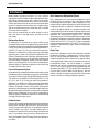
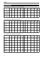
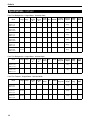
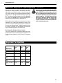
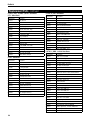
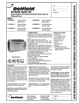
Specifications
Reach-In Refrigerators - Hinged Doors - Standard Width & Depth
Voltage
Amps
Storage
Capacity
Ft3
Shelf
Capacity
Ft2
No. Of
Shelves
H.P.
BTU/HR
R-404A
Charge Oz.
Shipping
Weight
NEMA
Plug
Energy
(KWH)
SSR1-S,SH,G,GH
SAR1-S,SH,G,GH
SMR1-S,SH,G,GH
115
6.8
24.96
12.81
3
1/4
2092
12.5
418lbs/
190kg
5-15P
2.64
SSR2-S,SH,G,GH
SAR2-S,SH,G,GH
SMR2-S,SH,G,GH
115
9.0
51.92
27.54
6
1/3
3226
19
650lbs/
295kg
5-15P
4.51
SSR3-S,SH,G,GH
SAR3-S,SH,G,GH
SMR3-S,SH,G,GH
115
16.0
78.89
42.47
9
1/2
5465
24
830lbs/
376kg
5-20p
5.51
Model
Reach-In Refrigerators - Hinged Doors - Narrow Width
Voltage
Amps
Storage
Capacity
Ft3
Shelf
Capacity
Ft2
No. Of
Shelves
H.P.
BTU/HR
R-404A
Charge Oz.
Shipping
Weight
NEMA
Plug
Energy
(KWH)
SSR1N-S,SH
SAR1N-S,SH
SMR1N-S,SH
115
6.8
20.97
10.59
3
1/4
2092
12.5
398lbs/
181kg
5-15P
3.16
SSR1N-G,GH
SAR1N-G,GH
SMR1N-G,GH
115
6.8
20.97
10.59
3
1/4
2092
12.5
398lbs/
181kg
5-15P
4.04
SSR2N-S,SH
SAR2N-S,SH
SMR2N-S,SH
115
9.0
43.94
23.10
6
1/3
3226
19
588lbs/
267kg
5-15P
4.31
SSR2N-G,GH
SAR2N-G,GH
SMR2N-G,GH
115
9.0
43.94
23.10
6
1/3
3226
19
588lbs/
267kg
5-15P
5.95
Model
Reach-In Refrigerators - Hinged Doors - Shallow Depth
Voltage
Amps
Storage
Capacity
Ft3
Shelf
Capacity
Ft2
No. Of
Shelves
H.P.
BTU/HR
R-404A
Charge Oz.
Shipping
Weight
NEMA
Plug
Energy
(KWH)
SSR1S-S,SH
SAR1S-S,SH
SMR1S-S,SH
115
6.8
18.25
12.81
3
1/4
2092
12.5
396lbs/
180kg
5-15P
2.66
SSR1S-G,GH
SAR1S-G,GH
SMR1S-G,GH
115
6.8
18.25
12.81
3
1/4
2092
12.5
396lbs/
180kg
5-15P
3.55
SSR2S-S,SH
SAR2S-S,SH
SMR2S-S,SH
115
7.8
37.96
27.54
6
1/3
2488
19
586lbs/
266kg
5-15P
2.98
SSR2S-G,GH
SAR2S-G,GH
SMR2S-G,GH
115
7.8
37.96
27.54
6
1/3
2488
19
586lbs/
266kg
5-15P
5.24
SSR3S-S,SH
SAR3S-S,SH
SMR3S-S,SH
115/
208-230
7.8
57.57
42.47
9
1/2
5465
24
795lbs/
361kg
N/A
7.49
SSR3S-G,GH
SAR3S-G,GH
SMR3S-G,GH
115
8.9
57.57
42.47
9
1/2
3637
17
795lbs/
361kg
N/A
9.14
Model
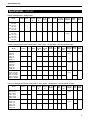
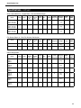
Specification Line
Specifications, continued
Reach-In Refrigerators - Sliding Doors
Voltage
Amps
Storage
Capacity
Ft3
Shelf
Capacity
Ft2
No. Of
Shelves
H.P.
BTU/HR
R-404A
Charge Oz.
Shipping
Weight
NEMA
Plug
Energy
(KWH)
SSR2-SLS,SLSH,
SLG,SLGH
SAR2-SLS,SLSH,
SLG,SLGH
SMR2-SLS,SLSH,
SLG,SLGH
115
9.0
51.92
27.54
6
1/3
3226
19
670lbs/
304kg
5-15P
N/A
SSR2S-SLS,SLSH,
SLG,SLGH
SAR2S-SLS,SLSH,
SLG,SLGH
SMR2S-SLS,SLSH,
SLG,SLGH
115
7.8
37.96
27.54
6
1/3
2488
12.5
670lbs/
304kg
5-15P
N/A
Model
Reach-In Refrigerator/Freezer Combinations - Dual Temps - Hinged Doors - Standard Width & Depth
Section
V
Amps
Storage
Capacity
Ft3
Shelf
Capacity
Ft2
No. Of
Shelves
H.P.
BTU/
HR
R-404A
Charge
Oz.
SSDTR1-SH,
SSDBR1-SH,
SADTR1-SH,
SADBR1-SH,
SMDTR1-SH,
SMDBR1-SH
Refrigerator
115
12.0
10.81
4.23
2
1/5
1543
11
Freezer
115
10.81
4.23
2
1/4
1260
12
SSDTR1-GH,
SSDBR1-GH,
SADTR1-GH,
SADBR1-GH,
SMDTR1-GH,
SMDBR1-GH
Refrigerator
115
10.81
4.23
2
1/5
1543
11
Freezer
115
10.81
4.23
2
1/4
1260
12
SSDRL2-S,SH,G,GH
SSDFL2-S,SH,G,GH
SADRL2-S,SH,G,GH
SADFL2-S,SH,G,GH
SMDRL2-S,SH,G,GH
SMDFL2-S,SH,G,GH
Refrigerator
115
6.8
24.96
12.81
3
1/4
2092
12.5
Freezer
115
7.8
24.96
12.81
3
1/2
1516
12.5
Model
12.0
Shipping
Weight
NEMA
Plug
Energy
(KWH)
525lbs/
238kg
5-20P
6.70
525lbs/
238kg
5-20P
N/A
730lbs/
331kg
5-15P
N/A
5-15P
Pass-Thru Refrigerator/Freezer Combinations - Dual Temps - Hinged Doors - Standard Width & Depth
Section
V
Amps
Storage
Capacity
Ft3
Shelf
Capacity
Ft2
No. Of
Shelves
H.P.
BTU/
HR
R-404A
Charge
Oz.
SSDTP1-SH,GH
SSDBP1-SH,GH
SADTP1-SH,GH
SADBP1-SH,GH
SMDTP1-SH,GH
SMDBP1-SH,GH
Refrigerator
115
14.0
12.19
4.23
2
1/5
1543
10
Freezer
115
12.19
4.23
2
1/3
1260
12
SSDRP2-S,SH,
SSDFP2-S,SH
SADRP2-S,SH,
SADFP2-S,SH
SMDRP2-S,SH,
SMDFP2-S,SH
Refrigerator
115
6.8
24.96
12.81
3
1/4
2092
19
Freezer
115
11.5
24.96
12.81
3
3/4
1923
12.5
Model
Shipping
Weight
NEMA
Plug
Energy
(KWH)
525lbs/
238kg
5-20P
N/A
730lbs/
331kg
5-15P
N/A
5-15P
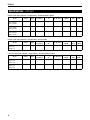
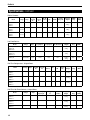
Delfield
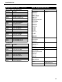
Specifications, continued
Reach-In Hot Food Cabinets - Hinged Doors - Standard Width & Depth
Voltage
Amps
Storage
Capacity Ft3
Shelf Capacity
Ft2
No. Of Shelves
Shipping
Weight
NEMA
Plug
Energy
(KWH)
SSH1-S,SH,G,GH
SAH1-S,SH,G,GH
SMH1-S,SH,G,GH
120/208-240
9.0
24.96
12.81
3
418lbs/190kg
N/A
N/A
SSH2-S,SH,G,GH
SAH2-S,SH,G,GH
SMH2-S,SH,G,GH
120/208-240
16.0
51.92
27.54
6
650lbs/295kg
N/A
N/A
SSH3-S,SH,G,GH
SAH3-S,SH,G,GH
SMH3-S,SH,G,GH
120/208-240
17.8
78.89
42.47
9
830lbs/376kg
N/A
N/A
Model
Reach-In Hot Food Cabinets - Hinged Doors - Narrow Width
Model
SSH2N-S,SH
SAH2N-S,SH
SMH2N-S,SH
Voltage
Amps
Storage
Capacity Ft3
Shelf Capacity
Ft2
No. Of Shelves
Shipping
Weight
NEMA
Plug
Energy
(KWH)
120/208-240
16.0
43.94
27.54
6
588lbs/267kg
N/A
N/A
Pass-Thru Hot Food Cabinets - Hinged Doors - Standard Width & Depth
Voltage
Amps
Storage
Capacity Ft3
Shelf Capacity
Ft2
No. Of Shelves
Shipping
Weight
NEMA
Plug
Energy
(KWH)
SSHPT1-S,SH
SAHPT1-S,SH
SMHPT1-S,SH
120/208-240
9.0
26.96
12.81
3
398lbs/181kg
N/A
N/A
SSHPT2-S,SH
SAHPT2-S,SH
SMHPT2-S,SH
120/208-240
16.0
51.92
27.54
6
650lbs/295kg
N/A
N/A
Model
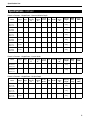
Specification Line
Specifications, continued
Reach-In Freezers - Hinged Doors - Standard Width & Depth
Voltage
Amps
Storage
Capacity
Ft3
Shelf
Capacity
Ft2
No. Of
Shelves
H.P.
BTU/HR
R-404A
Charge
Oz.
SSF1-S,SH
SAF1-S,SH
SMF1-S,SH
115
7.8
24.96
12.81
3
1/2
1516
SSF1-G,GH
SAF1-G,GH
SMF1-G,GH
115
11.5
24.96
12.81
3
3/4
SSF2-S,SH
SAF2-S,SH
SMF2-S,SH
115
14.3
51.92
27.54
6
SSF2-G,GH
SAF2-G,GH
SMF2-G,GH
115/
208-230
10.0
51.92
27.54
SSF3-S,SH
SAF3-S,SH
SMF3-S,SH
115/
208-230
10.0
78.89
SSF3-G,GH
SAF3-G,GH
SMF3-G,GH
115/
208-230
11.4
78.89
Model
Shipping
Weight
NEMA
Plug
Energy
(KWH)
12.5
440lbs/
200kg
5-15p
7.63
1923
12.5
440lbs/
200kg
5-15p
11.29
3/4
2648
17
710lbs/
322kg
5-20P
15.16
6
1
4793
30
710lbs/
322kg
N/A
19.95
42.47
9
1
4793
30
960lbs/
435kg
N/A
16.26
42.47
9
1
5940
72
960lbs/
435kg
N/A
29.07
Shipping
Weight
NEMA
Plug
Energy
(KWH)
Reach-In Freezers - Hinged Doors - Narrow Width
Voltage
Amps
Storage
Capacity
Ft3
Shelf
Capacity
Ft2
No. Of
Shelves
H.P.
BTU/HR
R-404A
Charge
Oz.
SSF1N-S,SH
SAF1N-S,SH
SMF1N-S,SH
115
7.8
20.97
10.59
3
1/2
1516
12.5
408lbs/
185kg
5-15p
7.58
SSF2N-S,SH
SAF2N-S,SH
SMF2N-S,SH
115
14.3
43.94
23.10
6
3/4
2648
17
680lbs/
308kg
5-20P
11.13
Shipping
Weight
NEMA
Plug
Energy
(KWH)
Model
Reach-In Freezers - Hinged Doors - Shallow Depth
Voltage
Amps
Storage
Capacity
Ft3
Shelf
Capacity
Ft2
No. Of
Shelves
H.P.
BTU/HR
R-404A
Charge
Oz.
SSF1S-S,SH
SAF1S-S,SH
SMF1S-S,SH
115
7.8
18.25
8.98
3
1/2
1516
12.5
406lbs/
184kg
5-15p
8.04
SSF2S-S,SH
SAF2S-S,SH
SMF2S-S,SH
115
11.5
37.96
19.04
6
3/4
1923
17
676lbs/
307kg
5-15P
10.55
SSF3S-S,SH
SAF3S-S,SH
SMF3S-S,SH
115/
208-230
11.5
57.67
29.10
9
1
4793
30
909lbs/
412kg
N/A
19.78
Model
Delfield
Specifications, continued
Pass-Thru Refrigerators - Hinged Doors - Standard Width
Voltage
Amps
Storage
Capacity
Ft3
Shelf
Capacity
Ft2
No. Of
Shelves
H.P.
BTU/HR
R-404A
Charge Oz.
Shipping
Weight
NEMA
Plug
Energy
(KWH)
SSRPT1-S,SH
SARPT1-S,SH
SMRPT1-S,SH
115
6.8
26.64
12.81
3
1/4
2092
12.5
455lbs/
206kg
5-15P
3.14
SSRPT1-G,GH
SARPT1-G,GH
SMRPT1-G,GH
115
7.8
26.64
12.81
3
1/3
2488
12.5
455lbs/
206kg
5-15P
4.58
SSRPT2-S,SH
SARPT2-S,SH
SMRPT2-S,SH
115
16.0
55.42
27.54
6
1/2
5465
24
700lbs/
318kg
5-20P
5.96
SSRPT2-G,GH
SARPT2-G,GH
SMRPT2-G,GH
115
16.0
55.42
27.54
6
1/2
5465
24
700lbs/
318kg
5-20P
8.16
SSRPT3-S,SH
SARPT3-S,SH
SMRPT3-S,SH
115
16.0
84.19
42.47
9
1/2
5465
24
972lbs/
441kg
N/A
8.84
SSRPT3-G,GH
SARPT3-G,GH
SMRPT3-G,GH
115/
208-230
12.4
84.19
42.27
9
3/4
7569
48
972lbs/
441kg
N/A
14.50
Model
Pass-Thru Refrigerators - Hinged Doors - Shallow Depth
Voltage
Amps
Storage
Capacity
Ft3
Shelf
Capacity
Ft2
No. Of
Shelves
H.P.
BTU/HR
R-404A
Charge Oz.
Shipping
Weight
NEMA
Plug
Energy
(KWH)
SSRPT1S-S,SH
SARPT1S-S,SH
SMRPT1S-S,SH
115
7.8
18.25
8.98
3
1/3
2488
12.5
455lbs/
206kg
5-15P
N/A
SSRPT2S-S,SH
SARPT2S-S,SH
SMRPT2S-S,SH
115
16.0
37.96
19.04
6
1/2
5465
24
700lbs/
318kg
5-20P
N/A
Model
Pass-Thru Freezers - Hinged Doors - Standard Width
Voltage
Amps
Storage
Capacity
Ft3
Shelf
Capacity
Ft2
No. Of
Shelves
H.P.
BTU/HR
R-404A
Charge Oz.
Shipping
Weight
NEMA
Plug
Energy
(KWH)
SSFPT1-S,SH
SAFPT1-S,SH
SMFPT1-S,SH
115
11.5
26.64
12.81
3
3/4
1923
12.5
672lbs/
305kg
5-15p
11.30
SSFPT2-S,SH
SAFPT2-S,SH
SMFPT2-S,SH
115/
208-230
10.0
55.42
27.54
6
1
4793
30
1001lbs/
454kg
N/A
14.26
SSFPT3-S,SH
SAFPT3-S,SH
SMFPT3-S,SH
115/
208-230
10.0
84.19
42.27
9
1-1/2
5185
64
1268lbs/
575kg
N/A
33.00
Model
10
Specification Line
Specifications, continued
Wine Cabinet Reach-In - Hinged Doors - Standard Width & Depth
Voltage
Amps
Storage
Capacity
Ft3
Shelf
Capacity
Ft2
No. Of
Shelves
H.P.
BTU/HR
R-404A
Charge Oz.
Shipping
Weight
NEMA
Plug
Energy
(KWH)
SSW1-S, SH, G, GH
SAW1-S, SH, G, GH
SMW1-S, SH, G, GH
115
6.8
24.96
12.81
3
1/4
2092
12.5
418lbs/
190kg
5-15P
N/A
SSW2-S, SH, G, GH
SAW2-S, SH, G, GH
SMW2-S, SH, G, GH
115
9.0
51.92
27.54
6
1/3
3226
19
650lbs/
295kg
5-15P
N/A
SSW3-S, SH, G, GH
SAW3-S, SH, G, GH
SMW3-S, SH, G, GH
115
16.0
78.89
42.47
9
1/2
5465
24
830lbs/
376kg
5-20P
N/A
Model
Fish Drawer Reach-In - Four Fish Drawers Per Section
Voltage
Amps
Storage
Capacity
Ft3
Shelf
Capacity
Ft2
No. Of
Shelves
H.P.
BTU/HR
R-404A
Charge Oz.
Shipping
Weight
NEMA
Plug
Energy
(KWH)
SSRFF1
115
6.8
24.96
N/A
N/A
1/4
2092
12.5
418lbs/
190kg
5-15P
N/A
SSRFF2
115
9.0
51.92
N/A
N/A
1/3
3226
19
650lbs/
295kg
5-15P
N/A
Voltage
Amps
Storage
Capacity
Ft3
Shelf
Capacity
Ft2
No. Of
Shelves
H.P.
BTU/HR
R-404A
Charge Oz.
Shipping
Weight
NEMA
Plug
Energy
(KWH)
SSRRI1-S
SARRI1-S
SMRRI1-S
115
6.8
36.15
N/A
N/A
1/4
2092
12.5
476lbs/
216kg
5-15P
3.79
SSRRI1-G
SARRI1-G
SMRRI1-G
115
7.8
36.15
N/A
N/A
1/3
2488
12.5
476lbs/
216kg
5-15P
5.46
SSRRI2-S
SARRI2-S
SMRRI2-S
115
9.0
74.72
N/A
N/A
1/3
3226
24
768lbs/
348kg
5-15P
5.86
SSRRI2-G
SARRI2-G
SMRRI2-G
115
16.0
74.72
N/A
N/A
1/2
5465
24
768lbs/
348kg
5-20P
9.28
SSRRI3-S
SARRI3-S
SMRRI3-S
115
16.0
113.28
N/A
N/A
1/2
5465
24
1044lbs/
4774kg
5-20p
7.56
SSRRI3-G
SARRI3-G
SMRRI3-G
115/
208-230
10.0
113.28
N/A
N/A
3/4
6920
48
1044lbs/
4774kg
N/A
17.12
Model
Roll-In Refrigerators
Model
11
Delfield
Specifications, continued
Roll-In Freezers
Voltage
Amps
Storage
Capacity
Ft3
Shelf
Capacity
Ft2
No. Of
Shelves
H.P.
BTU/HR
R-404A
Charge Oz.
Shipping
Weight
NEMA
Plug
Energy
(KWH)
SSFRI1-S
SAFRI1-S
SMFRI1-S
115
7.8
36.15
N/A
N/A
1/2
1516
12.5
497lbs/
225kg
5-15p
11.57
SSFRI2-S
SAFRI2-S
SMFRI2-S
115/
208-230
10.0
74.12
N/A
N/A
1
4793
30
824lbs/
374kg
N/A
21.02
SSFRI3-S
SAFRI3-S
SMFRI3-S
115/
208-230
11.8
113.28
N/A
N/A
1-1/2
5394
64
1128lbs/
512kg
N/A
25.70
Voltage
Amps
Storage
Capacity Ft3
Shelf
Capacity Ft2
No. Of Shelves
Shipping
Weight
NEMA
Plug
Energy
(KWH)
SSHRI1-S,G
SAHRI1-S,G
SMHRI1-S,G
120/208-240
9.0
36.15
N/A
N/A
459lbs/
208kg
N/A
N/A
SSHRI2-S, G
SAHRI2-S, G
SMHRI2-S, G
120/208-240
16.0
74.72
N/A
N/A
704lbs/
319kg
N/A
N/A
SSHRI3-S, G
120/208-240
17.8
113.28
N/A
N/A
1008lbs/
457kg
N/A
N/A
Model
Hot Food Roll-Ins
Model
Roll-Thru Refrigerators - Hinged Doors
Voltage
Amps
Storage
Capacity
Ft3
Shelf
Capacity
Ft2
No. Of
Shelves
H.P.
BTU/
HR
R-404A
Charge
Oz.
SSRRT1-S
SARRT1-S
SMRRT1-S
115
7.8
38.58
N/A
N/A
1/3
2488
SSRRT2-S
SARRT2-S
SMRRT2-S
115
16.0
79.74
N/A
N/A
1/2
SSRRT3-S
SARRT3-S
SMRRT3-S
115/
208-230
11.3
120.90
N/A
N/A
3/4
Model
Shipping
Weight
NEMA
Plug
Energy
(KWH)
12.5
514lbs/
233kg
5-15P
3.97
5465
24
776lbs/
352kg
5-20P
6.77
7569
48
1116lbs/
506kg
N/A
8.01
Roll-Thru Hot Food Cabinets - Hinged Doors
Voltage
Amps
Storage
Capacity Ft3
Shelf Capacity
Ft2
No. Of
Shelves
Shipping
Weight
NEMA
Plug
Energy
(KWH)
SSHRT1-S
SAHRT1-S
SMHRT1-S
120/208-240
9.0
38.58
N/A
N/A
519lbs/
235kg
N/A
N/A
SSHRT2-S
SAHRT2-S
SMHRT2-S
120/208-240
16.0
79.74
N/A
N/A
836lbs/
379kg
N/A
N/A
SSHRT3-S
SAHRT3-S
120/208-240
17.8
120.90
N/A
N/A
985lbs/
447kg
N/A
N/A
Model
12
Specification Line
Specifications, continued
13
Delfield
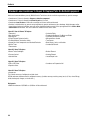
Installation
Location
Stabilizing
Cabinets represented in this manual are intended for indoor use
only. Be sure the location chosen has a floor strong enough to
support the total weight of the cabinet, 1000 pounds. per door
section. Reinforce the floor if necessary to provide for maximum
loading. For the most efficient operation, be sure to provide good
air circulation inside and out. The location should be selected so
that the power cord can be connected without any extensions.
It is very important that all legs are properly adjusted to keep
the cabinet level, evenly distribute the weight and to make sure
the unit will not rock, lean or be unstable.
Inside Unit
Take care not to block airflow to the fans or heating elements
and allow space along the front, back and sides.
Outside Unit
Be sure that the unit has access to ample air; avoid hot corners
and locations near stoves and ovens. Provide a minimum clearance
of 12” (30.5 cm) above the unit that is open to the front.
Due to the unique design of the One Door Dual Temp
units (ie: SSDTR1-SH), a 6" clearance is required at
the back of the unit to ensure proper operation.
Door Removal
The doors can be removed during installation if necessary.
Remove the door by opening the door to 90˚, lift it up and ease
it out of the hinge brackets
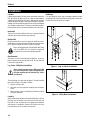
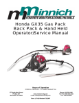
Leg, Caster, Utility Base Installation
Figure 1. Leg or Caster Installation
Some cabinets may weigh over 1000 pounds (450
kg). Use a lifting device capable of supporting the
unit when removing skid or installing legs, casters
WARNING or utility base.
To install the legs, or casters refer to Figure 1. To install the utility
base, refer to Figure 2. Proceed as follows:
1.
2.
3.
Remove unit from skid.
Raise unit to access leg/caster mounting holes on bottom
of unit.
Attach the legs, casters or utility base to bottom of cabinet
using hex head bolts.
Leveling
After the cabinet has been placed in the desired location, cabinets
with legs must be leveled. Level units from front to back and
from side to side. Leveling will insure proper door operation
and removal of condensate. Cabinets with casters must have
the caster brake set so the cabinet cannot move.
14
Figure 2. Utility Base Installation
Specification Line
Installation, continued
Electrical Connection
Refer to the amperage data list in the
SPECIFICATIONS or the serial tag data and your
local code or the National Electrical Code to be
sure the unit is connected to the proper power
source. A protected circuit of the correct voltage and
amperage must be run for connection of the supply
cord or permanent connection to the unit. The power
must be turned off and disconnected whenever
performing maintenance or repair functions.
Permanently connected units must be connected
in accordance with NEC Article 422 Appliances,
C-Disconnecting means. It is the responsibility of
the end user to provide the disconnect means to
satisfy the authority having jurisdiction.
The power cords supplied with this equipment are three-pronged
plugs and must be connected to a three-pronged wall outlet for
proper grounding. Do not use an adapter to connect to a twopronged outlet. The three pronged-outlet provides a ground
connection which must be used to prevent a shock hazard.
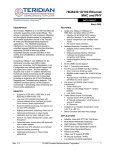
Figure 3. Plug Configurations
Have the wall outlet checked by a qualified
electrician to be sure a proper ground is present
and that the outlet provides the correct voltage and
required amperage to match the rating plate.
Any power cord that is frayed or damaged should be replaced.
When disconnecting the unit from the power source, do not pull
on the wire. Firmly grip the plug and remove from outlet.
The plugs shown in Figure 3 are used on the various models.
15
Delfield
Electronic Temperature Control Operation
The electronic temperature control constantly monitors box
temperature as well as evaporator coil temperature to maintain
consistent product temperatures. The control also sends
temperature readings to the digital temperature display. The
control circuits continually self-check and if an error occurs,
the digital display will switch from temperature read-out to
error read-out, i.e. E1. Even when an error is displayed, the
refrigeration and controls system should continue to function,
however not at optimal performance. Whenever the display has
an error read-out, Delfield Service should be contacted.
At initial start-up or anytime power is disconnected, then
reconnected to the unit, the control will delay all operations for
a short time (up to 10 minutes.) While in this delay period, the
control initializes the control parameters and confirms that the
temperature sensors and circuits are operational. The digital
temperature display will not display temperature OR errors until
the self-check is complete and the control has switched on the
evaporator fan motor, compressor and condenser fan motor.
Regarding Freezers: After initializing, the control will
immediately enter a DEFROST mode and the display
will read DEF. The compressor and condenser fan
as well as the evaporator fan will remain off until
initialization defrost is complete. This initial defrost
cycle may take up to 15 minutes to complete, at which
time the freezing cycle will begin. The display will
continue to read DEF for an additional 30 minutes
before displaying temperature.
The control is located in the control box in the top of the unit
behind the hinged louvered front panel. Refrigerators are factory
set at mid-range to maintain about 38ºF (3ºC) box temperature.
Freezers are factory set at mid-range to maintain about 3ºF
(-18ºC) box temperature. To adjust for colder temperatures,
turn the knob clockwise. For warmer temperatures, turn the
knob counter-clockwise. Turn the knob fully counter-clockwise
to turn the refrigeration system off. Never turn the knob more
than 1 dial number and always allow 8 hours for temperature
stabilization before making any additional adjustments.
Refrigerator:
Whenever the refrigerator is plugged in, and the control has
completed initializing, the evaporator fans will operate as described
in the Evaporator Operation Section. The digital temperature will
display box temperature in degrees F. The temperature control
will cycle the compressor and condenser fan motor to maintain
box temperature at the control setting.
16
Refrigerator Defrost
The temperature control also monitors the evaporator temperature
and will turn off the compressor and condenser fan motor when
needed to allow accumulated frost on the evaporator to clear.
During this defrost cycle, the digital temperature display will
read dEF. After the defrost cycle is complete, the temperature
control will return to a normal cooling cycle, but the display
will continue to read dEF until the evaporator returns to normal
cooling temperatures (up to 15 minutes).
Energy Saver Switch
The energy saver switch is a rocker switch located next to the
thermostat knob that controls the amount of heat applied to the
door perimeter. The normal operating position for this switch is the
ON position, providing the least heat. If excessive condensation
is observed on the door opening, press the energy saver switch
to the OFF position, to increase the amount of heat (red portion
of the rocker switch will be visible). Note: This feature is not
present on Dual Temperature models.
Freezer:
Whenever the freezer is plugged in, and the control has completed
initializing including the initial defrost cycle, the evaporator
fans will run continuously (except during a defrost cycle) and
the digital temperature display will display box temperature in
degrees F. The temperature control will cycle the compressor
and condenser fan motor to maintain box temperature at the
control setting.
Freezer Automatic Defrost
The control also monitors compressor total running time and
will enter a defrost cycle after total compressor running time is
greater than 4-hours since the last defrost cycle OR if evaporator
coil temperature drops below -34ºF (-37ºC) (indicating excessive
frost on the coil.)
Freezer Manual Defrost
If a manual defrost is desired, simply unplug the unit for several
seconds, then plug unit back in. This will cause the control to
re-initialize and then enter a defrost cycle.
Specification Line
Electronic Temperature Control Operation, continued
When the control enters the defrost mode, it switches off the
evaporator fan motor, compressor and condenser fan motor,
and switches on the defrost heater to warm the evaporator
coil. Thereby melting all frost accumulated during the previous
refrigeration cycle. The digital temperature display will now read
dEF. The control will continue the defrost cycle for a MINIMUM
of 8 minutes and a MAXIMUM of 30 minutes depending on the
amount of frost accumulated on the evaporator coil.
After the defrost cycle is complete, the control returns to a normal
refrigeration cycle, however the evaporator fan motor will not
switch on for 2 minutes AFTER the compressor and condenser
fan motor have begun operating. The digital temperature display
will continue to read dEF until the evaporator has returned to
normal freezing temperatures (up to 30 minutes).
Regarding Single Section Dual Temperature Units:
After initializing, the both controls will immediately
enter a DEFROST mode and the displays will read
DEF. The compressor and condenser fan as well as
the evaporator fan will remain off until initialization
defrost is complete. This initial defrost cycle may
take up to 15 minutes to complete, at which time
the freezing cycle will begin. The displays will
continue to read DEF for an additional 30 minutes
before displaying temperature.
Dual Temperature Refrigerator/Freezer Cabinets
These units combine both a refrigerator compartment and a
freezer compartment in the same cabinet. Each compartment has
its own separate refrigeration unit and Electronic Temperature
Control.
Evaporator Fan Operation
Model Family
Compressor Compressor Defrost
Cycle
Cycle
Cycle
On
Off
On
Std Refrigerator
Fan On
Fan On
Fan On
Std Freezer
Fan On
Fan On
Fan Off
Refg. 1-Sec Dual
Temp
Fan On
Fan Off
Fan On
Freezer, 1-Sec Dual
Temp
Fan On
Fan On
Fan Off
Refg. 2-Sec Dual
Temp
Fan On
Fan On
Fan On
Freezer, 2-Sec Dual
Temp
Fan On
Fan On
Fan Off
17
Delfield
Heated Cabinet Operation
The Heated units have a POWER ON/OFF switch located behind the
flip up shroud at the front top of the unit for controlling power to
the unit and an electronic thermostat for setting the temperature.
A circulating fan provides uniform airflow in the cabinet.
Power Up
1.
2.
3.
4.
5.
18
Check that unit is properly connected to the power
source.
Raise the shroud to access the controls.
Set the Main POWER ON/OFF switch, to the ON position.
Adjust the electronic thermostat to the desired temperature.
Allow unit to warm-up before use.
The unit surface is very hot! Avoid direct contact
with skin; use appropriate protective apparel, such
as gloves.
Power Down
1.
2.
3.
Turn the unit off by setting the POWER ON/OFF switch to
the OFF position
After use, allow unit to cool down.
Clean equipment as discussed in the MAINTENANCE section
of this manual.
Specification Line
Maintenance
Door Gasket Maintenance
Door gaskets require regular cleaning to prevent mold and
mildew build up and also to retain the elasticity of the gasket.
Gasket cleaning can be done with the use of warm soapy water.
Avoid full strength cleaning products on gaskets as this can
cause them to become brittle and crack. Never use sharp tools
or knives to scrape or clean the gasket. Gaskets can be easily
replaced and do not require the use of tools or an authorized
service person. The gaskets are “Dart” style and can be pulled
out of the groove in the door and new gaskets can be “pressed”
back into place.
Drain Maintenance - Base
Each unit has a drain located inside the unit that removes
the condensation from the evaporator coil and routes it to an
external condensate evaporator pan. Each drain can become
loose or disconnected during normal use. If you notice water
accumulation on the inside of the unit be sure the drain tube
is connected to the evaporator drain pan. If water is collecting
underneath the unit make sure the end of the drain tube is in
the condensate evaporator in the machine compartment. The
leveling of the unit is important as the units are designed to
drain properly when level. Be sure all drain lines are free of
obstructions.
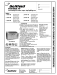
Drawer Maintenance
Drawer Assembly Cleaning
The drawer assembly is designed to be cleaned easily. Both
drawer and tracks are removable without tools. The drawer
tracks are dishwasher safe or can be cleaned in a sink with
detergents and a soft bristle brush. Drawers and tracks should
be cleaned on a weekly basis.
Remove Drawers
Pull the drawer box out until it stops. Lift up on the drawer front
and pull the drawer box completely out. Using a soft bristle
brush, clean the track on the bottom of the drawer box. When
finished, it should be wiped clean of all food and debris.
Tracks
The drawer box assembly must be removed. Pull the drawer
tracks out until they hit a stop. Locate blue safety clips towards
the back of each drawer track. Blue safety clips have a tab on
the top. Push the tab back until it clicks. Lift up and pull the
drawer tracks all the way
out of the drawer cage.
The drawer tracks are
dishwasher safe or can
be cleaned in a sink with
tab on top of
blue safety clip detergents and a soft
bristle brush. Drawers
and tracks should be cleaned on a weekly basis. Using a
soft bristle brush, wash the track making sure each roller is
thoroughly cleaned. The drawer cage should be cleaned with
a soft bristle brush, removing any food and debris gathered
on the bottom ledge. Once it’s cleaned thoroughly with a soft
bristle brush, wipe remaining debris clean with a soft towel.
Reassembly
Push the drawer tracks into the drawer cage. The blue safety
clip must remain pushed towards the back. Lift up and slide the
drawer track all the way into the drawer cage. The blue safety
clip will lock in place automatically. Once all tracks are replaced,
insert the drawer box. Rest the drawer box bottom track on the
front track roller. Then push the drawer back in place SLOWLY.
When the drawer box is about half way in you will hit a STOP.
You must lift the front of the drawer up approximately ½”
(1.3cm) to continue inward. Clean tracks as often as possible.
The cleaner the tracks are the better they will operate.
Caster Maintenance
Wipe casters with a damp cloth monthly to prevent corrosion.
The power switch must be turned to OFF and the
unit disconnected from the power source whenever
performing service, maintenance functions or
cleaning the refrigerated area.
Refrigerators and Freezers
The interior and exterior can be cleaned using soap and warm
water. If this isn’t sufficient, try ammonia and water or a
nonabrasive liquid cleaner. When cleaning the exterior, always
rub with the “grain” of the stainless steel to avoid marring the
finish. Do not use an abrasive cleaner because it will scratch the
stainless steel and can damage the breaker strips and gaskets.
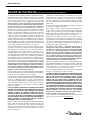
Stainless Steel Care and Cleaning
To prevent discoloration or rust on stainless steel several
important steps need to be taken. First, we need to understand
the properties of stainless steel. Stainless steel contains 70- 80%
iron, which will rust. It also contains 12-30% chromium, which
forms an invisible passive film over the steel’s surface, which
acts as a shield against corrosion. As long as the protective
layer is intact, the metal is still stainless. If the film is broken
or contaminated, outside elements can begin to breakdown the
steel and begin to form discoloration or rust. Proper cleaning of
stainless steel requires soft cloths or plastic scouring pads.
NEVER USE STEEL PADS, WIRE BRUSHES OR SCRAPERS!
Cleaning solutions need to be alkaline based or non-chloride
cleaners. Any cleaner containing chlorides will damage
the protective film of the stainless steel. Chlorides are also
commonly found in hard water, salts, and household and
industrial cleaners. If cleaners containing chlorides are used be
sure to rinse repeatedly and dry thoroughly. Routine cleaning
of stainless steel can be done with soap and water. Extreme
stains or grease should be cleaned with a non-abrasive cleaner
and plastic scrub pad. Always rub with the grain of the steel.
There are stainless steel cleaners available which can restore
and preserve the finish of the steels protective layer. Early signs
19
Delfield
Maintenance, continued
of stainless steel breakdown are small pits and cracks. If this
has begun, clean thoroughly and start to apply stainless steel
cleaners in attempt to restore the passivity of the steel.
Never use an acid based cleaning solution! Many
food products have an acidic content, which can
deteriorate the finish. Be sure to clean the stainless
steel surfaces of ALL food products. Common items
include, tomatoes, peppers and other vegetables.
Cleaning the Condenser Coil
In order to maintain proper refrigeration performance, the
condenser fins must be cleaned of dust, dirt and grease
regularly. It is recommended that this be done at least every
three months. If conditions are such that the condenser is totally
blocked in three months, the frequency of cleaning should be
increased. Clean the condenser with a vacuum cleaner or stiff
brush. If extremely dirty, a commercially available condenser
cleaner may be required.
Failure to maintain a clean condenser coil can initially cause high
temperatures and excessive run times. Continuous operation
with a dirty or clogged condenser coil can result in compressor
failure. Neglecting the condenser coil cleaning procedures will
void any warranties associated with the compressor and cost
to replace the compressor.
Never use a high-pressure water wash for this
cleaning procedure as water can damage the electrical
components located near or at the condenser coil.
Doors/Hinges
Over time and with heavy use doors the hinges may become
loose. If this happens tighten the screws that mount the hinge
brackets to the frame of the unit. Loose or sagging doors can
cause the hinges to pull out of the frame, which may damage
both the doors and the hinges. In some cases this may require
qualified service agents or maintenance personnel to perform
repairs.
Do not place hot pans on/against the grey ABS door
liner. Do not throw items into the storage area.
Failure to follow these recommendations could result
in damage to the interior of the cabinet or to the
blower coil. Overloading the storage area, restricting
the airflow, and continuous opening and closing of
the doors and drawers will hamper the units ability to
maintain operational temperature.
Preventing blower coil corrosion
To help prevent corrosion of the blower coil, store all acidic
items, such as pickles and tomatoes, in sealable containers.
Immediately wipe up all spills.
20
Continuous opening and closing of the doors will hamper the
unit’s ability to maintain optimum refrigeration temperature.
Specification Line
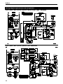
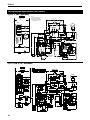
Wiring Diagram Specification Line Refrigerators
S_R1, S_R1N, S_R1S, S_RPT1, S_RPT1S, S_RRI1, S_RRT1, S_W1, SSRFF1 - Solid Doors
S_R1, S_R1N, S_R1S, S_RPT1, S_RRI1, S_W1 - Glass Doors
21
Delfield
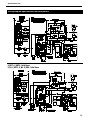
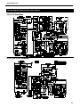
Wiring Diagram Specification Line Refrigerators
S_R2, S_R2N, S_R2S, S_R2-SL, S_R2S-SL, S_RPT2S, S_W2, S_RRI2 - Solid Doors
S_R2, S_R2N, S_R2S, S_R2-SL, S_R2S-SL, S_W2 - Glass Doors
22
Specification Line
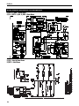
Wiring Diagram Specification Line Refrigerators
SSRFF2 - Solid Doors
S_RPT2, S_RRT2 - Solid Doors
S_R3, S_RPT3, S_W3, S_RRI3 - Solid Doors
23
Delfield
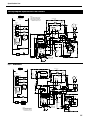
Wiring Diagram Specification Line Refrigerators
S_RPT2, S_RRI2 - Glass Doors
S_R3, S_RPT3, S_W3, S_RRI3 - Glass Doors
S_R3S - Solid & Glass Doors
S_RRT3 - Solid Doors
24
Specification Line
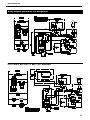
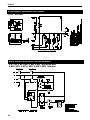
Wiring Diagram Specification Line Freezers
S_F1, S_F1N, S_F1S - Solid Doors
,
.
,).%6/,4!'%
3%%.!-%0,!4%&/2-!8)-5&53%3):%
./4%3
53%#/00%2#/.$5#4/23/.,9
4()35.)4-534"%'2/5.$%$
5.)43(/7.7)4(#/-02%33/2
25..).'!.$$//23#,/3%$
%6!0/2!4/2(/53).'
%6!0&!.
-/4/2
9
.
",5%
&
&!.2%,!9
0,5'
-
$%&2/34
(%!4%2
%6!0#/),
3%.3/2
#/.42/,
#)2#5)4
#!").%4!)2
3%.3/2
,
()'(4%-0
,)-)4
37)4#(
-
4%-0%2!452%
#/.42/,
7
%6!0/2!4/2&!.
).#!.$%3#%.4
,)'(4
(
(%!4%22%,!9
$%&2/34(%!4%2
#
#/-02%33/2
2%,!9
-
7
#/.42/,
"/8
%.%2'93!6%2
37)4#(
#/-02%33/2
7
7)4(",5%
342)0%3
7)2%
.54
7
0
7
,%$$)30,!9
)&53%$
-
30,)#%
",+
0/7%2"/8
#!").%4!)2
3%.3/2
%6!0#/),
3%.3/2
#/.$%.3/2&!.
'2%9
",+
34!24
#!0!#)4/2
7
",+
7
2%$
%.%2'93!6%2
37)4#(
# , , ( . &
4%-0%2!452%
#/.42/,
",+
$//2&2!-%
(%!4%2
7
7).$).'
02/4%#4/2
#/.$%.3%2
&!.
25.
7).$).
'
).#!.$%3#%.4
,)'(4
$//2
37)4#(
34!24
.'
7).$)
",+
$//2
().'%
37)4#(
",+
,%$$)30,!9
)&53%$
7
#/-02%33/2
&2!-%(%!4%23
S_F1 - Glass Doors
,
.
,).%6/,4!'%
3%%.!-%0,!4%&/2-!8)-5&53%3):%
%6!0/2!4/2(/53).'
%6!0&!.
-/4/2
",+
&,5/2%3#%.4,)'(4
"!,,!34
()'(4%-0
,)-)4
37)4#(
4%-0%2!452%
#/.42/,
.
&
&!.2%,!9
9
&,5/2%3#%.4,!-0
$%&2/34
(%!4%2
",5%
-
&,5/2%3#%.4,!-0!33%-",9
",+
%6!0/2!4/2&!.
%6!0#/),
3%.3/2
#/.42/,
#)2#5)4
",5%
#!").%4!)2
3%.3/2
,
2%$
&,5/2%3#%.4
,!-0
37)4#(
0,5'
7
(
(%!4%22%,!9
#
#/-02%33/2
2%,!9
$%&2/34(%!4%2
7
-
#/.42/,
"/8
#/-02%33/2
7
%.%2'93!6%2
37)4#(
7
7)4(",5%
342)0%3
7)2%
.54
7
0
,%$$)30,!9
)&53%$
7
#!").%4!)2
3%.3/2
%6!0#/),
3%.3/2
#/.$%.3/2&!.
30,)#%
",+
",+
'2%9
7
",+
%.%2'93!6%2
37)4#(
$//2&2!-%
(%!4%2
&,5/2%3#%.4
,!-0"!,,!34
# , , ( . &
4%-0%2!452%
#/.42/,
-/4/2
02/4%#4/2
25.#!0!#)4/2
3
34!24
7).$).'
#/.$%.3%2
&!.
&,5/2%3#%.4
,!-0
./4%3
53%#/00%2#/.$5#4/23/.,9
4()35.)4-534"%'2/5.$%$
5.)43(/7.7)4(#/-02%33/2
25..).'!.$$//23#,/3%$
2
-
",+
7
&,5/2%3#%.4
,!-037)4#(
-!).7).$).'
#
",+
7
0/7%2"/8
7
,%$$)30,!9
)&53%$
",+
.
.
,
,
34!24#!0!#)4/2
&2!-%(%!4%23
#/-02%33/2
25
Delfield
Wiring Diagram Specification Line Freezers
S_FPT1, S_FRI1 - Solid Doors
,
.
,).%6/,4!'%
3%%.!-%0,!4%&/2-!8)-5&53%3):%
./4%3
53%#/00%2#/.$5#4/23/.,9
4()35.)4-534"%'2/5.$%$
5.)43(/7.7)4(#/-02%33/2
25..).'!.$$//23#,/3%$
%6!0/2!4/2(/53).'
%6!0&!.
-/4/2
&
&!.2%,!9
9
.
0,5'
",5%
-
$%&2/34
(%!4%2
%6!0#/),
3%.3/2
#/.42/,
#)2#5)4
#!").%4!)2
3%.3/2
,
()'(4%-0
,)-)4
37)4#(
-
4%-0%2!452%
#/.42/,
%6!0/2!4/2&!.
).#!.$%3#%.4
,)'(4
(
(%!4%22%,!9
#
#/-02%33/2
2%,!9
$%&2/34(%!4%2
-
#/.42/,
"/8
#/-02%33/2
7
%.%2'93!6%2
37)4#(
7
7)4(",5%
342)0%3
7)2%
.54
7
0
7
-
30,)#%
",+
#/.$%.3/2&!.
7
#!").%4!)2
3%.3/2
%6!0#/),
3%.3/2
,%$$)30,!9
)&53%$
7
0/7%2"/8
'2%9
",+
-/4/2
02/4%#4/2
-!).7).$).'
#
",+
25.#!0!#)4/2
7
2%$
%.%2'93!6%2
37)4#(
",+
$//2&2!-%
(%!4%2
# , , ( . &
4%-0%2!452%
#/.42/,
7
3
).#!.$%3#%.4
,)'(4
$//2
().'%
37)4#(
",+
7
,%$$)30,!9
)&53%$
",+
.
.
,
,
S_F2, S_F2N, S_F2S - Solid Doors
26
34!24#!0!#)4/2
#/-02%33/2
&2!-%(%!4%23
34!24
7).$).'
#/.$%.3%2
&!.
$//2
37)4#(
2
-
Specification Line
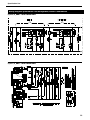
Wiring Diagram Specification Line Freezers
S_FPT2, S_FRI2 - Solid Doors
S_F2, S_F3 - Glass Doors
S_F3, S_F3S, S_FRI3 - Solid Doors
27
Delfield
Wiring Diagram Specification Line Freezers
S_FPT3 - Solid Doors
Wiring Diagram Specification Line Heated Models
S_H1, S_H2, S_H3, S_HRI1, S_HRI2, S_HRI3 - Solid & Glass Doors
S_H2N, S_HPT1, S_HPT2, S_HRT1, S_HRT2, S_HRT3 - Solid Doors
28
Specification Line
Wiring Diagram Specification Line Refrigerator/Freezer Combinations
S_DTR1, S_DBR1 - Solid & Glass Doors
S_DTP1, S_DBP1 - Solid & Glass Doors
29
Delfield
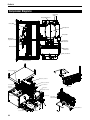
Compressor Diagrams
Capacitor,
start
Relay & Overload
Valve, EXP
Compressor
Drier, filter
Motor, fan,
evaporator
Motor, fan,
condensor
Blade, fan
Guard, fan,
condenser
Coil, condenser
Coil, evaporator
Fan delay, defrost limit
Blade, fan, condenser
Guard, fan, condenser
Coil, evaporator
Coil, condenser
Valve, EXP
Motor, fan,
evaporator
Compressor
Relay & Overload
Blade, fan
Capacitor, start
Fan delay,
defrost limit
Heater, defrost
Switch
Control switch
30
Drier, filter
Specification Line
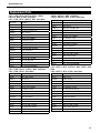
Replacement Parts
S_R1, S_R1N, S_R1S, S_RPT1, S_RPT1S, S_DRL2,
S_DFL2, S_DRP2, S_DFP2 - Solid Doors
S_R1, S_R1N, S_R1S, S_DRL2, S_DFL2 - Glass Doors
S_R2S, S_R2S-SL, S_RRT1 - Solid Doors
S_R2S, S_R2S-SL, S_RPT1, S_RRI1 - Glass Doors
Part Number
Description
Part Number
Description
2194792
Display, Blue, Danfoss
2194792
Display, Blue, Danfoss
3516433
Blade, Fan, 25
3516432
Blade, Fan, 25Deg, 8.75"
3517390
Blade, Fan, 5.56, CW, Lexan
3517390
Blade, Fan, 5.56, CW, Lexan
3516204A
Breaker, Vacuum
3516204A
Breaker, Vacuum
2194791
Cable, Display, 59
2194791
Cable, Display, 59
2194788
Capacitor, Start, 320MFD
2194787
Capacitor, Start, 280MFD
3516427
Coil, Condenser, Large
3516426
Coil, Condenser, Small
3516437
Coil, Evap, Ref, 1DR
3516437
Coil, Evap, Ref, 1DR
3527000
Comp, NF7.0,115V/60HZ
3526999
Comp, NF5.5CLX, 115V,60HZ
2194782KT
Control, Ref, Danfoss
3516444
Comp, Relay, Ovld, NF5.5CLX
3516322
Drier, Filter, (2)Inlet
2194782KT
Control, Ref, Danfoss
2160019
Guard, Fan, Wire
3516322
Drier, Filter, (2)Inlet
2162716
Motor, Fan, 16W, 115V,CW
2160019
Guard, Fan, Wire
2162715
Motor, Fan, Bay, 3/4ST
2162717
Motor, Fan, 9W, 115V, CW
3516438
Relay, Comp, Ovld, NF7CLX
2162715
Motor, Fan, Bay, 3/4ST
2190154
Switch, Rocker, 20A/125V
2190154
Switch, Rocker, 20A/125V
3516429
Valve, Therm EXP, W/O MOP
3516429
Valve, Therm EXP, W/O MOP
S_R2, S_R2N, S_R2-SL, S_RFF2, S_RRI2 - Solid Doors
S_R2, S_R2N, S_R2-SL - Glass Doors
S_R3, S_RPT2, S_RPT3, S_RPT2S, S_RRI3, S_RRT2 - Solid
Doors
S_R3, S_RPT2, S_RPT3, S_RRI2 - Glass Doors
Part Number
Description
Part Number
Description
2194792
Display, Blue, Danfoss
3516433
Blade, Fan, 25
3516433
Blade, Fan, 25
3516204A
Breaker, Vacuum
3516204A
Breaker, Vacuum
2194791
Cable, Display, 59
2194791
Cable, Display, 59
3516442
Capacitor, Start, Run, Assy
2194788
Capacitor, Start, 320MFD
3517344
Coil, Condenser, Lrg 2dr
3517343
Coil, Condenser, Small
3517341
Coil, Evap, Sml Ref, 2dr, Up
3517341
Coil, Evap, Sml Ref, 2dr, Up
3527016
Comp, SC15MLX.2,115V/60HZ
3527000
Comp, NF7.0,115V/60HZ
2194782KT
Control, Ref, Danfoss
2194782KT
Control, Ref, Danfoss
2194792
Display, Blue, Danfoss
3516322
Drier, Filter, (2)Inlet
3517345
Drier, Filter, 3/8", Danfoss
2160019
Guard, Fan, Wire
2160019
Guard, Fan, Wire
2162716
Motor, Fan, 16W, 115V,CW
2162716
Motor, Fan, 16W, 115V,CW
3516438
Relay, Comp, Ovld, NF7CLX
2190154
Switch, Rocker, 20A/125V
2190154
Switch, Rocker, 20A/125V
3516557
Valve, Thermal, Expansion
3516429
Valve, Therm EXP, W/O MOP
31
Delfield
Replacement Parts, continued
S_W1 - Solid & Glass Doors
S_W3 - Solid & Glass Doors
Part Number
Description
Part Number
Description
2194792
Display, Blue, Danfoss
2194792
Display, Blue, Danfoss
3516432
Blade, Fan, 25Deg, 8.75"
3516433
Blade, Fan, 25
3517390
Blade, Fan, 5.56, CW, Lexan
3516204A
Breaker, Vacuum
3516204A
Breaker, Vacuum
2194791
Cable, Display, 59
2194791
Cable, Display, 59
3516442
Capacitor, Start, Run, Assy
2194787
Capacitor, Start, 280MFD
3517344
Coil, Condenser, Lrg 2dr
3516426
Coil, Condenser, Small
3517341
Coil, Evap, Sml Ref, 2dr, Up
3516437
Coil, Evap, Ref, 1DR
3527016
Comp, SC15MLX.2,115V/60HZ
3526999
Comp, NF5.5CLX, 115V,60HZ
2194782-3KT
Control, Wine, W/O
3516444
Comp, Relay, Ovld, NF5.5CLX
3517345
Drier, Filter, 3/8", Danfoss
2194782-3KT
Control, Wine, W/O
2160019
Guard, Fan, Wire
3516322
Drier, Filter, (2)Inlet
2162716
Motor, Fan, 16W, 115V,CW
2160019
Guard, Fan, Wire
2190154
Switch, Rocker, 20A/125V
2162717
Motor, Fan, 9W, 115V, CW
3516557
Valve, Thermal, Expansion
2162715
Motor, Fan, Bay, 3/4ST
2190154
Switch, Rocker, 20A/125V
3516429
Valve, Therm EXP, W/O MOP
S_RRI3 - Glass Doors
Part Number
Description
3517390
Blade, Fan, 5.56, CW, Lexan
S_W2 - Solid & Glass Doors
3516308
Coil, Evap, R-404A
Part Number
Description
3526906
Cond Unit, FJEF-A075-CAV
2194792
Display, Blue, Danfoss
2194782KT
Control, Ref, Danfoss
3516433
Blade, Fan, 25
3516227
Drier, Filter, 5 CU. IN.
3516204A
Breaker, Vacuum
000-BAB-0033
Kit, Ref., Cntrl, 23D
2194791
Cable, Display, 59
2162691
Motor, Fan, 115V,50/60
2194788
Capacitor, Start, 320MFD
2190154
Switch, Rocker, 20A/125V
3517343
Coil, Condenser, Sml 2dr
3516330
Thermometer, 120V DIG
3517341
Coil, Evap, Sml Ref, 2dr, Up
3516316
Valve, EXP, R404A, 1/4-C
3516443
Comp, Cover, Small, Danfoss
3527000
Comp, NF7.0,115V/60HZ
2194782-3KT
Control, Wine, W/O
3516322
Drier, Filter, (2)Inlet
2160019
Guard, Fan, Wire
2162716
Motor, Fan, 16W, 115V,CW
3516438
Relay, Comp, Ovld, NF7CLX
2190154
Switch, Rocker, 20A/125V
3516429
Valve, Therm EXP, W/O MOP
32
S_RRT3 - Solid Doors
Part Number
Description
3517390
Blade, Fan, 5.56, CW, Lexan
3516308
Coil, Evap, R-404A
3526906
Cond Unit, FJEF-A075-CAV
2194782KT
Control, Ref, Danfoss
3516227
Drier, Filter, 5 CU. IN.
000-BAB-0033
Kit, Ref., Cntrl, 23D
2162691
Motor, Fan, 115V,50/60
3516330
Thermometer, 120V DIG
3516316
Valve, EXP, R404A, 1/4-C
Specification Line
Replacement Parts, continued
S_F1, S_F1N, S_F1S, S_DRL2, S_DFL2, S_FRI1 - Solid
Doors
S_DRL2, S_DFL2 - Glass Doors
S_F3, S_FPT2, S_FRI2 - Solid Doors
S_F2 - Glass Doors
Part Number
Description
Part Number
Description
3516433
Blade, Fan, 25
3516432
Blade, Fan, 25DEG, 8.75"
3516204A
3517390
Blade, Fan, 5.56, CW, Lexan
2194791
Breaker, Vacuum
Cable, Display, 59
3516204A
2194979
Capacitor, Run, 45 MFD
2194791
Breaker, Vacuum
Cable, Display, 59
2194978
Capacitor, Start, 145-175
2194789
Capacitor, Start, 240MFD
3517344
Coil, Condenser, Lrg 2dr
3516426
Coil, Condenser, Small
3517342
Coil, Evap, Lrg Frz, 2dr
3516436
Coil, Evap, Frz, 1DR
3527017
Comp, AWA2460ZXD, 208V/60H
3527001
Comp, SC12CLX.2, 115/60HZ
2194974
Contactor, 2 Pole, 120V
2194783KT
2194783KT
2194792
Control, Frz, Danfoss
Display, Blue, Danfoss
2194792
Control, Frz, Danfoss
Display, Blue, Danfoss
3516322
Drier, Filter, (2)Inlet
2160019
Guard, Fan, Wire
2160019
Guard, Fan, Wire
2194970
Heater, Defrost, 600W, 115V
2194785
Htr, Def, 400W, 115V, 1DR
2194953
Limit, High Defrost
2194953
Limit, High Defrost
2162716
Motor, Fan, 16W, 115V, CW
2162717
Motor, Fan, 9W, 115V, CW
2194980
Relay, Potential, Start
2162715
Motor, Fan, Bay, 3/4ST
2194959
Switch, Rocker, Snap-in
3516441
Relay, Comp, SC12CLX.2
3516557
Valve, Thermal, Expansion
2194959
Switch, Rocker, Snap-in
3516429
Valve, Therm Exp, W/O MOP
S_F2, S_F2N - Solid Doors
S_F3 - Glass Doors
Part Number
Description
3517390
Blade, Fan, 5.56, CW, Lexan
Part Number
Description
3516204A
Breaker, Vacuum
3516433
Blade, Fan, 25
3516305
Coil, Evap, R-404A
3516204A
3526917
Cond Unit, DJAL-0150-CAV
2194791
Breaker, Vacuum
Cable, Display, 59
2194991
Condensate Heater
3516442
Capacitor, Start, Run, Assy
3516043
Control, Temp, Frz
3517340
Coil, Evap, Sml FRZ, 2dr, Up
3516227
Drier, Filter, 5 CU. IN.
3527002
Comp, SC18CLX.2
2194046
Fan Delay/Defrost Limit
2194783KT
2194671
Heater, 115V, 400W, 2-PC
2194792
Control, Frz, Danfoss
Display, Blue, Danfoss
2194672
Heater, 115V, 500W, 10A, 2Ph
3516322
Drier, Filter, (2)Inlet
2162691
Motor, Fan, 115V,50/60
2160019
Guard, Fan, Wire
3516223
Regulator, Pressure, 5/8
2194970
Heater, Defrost, 600W, 115V
2194751
Relay, SPST-NO, 120V, FRZ
2194953
Limit, High Defrost
2190154
Switch, Rocker, 20A/125V
2162716
Motor, Fan, 16W, 115V, CW
3516330
Thermometer, 120V DIG
2194959
Switch, Rocker, Snap-in
2194260
Timer, Paragon Reach-in
3516557
Valve, Thermal, Expansion
3516280
Valve, EXP, R404A, FRZ, 1/2
3516041
Valve, Solenoid, 1/4ODF
33
Delfield
Replacement Parts, continued
S_F2S, S_FPT1, S_DRP2, S_DFP2 - Solid Doors
S_F1 - Glass Doors
S_FPT3, S_FRI3 - Solid Doors
Part Number
Description
Part Number
Description
2162500
Blade, Evap Fan, Morrel 7
3516433
Blade, Fan, 25
3516204A
Breaker, Vacuum
3517390
Blade, Fan, 5.56, CW, Lexan
3516305
Coil, Evap, R-404A
3516204A
3526918
Cond Unit, DJAL-0150-CAV
2194791
Breaker, Vacuum
Cable, Display, 59
3516043
Control, Temp, Frz
3516442
Capacitor, Start, Run, Assy
3516227
Drier, Filter, 5 CU. IN.
3516427
Coil, Condenser, Large
2194046
Fan Delay/Defrost Limit
3516436
Coil, Evap, Frz, 1DR
2194671
Heater, 115V, 400W, 2-PC
3527002
Comp, SC18CLX.2
2194672
Heater, 115V, 500W, 10A, 2Ph
2194783KT
2162667
Motor, Fan, 115V/60HZ
2194792
Control, Frz, Danfoss
Display, Blue, Danfoss
3516223
Regulator, Pressure, 5/8
2160019
Guard, Fan, Wire
3516330
Thermometer, 120V DIG
2194785
Htr, Def, 400W, 115V, 1DR
2194260
Timer, Paragon Reach-in
2194953
Limit, High Defrost
3516317
Valve, EXP, R404A, 1/2-Z
2162716
Motor, Fan, 16W, 115V, CW
2162715
Motor, Fan, Bay, 3/4ST
2194959
Switch, Rocker, Snap-in
S_F3S - Solid Doors
S_DTR1, S_DBR1 - Solid & Glass Doors
Part Number
Description
3516172
Blade, Fan, 5.56, CCW
3516432
Blade, Fan, 25deg, 8.75", Cw
Part Number
Description
3516426
Coil, Condenser, Small, Upright
3517390
Blade, Fan, 5.56, CW, Lexan
3516239
Coil, Evap, Refrig., RT, Spec
3516204A
Breaker, Vacuum
3516220
Coil, Evap, Frz, RT, Spec
3516305
Coil, Evap, R-404A
3526999
Compressor, Frz., Nf5.5clx, 115v,60hz
3526916
Cond Unit, DJAL-0100-CAV
3526997
Compressor, Ref., Tf4clx
3516043
Control, Temp, Frz
3516443
Compressor Cover, Frz/Ref, Small, Danfoss
3516227
Drier, Filter, 5 CU. IN.
2194783-5KT
Control, Frz, Danfoss, Etc1h, 115v
2194046
Fan Delay/Defrost Limit
2194783-6KT
Control, Ref, Danfoss, Etc1h, 115v
2194671
Heater, 115V, 400W, 2-PC
3516322
Drier, Filter, (2)inlet 1/4"
2194672
Heater, 115V, 500W, 10A, 2Ph
2160019
Guard, Fan, Wire
2162691
Motor, Fan, 115V,50/60
3516173
Guard, Plastic, Fan, 6
3516223
Regulator, Pressure, 5/8
3978197
Guard, Wire, Evaporator
2194751
Relay, SPST-NO, 120V, FRZ
2194659
Heater, 115V-100W, 1A
3516330
Thermometer, 120V DIG
2194670
Heater, 115V-305W, 3A
2194260
Timer, Paragon Reach-in
2194679
Heater, Drain, 120V-3.75W
3516280
Valve, EXP, R404A, FRZ, 1/2
2162717
Motor, Fan, 9w, 115v, Cw
2162691
Motor, Fan, 115V, 50/60
3516446
Relay, Comp, Ref., Danfoss P/N 117u4148
3516444
Relay, Ovld, Comp, Frz, Nf5.5clx
2194787
Start, Capacitor, Frz/Ref, 280mfd
3516331
Switch, High Press, 1/4"Tube, 404a, 450
3517394
Valve, Exp, R404A, Frz, 1/4
3517393
Valve, Exp, R404A, Ref, 1/4
34
Specification Line
Replacement Parts, continued
S_DTP1, S_DBP1 - Solid & Glass Doors
Part Number
Description
3516172
Blade, Fan, 5.56, CCW
3516239
Coil, Evap, Dough, RT, Spec
3516220
Coil, Evap, Frz, RT, Spec
3526969
Cond Unit, 1/3HP, 404A, FRZ
3526968
Cond Unit, 1/5HP, 404A, REF
2194782KT
Control, REF, Danfoss
2194536
Control, Temp, In@40D/Out
2194046
Fan Delay/Defrost Limit
3516173
Guard, Plastic, Fan, 6
2194659
Heater, 115V-100W, 1A
2194670
Heater, 115V-305W, 3A
2194679
Heater, Drain, 120V-3.75W
2162691
Motor, Fan, 115V, 50/60
5066440
Switch, Rocker #SPDT-D8
3516330
Thermometer, 120V DIG
2194532
Thermostat, FRZ
RF000072
Timer, Defrost, Air-O
3516271
Valve, EXP, R404A, FRZ, 1/4
3516273
Valve, EXP, R404A, REF, 1/4
Shelf Replacement Parts
Model
Shelf Number
S_R1-S,SH,G,GH
S_RPT1-S,SH
S_RPT1S-S,SH
S_DRL2-S,SH,G,GH
S_DFL2-S,SH,G,GH
S_DRP2-S,SH,
S_DFP2-S,SH
S_R2-SLS,SLSH,SLG,SLGH
S_RPT1-G,GH
S_R3-S,SH,G,GH
S_RPT2-S,SH
S_RPT2-G,GH
S_RPT3-S,SH
S_RPT3-G,GH
S_F1-S,SH
S_F2-S,SH
S_F2-G,GH
S_F3-S,SH
S_FPT2-S,SH
S_F3-G,GH
S_F1-G,GH
S_FPT1-S,SH
S_FPT3-S,SH
3978170
S_H1-S,SH,G,GH
S_H2-S,SH,G,GH
S_HPT1-S,SH
S_HPT2-S,SH
3978171
3978172
Part Number
Description
2162516
Blower, Hi-Temp, Reach-In
S_R1N-S,SH,G,GH
S_R2N-S,SH,G,GH
S_F1N-S,SH
S_F2N-S,SH
2194377
Control Knob
S_H2N-S,SH
3978173
2194645
Heating, Elem, Fin, 900W
Relay, Timer, 120V, 1HP
2162517
Ring, Inlet, Hi-Temp
2194370
Sensor, Temp, Htd Cab
2194409
Switch, Rocker, 20A, 2HP
3516330
Thermometer, 120V Dig, TI
S_R1S-S,SH,G,GH
S_R2S-S,SH,G,GH
S_R2S-SLS,SLSH,SLG,SLGH
S_RPT2S-S,SH
S_F1S-S,SH
S_F2S-S,SH
S_F3S-S,SH
3978174
2194618
000-C1A-0001
Thermostat, Hi-Limit
3978183
2194372
Thermostat, Htd Cabinet
S_W1-S, SH, G, GH
S_W2-S, SH, G, GH
S_W3-S, SH, G, GH
All Models
3234617KT Hinge, 1-5/16" Offset
with adjustable housing
All Models
3234782 Shelf Clip, SS
All Heated Models
35
Delfield
Standard Labor Guidelines To Repair Or Replace Parts On Delfield Equipment
Advice and recommendations given by Delfield Service Technicians do not constitute or guarantee any special coverage.
•A maximum of 1-hour is allowed to diagnose a defective component.
•A maximum of 1-hour is allowed for retrieval of parts not in stock.
•A maximum travel distance of 100 miles round trip and 2-hours will be reimbursed.
•Overtime, installation/start-up, normal control adjustments, general maintenance, glass breakage, freight damage, and/or
correcting and end-user installation error will not be reimbursed under warranty unless pre-approved with a Service Work
Authorization from Delfield. You must submit the number with the service claim.
Labor Of 1-Hour Is Allowed To Replace:
•Thermostat
•Door Jamb Switch
•Solenoid Coil
•Hi-limit/Thermal Protector Switch
•Fan Delay/Defrost Termination Switch
•Compressor Start Components and Overload Protector
•Defrost Timer
•Thermometer
Labor Of 2 Hours To Replace:
•Drawer Tracks/Cartridges
•Pressure Control
•Solenoid Valve
Labor Of 3 Hours To Replace:
•EPR or CPR Valve
•Expansion Valve
•
•
•
•
•
•
•
Contactor/Relay
Evaporator/Condenser Fan Motor and Blade
Circulating Fan Motor and Blade
Microprocessor Control
Transformer
Door Hinges, Locks, and Gaskets
Condensate Element
• Defrost Element
• Heating Element
• Locate/Repair Leak
• Condenser or Evaporator Coil
Labor Of 4 Hours To Replace:
•Compressor
This includes recovery of refrigerant and leak check.
$55.00 maximum reimbursement for refrigerant recovery (includes recovery machine, pump, torch, oil, flux, minor fittings,
solder, brazing rod, nitrogen, or similar fees.)
Refrigerants:
•R404A A maximum of $15.00/lb. or $1.00/oz. will be reimbursed.
36
Specification Line
Standard Two Year Warranty (Two year parts and labor, five year compressor)
The Delfield Company (“Delfield”) warrants to the Original Purchaser
of the Delfield product (herein called the “Unit”) that such Unit, and all
parts thereof, will be free from defects in material and workmanship
under normal use and service for a period of two (2) years from
the date of shipment of the Unit to the Original Purchaser or, if the
Original Purchaser returns the warranty card completely filled
out including the date of installation within thirty (30) days of
receipt of the Unit, two (2) years from the date of installation.
During this two year warranty period, Delfield will repair or replace any
defective part or portion there of returned to Delfield by the Original
Purchaser which Delfield determines was defective due to faulty
material or workmanship. The Original purchaser will pay all labor,
crating, freight and related costs incurred in the removal of the Unit
of defective component and shipment to Delfield, except that during
a period of either ninety (90) days from the date of shipment of the
Unit to the Original Purchaser or, if the Original Purchaser returns the
warranty card completely filled out including the date of installation
within thirty (30) days of receipt of the Unit, ninety (90) days from the
date of installation Delfield will pay all related labor costs. Delfield will
pay the return costs if the Unit or part thereof was defective.
If shipment of a replacement part is requested prior to the arrival in
the Delfield factory of the part claimed to be defective, the Original
Purchaser must accept delivery of the replacement part of a C.O.D.
basis, with credit being issued after the part has been received and
inspected at Delfield’s plant and determined by Delfield to be within
this warranty.
The term “Original Purchaser” as used herein means that person, firm,
association, or corporation for whom the Unit was originally installed.
The Service Labor Contract, if applicable, the foregoing is
exclusive and in lieu of all other warranties, whether written or
oral, express or implied. This warranty supersedes and excludes
any prior oral or written representations or warranties. Delfield
expressly disclaims any implied warranties of merchantability,
fitness for a particular purpose of compliance with any law, treaty,
rule or regulation relating to the discharge of substances into
the environment. The sole and exclusive remedies of any person
relating to the Unit, and the full liability of Delfield for any breach
of this warranty, will be as provided in this warranty.
This warranty does not apply to any Unit or part thereof that has
been subjected to misuse, neglect, alteration, or accident, such as
accidental damage to the exterior finish, operated contrary to the
recommendations specified by Delfield; or repaired or altered by anyone
other than Delfield in any way so as to, in Delfield’s sole judgment,
affect its quality or efficiency. This warranty does not apply to any Unit
that has been moved from the location where it was originally installed.
This warranty also does not cover the refrigerator drier or the light
bulbs used in the Unit. The warranty is subject to the user’s normal
maintenance and care responsibility as set forth in the Service and
Installation Manual, such as cleaning the condenser coil, and is in
lieu of all other obligations of Delfield. Delfield neither assumes,
nor authorizes any other person to assume for Delfield, any other
liability in connection with Delfield’s products.
Removal or defacement of the original Serial Number or Model Number
from any Unit shall be deemed to release Delfield from all obligations
hereunder or any other obligations, express or implied.
Parts furnished by suppliers to Delfield are guaranteed by Delfield only
to the extent of the original manufacturer’s express warranty to Delfield.
Failure of the Original Purchaser to receive such manufacturer’s
express warranty to Delfield. Failure of the Original Purchaser to receive
such manufacturers warranty shall in no way create any warranty,
expressed or implied, or any other obligation or liability on Delfield’s
part in respect thereof.
IF THE CUSTOMER IS USING A PART THAT RESULTS IN A VOIDED
WARRANTY AND A DELFIELD AUTHORIZED REPRESENTATIVE
TRAVELS TO THE INSTALLATION ADDRESS TO PERFORM
WARRANTY SERVICE, THE SERVICE REPRESENTATIVE WILL
ADVISE CUSTOMER THE WARRANTY IS VOID. SUCH SERVICE
CALLS WILL BE BILLED TO CUSTOMER AT THE AUTHORIZED
SERVICE CENTER’S THEN APPLICABLE TIME AND MATERIALS
RATES. CONSIDER: CUSTOMER MAY INITIATE A SERVICE
AGREEMENT WITHOUT PARTS COVERAGE.
No claims can be made under this warranty for spoilage of any products
for any reason, including system failure.
The installation contractor shall be responsible for building access,
entrance and field conditions to insure sufficient clearance to allow any
hood(s), vent(s), or Unit(s) if necessary, to be brought into the building.
Delfield will not be responsible for structural changes or damages
incurred during installation of the Unit or any exhaust system.
Delfield shall not be liable in any manner for any default or delay in
performance hereunder caused by or resulting from any contingency
beyond Delfield’s control, including, but not limited to, war, governmental
restrictions or restraints, strike, lockouts, injunctions, fire, flood, acts of
nature, short or reduced supply of raw materials, or discontinuance of
the parts by the original part manufacturer.
Other than this Delfield Standard Two Year Limited Warranty, any
applicable Delfield Additional Three Year Protection Plan or applicable
Delfield Service Labor Contract, the Original Purchaser agrees and
acknowledges that no other warranties are offered or provided in
connection with or for the unit or any other part thereof.
In no event will Delfield be liable for special, incidental or consequential
damages, or for damages in the nature of penalties.
IF DURING THE WARRANTY PERIOD, CUSTOMER USES A PART
FOR THIS DELFIELD EQUIPMENT OTHER THAN AN UNMODIFIED
NEW OR RECYCLED PART PURCHASED DIRECTLY FROM
DELFIELD OR ANY OF ITS AUTHORIZED SERVICE CENTERS
AND/OR THE PART BEING USED IS MODIFIED FROM ITS
ORIGINAL CONFIGURATION, THIS WARRANTY WILL BE VOID.
FURTHER, DELFIELD AND ITS AFFILIATES WILL NOT BE LIABLE
FOR ANY CLAIMS DAMAGES OR EXPENSES INCURRED BY THE
CUSTOMER WHICH ARISE DIRECTLY OR INDIRECTLY, IN WHOLE
OR IN PART, DUE TO THE INSTALLATION OF ANY MODIFIED
PART AND/OR PART RECEIVED FROM AN UNAUTHORIZED
SERVICE CENTER. If the warranty becomes void, Customer
may purchase from Delfield, if available, a Service Agreement or
service at the then current time and materials rate.
For more information on Delfield warranty’s log on and check out the
service section of our web site at www.delfield.com.
Under no condition does this warranty give the Original Purchaser the
right to replace the defective Unit with a complete Unit of the same
manufacturer or of another make. Unless authorized by Delfield in
writing, this warranty does not permit the replacement of any part,
including the motor-compressor, to be made with the part of another
make or manufacturer.
Delfield37
™
®
Delfield
Additional Three Year Protection Plan (for motor-compressor only)
In addition to the Standard Two Year Warranty on the Motor
Compressor contained in the above listed Delfield product
(the “Unit”), The Delfield Company (“Delfield”) also agrees to
repair, or exchange with similar or interchangeable parts in
design and capacity at Delfield’s option, the defective MotorCompressor contained in the Unit (the “Motor-Compressor),
or any part thereof, for the Original Purchaser only, at any
time during the three (3) years following the initial two (2) year
period commencing on the date of installation for the Original
Purchaser. Failure of the Original Purchaser to register
the registration card containing the Original Purchasers
name, address, date of installation, model number and
serial number of the Unit containing the Motor-Compressor
within 30 days from the date of installation shall void this
warranty. This additional warranty is only available if the
Motor-Compressor is inoperative due to defects in material
or factory workmanship, as determined by Delfield in its sole
judgment and discretion. The Original Purchaser shall be
responsible for returning the defective Motor-Compressor to
Delfield prepaid, F.O.B. at the address shown on the back
cover of this manual.
The term “Original Purchaser” as used herein means that
person, firm, association, or corporation for whom the Unit was
originally installed.
The term “Motor-Compressor” as used herein does not include
unit base, air or water cooled condenser, receiver, electrical
accessories such as relay, capacitors, refrigerant controls, or
condenser fan/motor assembly. This warranty does not cover
labor charges incidental to the replacement of parts. This
warranty further does not include any equipment to which
said condensing unit is connected, such as cooling coils,
temperature controls or refrigerant metering devices. This
warranty shall be void if the Motor-Compressor, in Delfield’s sole
judgement, has been subjected to misuse, neglect, alteration or
accident, operated contrary to the recommendations specified
by the Unit manufacturer, repaired or altered by anyone other
than Delfield in any way so as, in Delfield’s sole judgment, to
affect its quality or efficiency or if the serial number has been
altered, defaced or removed. This Warranty does not apply to
a Motor-Compressor in any Unit that has been moved from
the location where it was originally installed. The addition of
methyl chloride to the condensing unit or refrigeration system
shall void this warranty.
38
General Conditions
Delfield shall not be liable in any manner for any default or
delay in performance hereunder caused by or resulting from
any contingency beyond Delfield’s control, including, but not
limited to, war, governmental restrictions or restraints, strike,
lockouts, injunctions, fire, flood, acts of nature, short or reduced
supply of raw materials, or discontinuance of any part or the
MotorCompressor by the unit manufacturer.
Replacement of a defective Motor-Compressor is limited to one
(1) Motor-Compressor by us during the three (3) year period.
Delfield shall replace the Motor-Compressor at no charge.
This warranty does not give the Original Purchaser of the Motor
Compressor the right to purchase a complete replacement
Motor-Compressor of the same make or of another make.
It further does not permit the replacement to be made with
a Motor-Compressor of another kind unless authorized by
Delfield. In the event Delfield authorizes the Original Purchaser
to purchase a replacement Motor-Compressor locally, only the
wholesale cost of the Motor-Compressor is refundable.
Expressly excluded from this warranty are damages resulting
from spoilage of goods.
Except as provided in any applicable Standard Two Year
Limited Warranty or applicable Service Labor Contract, the
foregoing is exclusive and in lieu of all other warranties,
whether written or oral, express or implied. This Warranty
supersedes and excludes any prior oral or written
representations or warranties. Delfield expressly disclaims
any implied warranties of merchantability, fitness for a
particular purpose or compliance with any law, treaty, rule
or regulation relating to the Motor-Compressor, and the
full liability of Delfield for any breach of this warranty, will
be as provided in this warranty.
Other than any applicable Delfield Standard Two year Limited
Warranty, this Delfield Additional Three Year Protection Plan
and any applicable Delfield Service Labor Contract, the Original
Purchaser agrees and acknowledges that no other warranties
are offered or provided in connection with or for the MotorCompressor or any part thereof.
In no event will Delfield be liable for special, incidental or
consequential damages, or for damages in the nature of
penalties.
Specification Line
Notes
39
Delfield
™
Mt. Pleasant, MI
®
Covington, TN
Thank you for choosing Delfield!
Help is a phone call away. Help our team of professional, courteous
customer service reps by having your model number and serial number
available at the time of your call (800) 733-8829.
Model:_____________________ S/N: ____________________
Installation Date:_____________
For a list of Delfield’s authorized parts depots,
visit our website at www.delfield.com.
Delfield
™
®
980 S. Isabella Rd., Mt. Pleasant, MI 48858, U.S.A. • (989) 773-7981 or (800) 733-8829 • Fax (989) 773-3210 • www.delfield.com
Delfield reserves the right to make changes in design or specifications without prior notice. ©2010 The Delfield Company. All rights reserved. Printed in the U.S.A.
DMSPECLINE 08/10
9291319