1
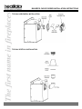
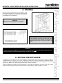
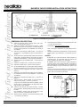
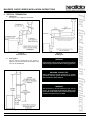
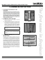
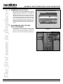
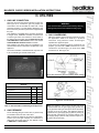
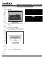
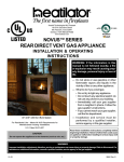
INSTALLATION & OPERATING INSTRUCTIONS BCDV36 BUILDERS CHOICE DIRECT VENT DECORATIVE GAS APPLIANCE WARNING: If the information in this manual is not followed exactly, a fire or explosion may result causing property damage, personal injury or loss of life. Do not store or use gasoline or other flammable vapors and liquids in the vicinity of this or any other appliance. What to do if you smell gas Do not try to light any appliance. Do not touch any electrical switch; do not use any phone in your building. Immediately call your gas supplier from a neighbors phone. Follow the gas suppliers instructions. If you cannot reach your gas supplier, call the fire department. BCDV36 BUILDERS CHOICE U.S. PATENT 5,613,487 Installation and service must be performed by a qualified installer, service agency or the gas supplier. CAUTION: Do not expose the appliance to the elements (such as rain, etc.). WARNING! Improper installation, adjustment, alteration, service or maintenance can cause injury or property damage. Refer to this manual. For assistance or additional information, consult a qualified installer, service agency or the gas supplier. 01-03 1 33606 Rev D BUILDER'S CHOICE SERIES INSTALLATION INSTRUCTIONS Please retain this manual for future reference. CONTENTS A. B. C. D. E. F. G. H. I. J. K. L. M. N. O. P. Q. Appliance Specifications ................................................................................................................................. 3 Nomenclature ................................................................................................................................................. 5 Location and Clearances ................................................................................................................................ 6 Framing .......................................................................................................................................................... 7 Setting the Appliance ..................................................................................................................................... 7 Venting ........................................................................................................................................................... 8 Assembling Vent Sections ........................................................................................................................... 13 Utilities ......................................................................................................................................................... 15 Finishing ....................................................................................................................................................... 17 Appliance Preparation .................................................................................................................................. 18 Lighting Instructions ..................................................................................................................................... 19 Seasonal Checklist ...................................................................................................................................... 20 Fuel Conversion ............................................................................................................................................ 21 Start-up Issues ............................................................................................................................................. 21 Maintenance Instructions .............................................................................................................................. 21 Optional Components ................................................................................................................................... 23 Replacement Parts ....................................................................................................................................... 24 Index ............................................................................................................................................................ 27 Warranty ....................................................................................................................................................... 28 SAFETY PRECAUTIONS 1. Please read these installation instructions completely before beginning installation procedures. Failure to follow them could cause an appliance malfunction resulting in serious injury and/or property damage. 2. Always check your local building codes prior to installation. This installation must comply with all local, regional, state and national codes and regulations. 3. Installation and repair should be done by a qualified service person. This appliance should also be inspected annually by a qualified service person. More frequent inspections/cleaning may be required due to excessive lint from carpeting, bedding materials, etc. It is imperative that the control compartment, burners and circulating air passageways of the appliance be kept clean. 4. This is a vented decorative gas appliance. Do not burn wood or other material in this appliance. 5. NEVER leave children unattended when there is a fire burning in the appliance. 6. This appliance may only use the approved venting systems shown in these installation instructions. Venting must not be connected to chimney flue servicing a solid fuel burning appliance or a gas fuel burning appliance. 7. NEVER use gasoline, gasoline-type lantern fuel, kerosene, charcoal lighter fluid, or similar liquids in this appliance. Keep any flammable liquids a safe distance from the appliance. 8. While servicing this appliance, always shut off all electricity and gas to the appliance. This will prevent possible electrical shock or burns. Also, make sure the appliance is completely cooled before servicing. 9. Do not use this appliance if any part has been under water. Immediately call a qualified service technician to inspect the appliance and to replace any part of the control system and any gas control which has been under water. 10. Be sure to provide adequate clearances around the air openings into the combustion chamber and adequate accessibility clearances for servicing and proper operation. 33606 Rev D 2 01-03 BUILDER'S CHOICE SERIES INSTALLATION INSTRUCTIONS A. APPLIANCE SPECIFICATIONS 1. U.S. AND CANADA CERTIFICATION The Builder's Choice Series Gas Appliance has been tested in accordance with the ANSI standard Z21.50b-1998 and U.L. 307B in the United States; in Canada, the current CAN/CGA-M2.22-M98, and has been LISTED by Underwriters Laboratories Inc. for installation and operation as described in this manual. All components are UL, AGA, CGA or CSA safety certified. 2. LOCAL CODES This installation must conform with local codes. In the absence of local codes, with the National Fuel Gas Code, ANSI Z223.1-latest edition in the U.S.A., and the CAN/CGA B149 Installation Codes in Canada. The Builder's Choice Series gas appliance has been tested and listed for use in manufactured housing (mobile homes). These installation instructions conform with the Home Construction and Safety Standard, Title 24 CFR, Part 3280, or when such a standard is not applicable, the standard for Manufactured Home Installations, ANSI A225.1. If any assistance is required during installation, please contact your local dealer or contact Heatilator Technical Services Department, 1915 W. Saunders Street, Mt. Pleasant, Iowa 52641, 1-800-843-2848. HEATILATOR® is a registered trademark of Heatilator Inc., a Division of Hearth & Home Technologies 3. GLASS CERTIFICATIONS/SPECIFICATIONS Hearth & Home Technologies gas appliances manufactured with tempered glass may be installed in hazardous locations such as bathtub enclosures as defined by the CPSC. The tempered glass has been tested and certified to the requirements of ANSI Z97.1-1984 and CPSC 16 CFR 1202. (Safety Glazing Certification Council SGCC# 1595 and 1597. Architectural Testing, Inc. Reports 02-31919.01 and 02-31917.01). This statement is in compliance with SPCS 16 CFR Section 1201.5 Certification and labeling requirements which refers to 15 USC 2063 stating Such certificate shall accompany the product or shall otherwise be furnished to any distributor or retailer to whom the product is delivered. Some local building codes require the use of tempered glass with permanent marking in such locations. Glass meeting this requirement is available from the factory. Please contact your dealer or distributor to order. WARNING! DO NOT use this appliance if any part has been under water. Immediately call a qualified service technician to inspect the appliance and to replace any part of the control system and any gas control which has been under water. CAUTION: Do not expose the appliance to the elements (such as rain, etc.). Note: Minimum and maximum clearances must be maintained at all times. Illustrations throughout these instructions reflect typical installations and are for design purposes only. Actual installation may vary slightly due to individual design preferences. The illustrations and diagrams used throughout these installation instructions are not drawn to scale. 01-03 Tools and building supplies normally required for installation: Saw Pliers Hammer Phillips screwdriver Tape measure Plumb line Level Safety glasses 3 Wall-finishing materials Framing material Appliance surround Caulking material Safety gloves Framing square Electric drill and bits 33606 Rev D BUILDER'S CHOICE SERIES INSTALLATION INSTRUCTIONS TYPICAL HORIZONTAL INSTALLATION TYPICAL VERTICAL INSTALLATION 33606 Rev D 4 01-03 BUILDER'S CHOICE SERIES INSTALLATION INSTRUCTIONS B. NOMENCLATURE BUILDER'S CHOICE NOMENCLATURE Catalog # Description BCDV - Builders Choice BCDV (no suffix) BCDVL CS Standing pilot, propane gas Direct Vent Cap Shield for horizontal termination only VP-TV Vertical Termination Cap V P 45 45° Elbow FS 6 Firestop Spacer V P 90 90° Elbow VP4 4" Vent Pipe VP6 6" Vent Pipe V P 12 12" Vent Pipe V P 24 24" Vent Pipe V P 36 36" Vent Pipe V P 48 48" Vent Pipe WS6 Wall Heat Shield (to ensure horiztonal clearance) VSS2 Vinyl Soffit Shield RF6 01-03 Standing pilot, natural gas Roof Flashing (vertical termination) - 0/12 to 6/12 pitch VP6-9 6-9" Slip Section VP9-14 9-14" Slip Section VP14-24 14-24" Slip Section VP12MI 12" Vent Section, non-unitized so it can be cut to length VP24MI 24" Vent Section, non-unitized so it can be cut to length VP-TH Horizontal Termination Cap VP-VT1X High Wind Horizontal Termination Cap VP-TB1 Basement Horizontal Termination Cap VP-TRK Rear Vent Horizontal Kit: Cap, Wall Shield, Heat Shield, 6-9" Slip Section VP-TRK2 Rear Vent Horizontal Kit: Cap, Wall Shield, Heat Shield, 4" Vent Section VS4 Vertical Vent Support HS1 Rear Vent Flue Heat Shield 5 33606 Rev D BUILDER'S CHOICE SERIES INSTALLATION INSTRUCTIONS C. LOCATION AND CLEARANCES Dimensions WARNING! Due to high temperatures, the appliance should be located out of traffic and away from furniture and draperies. 1. APPLIANCE LOCATIONS AND SPACE REQUIREMENTS Figure 1 illustrates a variety of ways the appliance may be located in a room. The Builder's Choice Series may be installed directly on the floor or on a hearth. These appliances are certified for installation in a bedroom, bed/sitting room or in mobile homes in the U.S. and Canada. Note: Dimensions represent minimum space required for a centered corner installation. Actual requirements will vary with individual construction. 2. CLEARANCES a. b. For the appliance: Top of standoffs 0 Floor 0 Back of appliance 1/2 Sides 1/2 Front Face to Ceiling 30 Minimum Venting Clearances (see Figure 2). 1) Horizontal runs off of the back of the appliance to the wall shield: 0 above the top of the appliance standoffs 1 sides and bottom of the vent 2) Horizontal runs inside a wall (heat shields must be installed) 3 air space on top of the vent 1 from sides and bottom of vent 3) Vertical runs 1 air space around the vent Figure 1 - Appliance Locations Figure 2 - Rear Vented Appliances Venting Clearances 33606 Rev D 6 01-03 BUILDER'S CHOICE SERIES INSTALLATION INSTRUCTIONS D. FRAMING Figure 3 shows a typical framing of this appliance using combustible materials. Figure 4 shows the mantel heights for mantel projections. All required clearances to combustibles must be adhered to. CAUTION: Wear gloves and safety glasses for protection. * from base of appliance Figure 3 - Framing CAUTION: Provide adequate clearances around the air openings into the combustion chamber and adequate accessibility clearances for servicing and proper operation. Figure 4 - Mantel Height WARNING! To prevent contact with sagging or loose insulation, the appliance must not be installed against vapor barriers or exposed insulation. Localized overheating could occur and a fire could result. E. SETTING THE APPLIANCE This appliance may be placed on a smooth combustible or noncombustible continuous, flat surface. When the appliance is installed directly on carpeting, tile or other combustible material other than wood flooring, the appliance shall be installed on a metal or wood panel extending the full width and depth of the appliance. Slide the appliance into position and level the appliance from side-to-side and front-to-back. Shim as necessary. Secure the appliance by bending out the nailing flanges on each side of the appliance and nail to framing. The nailing flanges have been positioned 5/8 inch back from the front of the appliance to allow the addition of drywall. 01-03 7 33606 Rev D BUILDER'S CHOICE SERIES INSTALLATION INSTRUCTIONS F. VENTING CAUTION: WARNING - RISK OF FIRE! Air space clearances must be maintained at all times. WARNING - RISK OF FIRE! The horizontal run of vent must have a 1/4 rise for every 1 ft. of run towards the termination. Never allow the vent to run downward. This could cause high temperatures and may present a fire hazard. Provisions shall be made to provide adequate combustion and ventilation air. WARNING - RISK OF FIRE! If you have chosen horizontal termination, be sure there are no present nor future obstructions from trees, bushes, snow drifts, etc. Use only pipe supplied and listed for use with this appliance. See page 5 for a description of the listed components. See the directions on page 13 for assembling vent sections. 1. HORIZONTAL TERMINATION a. b. Installing the Interior Wall Shield Frame a hole in a combustible wall for an interior wall shield as shown in Figure 5. This shield maintains minimum clearances and prevents cold air infiltration. Termination Vent termination must not be recessed in the wall. Siding may be brought to the edge of the cap. Install the cap as shown in Figure 6. The cap pipe sections should overlap the vent pipe by 1-1/2. Caulk the outside edges of the cap. Local codes may require the installation of a shield (product #CS) which prevents the cap from accidentally touching anything or anyone. Figure 11 illustrates cap locations prescribed by current ANSI Z273.1 and CAN/CGA-B149 Installation Codes. The termination cap height must meet all local and national codes and not be easily blocked or obstructed. If the hole being penetrated is of noncombustible materials, a 9 diameter hole is acceptable. Figure 5 Interior Wall Shield Figure 6 Venting Through the Wall 33606 Rev D 8 01-03 BUILDER'S CHOICE SERIES INSTALLATION INSTRUCTIONS c. No Elbows The maximum horizontal run with no vertical sections of vent is 18 from the back of the appliance to the base of the cap. See Figure 7. e. Figure 7 Rear Vented Appliances d. Two Elbows Figure 9 shows various venting configurations using two elbows to terminate horizontally. The maximum vertical run is 20 and the maximum horizontal run is 14. Figure 9 Two Elbows A 45° Elbow For corner venting, a maximum of one 45° elbow may be used. The maximum horizontal run following the elbow is 12 to the base of the cap. See Figure 8. f. Three Elbows - One Elbow Horizontal Figure 10 shows various venting configurations using three elbows to terminate horizontally. The maximum vertical run is 20 and the maximum horizontal run is 12. Figure 8 One 45° Elbow Figure 10 Three Elbows 01-03 9 33606 Rev D BUILDER'S CHOICE SERIES INSTALLATION INSTRUCTIONS Figure 11 - Termination Cap Locations DIMENSION DESCRIPTIONS A Clearance above the ground, a veranda, porch, deck or balcony - 12 inches (30 cm) minimum. * O Horizontal clearance between two horizontal termination caps 12 inches (30 cm) minimum. B Clearance to window or door that may be opened 10,000 BTUs or less, 6 inches (15 cm) minimum; 10,000-50,000 BTUs, 9 inches (23 cm) minimum; over 50,000 BTUs, 12 inches (30 cm) minimum. * * As specified in CGA B149 Installation Codes C Clearance to permanently closed window 12 inches (30 cm) minimum - recommended to prevent condensation on window. ** D Vertical clearance to ventilated soffit located above the termination within a horizontal distance of 2 feet (60 cm) from the centerline of the termination 18 inches (46 cm) minimum. ** WARNING! E Vertical clearance to unventilated soffit - 12 inches (30 cm) minimum. ** F Clearance to outside corner - 6 inches (15 cm) minimum. G Clearance to inside corner - 6 inches (15 cm) minimum. H Not to be installed above a meter/regulator assembly within 3 feet (90 cm) horizontally* from the center line of the regulator I Clearance to service regulator vent outlet - 6 feet (1.8m) minimum. * J Clearance to non-mechanical air supply inlet into building or the combustion air inlet to any other appliance - 12 inches (30 cm) minimum. * K Clearance to mechanical air supply inlet - 6 feet (1.8 m) minimum. * L Clearance above a paved sidewalk or paved driveway located on public property - 7 feet (2.1 m) minimum. Note: Local codes or regulations may require different clearances. Clearance required to vinyl soffit material 30 inches (76 cm) minimum. With a vinyl soffit shield 18 inches (46 cm) minimum. In the U.S.: Vent system termination is NOT permitted in screened porches. You must follow side wall, overhang and ground clearances as stated in the instructions. In Canada: Vent system termination is NOT permitted in screened porches. Vent system termination is permitted in porch areas with two or more sides open. You must follow all side wall, overhang and ground clearances as stated in the instructions. Hearth & Home Technologies assumes no responsibility for the improper performance of the appliance when the venting system does not meet these requirements. A vent may not terminate directly above a sidewalk or paved driveway which is located between two single family dwellings and serves both dwellings. M Clearance under veranda, porch, deck or balcony - 12 inches (30 cm) minimum. * Recommended 30 inches (76 cm) for vinyl or plastic. Only permitted if veranda, porch, deck or balcony is fully open on a minimum of 2 sides beneath the floor. * N Vertical clearance between two horizontal termination caps 12 inches (30 cm) minimum. Figure 12 - Cap Clearances 33606 Rev D 10 01-03 BUILDER'S CHOICE SERIES INSTALLATION INSTRUCTIONS 2. VERTICAL TERMINATION a. Clearances See Figure 13 for clearance information. Figure 15 Vent Support Figure 13 Vent Clearances b. Vent Lengths Various venting configurations are shown in Figures 14 and 15 from which the maximum vent runs can be determined. WARNING! A gas appliance must not be connected to a chimney flue servicing a separate solid fuel burning appliance. WARNING - RISK OF FIRE! Always maintain minimum clearances or greater around the chimney system. Do not pack air spaces with insulation or other material. WARNING! The horizontal run of vent must have a 1/4 rise for every 1 of run towards the termination. Never allow the vent to run downward. This could cause high temperatures and present a fire hazard. Figure 14 - Vent Lengths 01-03 11 33606 Rev D BUILDER'S CHOICE SERIES INSTALLATION INSTRUCTIONS c. Firestop Spacer/Chimney Installation Frame an opening and install an FS6 Firestop Spacer whenever the vent penetrates a ceiling/ floor area, as shown in Figure 16. Frame the opening with the same sized lumber as used in the ceiling/floor joists. Do not pack insulation around the chimney. d. Chase/Termination Installation Figures 17 and 18, and Table 1 specify minimum chimney heights for various pitched roofs. These chimney heights are necessary for safety and do not ensure draft-free operation. Trees, buildings, adjoining roof lines, adverse conditions, etc. may create a need for a taller chimney should down drafting occur. Figure 17 Chimney Height for Vertical Termination Figure 16 Installing the Firestop Spacer Roof Pitch Flat to 6/12 6/12 to 7/12 Over 7/12 to 8/12 Over 8/12 to 9/12 Over 9/12 to 10/12 Over 10/12 to 11/12 Over 11/12 to 12/12 Over 12/12 to 14/12 Over 14/12 to 16/12 Over 16/12 to 18/12 Over 18/12 to 20/12 Over 20/12 to 21/12 H (Min.) Ft. 1.0 1.25 1.5 2.0 2.5 3.25 4.0 5.0 6.0 7.0 7.5 8.0 Table 1 Chimney Height 33606 Rev D Figure 18 Multiple Vertical Termination Clearances Note: To ensure proper operation, verify all venting and the termination are unobstructed. 12 01-03 BUILDER'S CHOICE SERIES INSTALLATION INSTRUCTIONS G. ASSEMBLING VENT SECTIONS 1. ATTACHING THE VENTING TO THE APPLIANCE To attach the first VP section to the appliance collars, simply slide the flared end of the inner vent of the VP section over the inner collar on the appliance. At the same time, insert the outer vent into the outer collar on the appliance. Push the vent section into the appliance collar until all the lances have snapped in place. Tug slightly on the vent to confirm it has completely locked into place. 2. ASSEMBLING VENT SECTIONS a. b. Start the flared inner flue of section A over the inner flue of section B. Insert the outer flue of section A into the outer flue of section B. See Figure 19. Once both inner and outer flues are started, press section A into section B firmly until all lances have snapped into place. Tug slightly on section A to confirm it has completely locked into place. See Figure 20. Figure 19 Note: Squeezing the pipe slightly to fit may be necessary. Note: Make sure that the seams are not per- fectly aligned to prevent unintentional disconnection. Figure 20 3. ASSEMBLING MINIMUM INSTALLATIONS (MI) SECTIONS MI sections are non-unitized so that they can be cut to a certain length. To use these sections, they must be cut to length from the non-expanded end. See Figure 21. They can then be attached by first connecting the expanded end of the MI inner vent with the inner vent from the adjacent vent section and securing with three screws. The expanded portion of the MI inner vent must overlap completely with the untreated end of the adjacent vent section. The outer vent can then be inserted into the adjacent outer vent expanded end and attached to the next vent section with three screws. The other end of the MI vent section can then be attached by fitting a snap lock section to it and snapping it together as normal. 01-03 Figure 21 13 33606 Rev D BUILDER'S CHOICE SERIES INSTALLATION INSTRUCTIONS 4. ASSEMBLING SLIP SECTIONS Slip sections should be snapped into the first mating piece, then expanded to their desired length, making sure that a 1.5 overlap is maintained between the two sections of the slip section. The two sections of the slip section then need to be secured by driving two screws through the overlapping portions of the outer vent. See Figure 22. This will secure the slip section to the desired length and prevent it from separating. The slip section can then be attached to the next section of vent. 5. DISASSEMBLING VENT SECTIONS (ONLY IF NECESSARY) To disassemble any two pieces of pipe, rotate either section so that the seams on both pipe sections are perfectly aligned as shown in Figure 23. They can then be carefully pulled apart. Figure 22 Figure 23 33606 Rev D 14 01-03 BUILDER'S CHOICE SERIES INSTALLATION INSTRUCTIONS H. UTILITIES 1. GAS LINE CONNECTION Open the control access panel as shown in Figure 24. See Figure 25 to connect the gas line properly. All connections must be checked for leaks with a soap and water solution or a leak detector. Bleed the gas line to extract any air that may have been trapped inside the pipe. This appliance is supplied with a 3/8 flare connection to the gas valve. Installation of flexible connector and/ or manual gas valve must conform to local codes. In the absence of local codes, with the National Flue Gas Code ANSI Z223.1-latest edition in the U.S.A. and the CAN/CGA B149 Installation Codes in Canada. This appliance has been tested for installation of a manual shutoff valve in the bottom compartment of the appliance. The Commonwealth of Massachusetts requires this to be a T-handle type manual shutoff valve. WARNING! This valve has been preset at the factory. Altering settings may result in fire hazard or bodily injury. 3. GAS CONVERSIONS Natural or propane gas conversions necessary to meet the application need to be made by a qualified technician using Hearth & Home Technologies specified and approved parts. In the event your appliance must be converted to use propane, you must use a CKP Conversion Kit. To be converted to use natural gas, you must use a CKN Conversion Kit. See Figure 26. (Right Side) Optional: Seal around the gas line to prevent cold air leakage. Figure 25 - Gas Line Figure 24 - Control Access Panel B C D V 36 N.G. L.P. Minimum Inlet Pressure for Purpose of Input Adjustment 4.5* 11* Maximum Inlet Pressure 10.5* 14* Optimal Manifold Pressure 3.5* 10* Minimum Manifold Pressure 1.7* 5.4* Maximum Input BTU/H 20,000 18,500 Orifice Size - Inches 0.089 0.052 * Inches of Water Column Table 2 - Gas Information for Standing Pilot Appliances 2. GAS PRESSURE On the standing pilot gas control valve, a pressure tap is included on the front face of the valve. Table 2 shows the optimum gas pressure information. Consult your local gas company for assistance in determining the proper orifice for your altitude or refer to ANSI Z223.1 - latest edition. 01-03 Figure 26 - Conversion Kit Note: This appliance and its manual shutoff valve must be disconnected from the gas supply piping system during any pressure testing of that system at test pressures in excess of 1/2 psi (3.5 kPa). The appliance must be isolated from the gas supply piping system by closing its manual shutoff valve during any pressure testing of the gas supply piping system at test pressures equal to or less than 1/2 psi (3.5 kPa). 15 33606 Rev D BUILDER'S CHOICE SERIES INSTALLATION INSTRUCTIONS 4. WIRING Standing Pilot Ignition - Millivolt System a. Appliance Requirements A wiring diagram is shown in Figure 27. b. Wall Switch The installer shall supply UL or in Canada, CSAlisted wall switch and wiring between appliance and wall switch. This appliance was tested with eighteen feet of UL Listed 18 ga. Type CL2 105°C, two conductor thermostat wire. If other wiring materials are used they shall comply with local codes or in the absence of local codes, with National Electrical Code ANSI/NFPA 70-latest edition or Canadian Electrical Code CSA C22.1. c. Optional Accessories Requirements Wiring for optional accessories should be done now to avoid reconstruction. Note: This appliance must be electrically wired and grounded in accordance with local codes. In the absence of local codes, the wiring must comply with the National Electric Code ANSI/NFPA 70 - latest edition or the Canadian Electric Code CSA C22.1. WARNING! This standing pilot appliance does not require a 110V AC power supply for operation. Connecting the appliance/wall switch to a 110V AC will cause the appliance to malfunction and destroy the valve and thermopile. 5. JUNCTION BOX INSTALLATION AND WIRING Refer to the installation instructions included with the JK9 Junction Box Kit and the insert of Figure 27. Detailed picture of the Junction Box (Optional for Standing Pilot Appliances). 14-3 with Ground Romex is the recommended wiring to the appliance Junction Box. Figure 27 Standing Pilot Ignition Wiring Diagram 33606 Rev D 16 01-03 BUILDER'S CHOICE SERIES INSTALLATION INSTRUCTIONS I. FINISHING 1. COMBUSTIBLE FINISHING MATERIAL Materials made of or surfaced with wood, compressed paper, plant fibers, plastics, or any material capable of igniting and burning, whether flame proofed or not, plastered or unplastered (this includes drywall) are considered to be combustible. 2. NONCOMBUSTIBLE FINISHING MATERIAL Material which will not ignite and burn. Such materials are those consisting entirely of steel, iron, brick, tile, concrete, slate, glass or plasters, or combination thereof, or have a UL Fire rating of Zero (0). 3. HIGH TEMPERATURE SEALANT MATERIAL Sealants that will withstand high temperatures: General Electric RTV103 (Black) or equivalent; Rutland, Inc. Appliance Mortar #63 or equivalent. A high temperature sealant, 1/8 wide minimum, must be used to close off gaps between the appliance and facing to prevent cold air leaks. See Figure 28. Figure 28 Finishing Materials 4. ATTACHING THE HOOD The hood must be attached or a fire hazard may result. Simply slide the hood under the three screws above the appliance opening. See Figure 29. 5. GLASS AND SCREEN REMOVAL See page 22 of this manual. WARNING! Grilles and hoods on this appliance cannot, in any way, be covered as it may create a fire hazard. Figure 29 Hood Placement 01-03 17 33606 Rev D BUILDER'S CHOICE SERIES INSTALLATION INSTRUCTIONS J. APPLIANCE PREPARATION 1. LOG SET The log set should look similar to that in Figure 30. WARNING! RISK OF CARBON MONOXIDE! Never operate this appliance with the glass removed or not sealed. WARNING! RISK OF CARBON MONOXIDE! Do not hit or strike the glass. Do not operate this appliance if the glass if broken or cracked. Figure 30 BCDV36 Gas Log Set 2. PLACING THE VERMICULITE AND LAVA ROCK See Figure 31. 3. PLACING THE ROCK WOOL Place a small amount of 1/2 diameter pieces (dime sized) of rock wool on the ember tray above the burner Figure 31 Placing the Rock Wool (top logs removed for clarity) tube. This will provide a glowing ember look to the appliance when burning. See Figure 31. 4. GLASS AND SCREEN REPLACEMENT See page 22 of this manual. 33606 Rev D 18 01-03 BUILDER'S CHOICE SERIES INSTALLATION INSTRUCTIONS K. LIGHTING INSTRUCTIONS FOR YOUR SAFETY READ BEFORE LIGHTING WARNING! If you do not follow these instructions exactly, a fire or explosion may result causing property damage, personal injury or loss of life. A. This appliance has a pilot which must be lighted by hand. When lighting the pilot, follow these instructions exactly. B. BEFORE LIGHTING smell all around the appliance area for gas. Be sure to smell next to the floor because some gas is heavier than air and will settle on the floor. C. Use only your hand to push in or turn knob. Never use tools. If the knob will not push in or turn by hand, dont try to repair it; call a qualified service technician. Force or attempted repair may result in a fire or explosion. D. Do not use this appliance if any part has been under water. Immediately call a qualified service technician to inspect the appliance and to replace any part of the control system and any gas control which as been under water. WHAT TO DO IF YOU SMELL GAS Do not try to light any appliance. Do not touch any electric switch; do not use any phone in your building. Immediately call your gas supplier from a neighbors phone. Follow the suppliers instructions. If you cannot reach your gas supplier, call the fire department. LIGHTING INSTRUCTIONS STOP! Read the safety information above on this label! 1. Turn off all wall switches to the appliance or remote. 2. Open the control access panel. 3 Turn gas line to CLOSED. Wait 5 minutes to clear out any gas. Then smell for gas, including near the floor. If you smell gas, STOP! Follow B in the safety information above on this label. If you dont smell gas, go to the next step. 4 Turn gas line valve to OPEN. 5 Turn pilot knob clockwise to OFF (knob may have to be depressed to pass the PILOT position). 6 Locate pilot assembly inside appliance. 7 Locate red ignitor button in the bottom of the appliance. 8 Turn pilot knob to PILOT and push in. 9. Continue to hold in pilot knob and push the red ignitor button 12-15 times until small blue pilot flame appears. 10. Continue to hold in pilot knob for approximately one minute. Pilot should remain lit. If pilot goes out, wait 5 minutes and repeat Steps 4-9. 11 Release and turn the knob counterclockwise to ON. Turn the wall switch to ON to light the main burner. Do not light by hand! 12. If the appliance will not operate, follow the instructions To Turn Off Gas To Appliance and call your service technician or gas supplier. 01-03 TO TURN OFF THE GAS TO THE APPLIANCE 1. 2. 3. 4. Turn off the wall switch or set thermostat to lowest setting. Close the control access panel. Turn gas line to CLOSED position. Do not force. Close control access panel. 19 33606 Rev D BUILDER'S CHOICE SERIES INSTALLATION INSTRUCTIONS WARNING! Children and adults should be alerted to the hazards of high surface temperatures and should stay away to avoid burns or clothing ignition. Young children should be carefully supervised when they are in the same room as the appliance. CAUTION: Any safety screen or guard removed for servicing an appliance must be replaced prior to operating this appliance. Clothing or other flammable material should not be placed on or near the appliance. L. SEASONAL CHECKLIST Note: Installation and repair should be done by a qualified service person. The appliance should be inspected before use and at least annually by a qualified service person. More frequent cleaning may be required due to excessive lint from carpeting, bedding material, etc. It is imperative that control compartments, burners and circulating air passageways of the appliance be kept clean. 1. PRIOR TO OPERATION WARNING! Do not use this appliance if any part has been under water. Immediately call a qualified service technician to inspect the appliance and to replace any part of the control system and any gas control which has been under water. 2. STANDING PILOT OPERATION Before operating this appliance, have a qualified technician: a. Review proper placement of logs, rock wool and vermiculite. b. Check wiring. c. Ensure there are no gas leaks. d. Ensure the glass is sealed and in proper position. e. Ensure the flow of combustion and ventilation air is not obstructed. f. Check the air shutter adjustment. WARNING! Hearth & Home Technologies recommends you leave the pilot on year round. a. Lighting the Appliance During Regular Use Turn the wall switch to ON. b. Shutdown During Regular Use Turn the wall switch to OFF. c. If you decide to shut down the appliance for a long period of time: 1) Turn all wall switches to OFF (if applicable). 2) Turn pilot knob on valve to OFF. 3) Turn the gas line valve to CLOSED. 4) To relight the appliance, see page 19. Keep the area near the appliance clear and free from combustible materials, Gasoline and other flammable vapors and liquids. 33606 Rev D 20 01-03 BUILDER'S CHOICE SERIES INSTALLATION INSTRUCTIONS M. FUEL CONVERSION Do not burn wood or other material in this appliance. Natural or propane gas conversions necessary to meet the application need to be made by a qualified technician using Hearth & Home Technologies specified and approved parts. In the event your appliance must be converted to use propane, you must use a CKP Conversion Kit. To be converted to use natural gas, you must use a CKN Conversion Kit. See Figure 26. N. START-UP ISSUES Issue Causes and Possible Solutions 1. Condensati on on the glass: Thi s i s a result of gas combusti on and temperature vari ati ons. As the appli ance warms, thi s condensati on should di sappear. 2. Blue flames: Thi s i s a result of normal operati on and the flames wi ll begi n to yellow as the appli ance i s allowed to burn. 3. Odor from the appli ance: When fi rst operated, thi s appli ance may release an odor for the fi rst several hours. Thi s i s caused by the curi ng of the pai nt and the burni ng off any any oi ls remai ni ng from manufacturi ng. 4. Fi lm on the glass: Thi s i s a normal result of the curi ng process of the pai nt and logs. If the glass i s not cleaned wi thi n 4-6 hours of i ni ti al burni ng, thi s may requi re a nonabrasi ve cleaner to remove, such as Brasso. WARNING! Never use gasoline, gasoline-type lantern fuel, kerosene, charcoal lighter fluid or similar liquids in this appliance. Keep any flammable liquids a safe distance from the appliance. O. MAINTENANCE INSTRUCTIONS 1. CLEANING THE BURNER AND CONTROL COMPARTMENT Keep the control compartment clean by brushing and vacuuming at least once a year. Failure to do so may shorten the life of the components. Always turn off the wall switch (or remote control) and gas valve before cleaning. Failure to do so may shorten the life of the components. 2. CHECKING FLAME PATTERNS Check the flame of the burner periodically, making sure the flames are steady, not lifting or floating. The flame color should be blue with yellow tips. The thermopile and thermocouple tips should be covered with flame. See Figure 32. If the vent configuration is installed incorrectly, the venting may cause the flames inside the appliance to lift or ghost, which is a dangerous situation. Inspect the flames after installation to ensure proper performance. See Figure 33. If the vent configuration is correct, yet the flames are lifting or ghosting, shut off the gas to the appliance and contact the dealer. 3. VENTING SYSTEM INSPECTION The appliance and venting system should be inspected before use and at least annually by a qualified field service person to ensure that the flow of combustion and ventilation air is not obstructed. Flame covers top 1/2 of thermopile and thermocouple. Figure 32 - Standing Pilot 01-03 Figure 33 - Flame Patterns 21 33606 Rev D BUILDER'S CHOICE SERIES INSTALLATION INSTRUCTIONS 4. CLEANING THE GLASS See Figure 34. Never operate this appliance without the glass properly secured in place or if the glass is broken or chipped. In the event of glass breakage, carefully remove the glass frame. This will allow the removal of all glass fragments and sheet metal edge protection strips. Vacuum all remaining glass pieces with a shop vac. DO NOT VACUUM IF PIECES ARE HOT! Replace glass only with a Heatilator glass panel assembly through your local distributor. Never use substitute material. Only fully tempered soda lime safety glass or ceramic glass may be used on this appliance. 6. To replace the glass, ensure the glass bottom is set completely down in the bottom retainer and replace the two Quick Access Latches to the secure position. 1. Lift and pull out upper grille and control access panel. 2. Lift and pull out the bottom of the screen, then pull down out of top corner retainers. 3. Pull and release the two Quick Access Latches using handle provided and stored in valve compartment. 7. To replace the screen, place the top of the screen in the two corner catches. Raise the screen until it clears the bottom retainer, then lower into position. 4. Angle top of glass out and remove from the lower retainer. 8. Replace Quick Access Latch handle in its clips on the lower corner behind the grille. 5. Set the glass safely on a nonabrasive surface. Clean using a mild, nonabrasive cleaning solution (i.e. Brasso). 9. Replace the upper grille and control access panel. Safety Note: Figure 34 Glass Cleaning Quick Access Latch Handle glass with care to avoid striking, scratching or slamming shut. Never clean glass when hot. Keep children and pets a safe distance away. 5. LOG REMOVAL/REPLACEMENT If removal of the logs becomes necessary, remove the two screws at each side of the front log. Grasp the front log. Pull the log toward the front and up, off the burner. See Figure 35. To replace the logs, grasp the front log. Lower the log set so that the back log rests on the shelf in the back of the appliance and the two tabs behind the back log are inserted into the slots in the back of the firebox. Replace the two screws removed earlier at each end of the front log. Figure 35 - Log Removal 33606 Rev D 22 01-03 BUILDER'S CHOICE SERIES INSTALLATION INSTRUCTIONS P. OPTIONAL COMPONENTS Contact your local Heatilator Dealer by calling: 1-800-843-2848. MF1, MF2 High/Low Flame Adjustment BC10 Fan Motor Rheostat Control RC-SMART-HTL Remote Control JK9 Junction Box Kit FK4 Fan Kit RC-BATT-HTL Battery-operated (standing pilot) Remote Control RC-SMART-BATT-HTL Battey-operated Remote Control with Thermostat Control RC-SMART-STAT-HTL Remote Control with Thermostat Control 01-03 FK160 Fan Kit 23 33606 Rev D BUILDER'S CHOICE SERIES INSTALLATION INSTRUCTIONS HOMEOWNERS NOTES 01-03 25 33606 Rev D BUILDER'S CHOICE SERIES INSTALLATION INSTRUCTIONS HOMEOWNERS NOTES 33606 Rev D 26 01-03 BUILDER'S CHOICE SERIES INSTALLATION INSTRUCTIONS Index A G Q Access Panel 15 Air Shutter Adjustment 20 Appliance Preparation 18 Gas Conversions 15 Pressure 15 To turn off 19 Gas Codes 3, 15 Gas Conversions 21 Gas Leaks 20 Gas Line connection 15 Gas Log Assembly 24 Gas Log Set 18 Glass 17, 18, 20 Certifications/Specifications 3 Quick Access Latch 22 B Bathtub Areas 3 BC10 23 BTUs 15 Building Codes 3, 8 Burner 21 C Cap Clearances 10 Carbon Monoxide 18 Certification 3 Chase Installation 12 Chimney Height 12 Chimney Height for Vertical Termination 12 Chimney Installation 12 Clearances 3, 6, 7, 8 Cap 10 Minimum Venting 6 Vertical Termination 11 Codes Building 3, 8 Electric 16 Gas 3, 15 Manufactured Housing 3 Combustible Material 17 Control Compartment 21 Conversion Kits 15 Conversions 15 Gas 21 H Hood 17 Horizontal Termination 8 I Input Rate 15 Interior Wall Shield 8 Junction Box 16, 23 L Lava Rock 18 Lighting Instructions 19 Local Codes 3 Location and Clearances 6 Log Removal/Replacement 22 Log Set 18 M Elbows 45° 9 None 9 Two 9 Electric Codes 16 F N Fan Kit 23 Fan Motor Rheostat Control 23 Finishing 17 Firestop Spacer 12 Flame Patterns 21 Framing 7 Fuel 15, 21 Fuel Conversions 15 Nomenclature 5 Noncombustible Material 17 01-03 Remote Control 23 Replacement Parts 24 Rock Wool 18 S Screen 17 Sealant Material 17 Seasonal Checklist 20 Shutdown 20 Slip Sections 14 Space Requirements 6 Standing Pilot 21 Standing Pilot Ignition 16 Standing Pilot Operation 20 Standing Pilot Wiring Diagram 16 Start-up Issues 21 T J Maintenance Instructions 21 Mantel 7 Manufactured Housing Codes 3 Massachusetts 15 MF1 23 Minimum Installations 13 Multiple Vertical Termination 12 E R O Obstructions 8 Optional Components 23 Termination Horizontal 8 Termination Cap Locations 10 Termination Installation 12 Typical Horizontal Installation 4 Typical Vertical Installation 4 U Utilities 15 V Vent Support 11 Venting 8 Disassembly 14 MI Sections 13 Slip Section Assembly 14 System Inspection 21 Venting Through the Wall 8 Vermiculite 18 Vertical Termination 11 Chase Installation 12 Chimney Height 12 Clearances 11, 12 Firestop Spacer/Chimney Installation 12 Vent Lengths 11 Vent Support 11 W Wall Switch 16 Water 3 Wiring 16 27 33606 Rev D Gas Appliance (Fireplace) Limited Lifetime Warranty HEARTH & HOME TECHNOLOGIES (HHT) extends the following warranty for HEATILATORâ gas appliances installed in the United States of America or Canada (the Appliance). Dealers and employees of HHT have no authority to make any warranty or authorize any remedies in addition to or inconsistent with the terms of this warranty. Limited Lifetime Warranty HHT warrants the Appliance for component failure due to a manufacturing defect of any of the following components: combustion chamber, burner pan, and logs. The Limited Lifetime Warranty specified above is subject to the conditions, exclusions and limitations listed below, is for the period the Appliance is owned by the original homeowner only, and is nontransferable. 1 Year Limited Warranty HHT warrants the Appliance to be free from failure of any of the following components for a period of one year after installation: valve, flexible gas line connector, glass panel, fan, direct vent chimney components, factory paint, gasket, piezo ignitor, thermopile, thermocouple, junction box, pilot assembly, shutoff valve, high limit switch, refractory liners, transformer, and control box. If the Heatilator Appliance is found to be defective in either material or workmanship within one year of the date of original installation, HHT will provide replacement parts at no charge and pay reasonable labor and freight costs, and is for the period of one year following the date of original installation of the Appliance. Conditions, Exclusions, & Limitations of Liability A. B. C. D. Both the Limited Lifetime and 1 Year Limited Warranties supplied by HHT apply only while the Appliance is in its location of original installation. HHTs obligation under this warranty does not extend to damages resulting from (1) installation, operation or maintenance of the Appliance not in accordance with the Installation Instructions, Operating Instructions, and the Listing Agent Identification Label furnished with the Appliance; (2) installation which does not comply with local building codes; (3) shipping, improper handling, improper operation, abuse, misuse, accident or unworkmanlike repairs; (4) environmental conditions, inadequate ventilation or drafting caused by tight sealing construction of the structure, air handling devices such as exhaust fans or forced air furnaces, or other causes; (5) use of fuels other than those specified in the Operating Instructions; (6) installation or use of components not supplied with the Appliance or any other components not expressly authorized and approved by HHT; and/or (7) modification of the Appliance not expressly authorized and approved by HHT in writing. This warranty is limited to only the component parts manufactured or supplied by HHT. HHTs liability under both the Limited Lifetime Warranty and the 1 Year Limited Warranty is limited to the replacement and repair of defective components or workmanship during the applicable period. HHT may fully discharge all of its obligations under such warranties by repairing the defective component(s) or at HHTs discretion, providing replacement parts at no charge and paying reasonable labor and freight costs. EXCEPT TO THE EXTENT PROVIDED BY LAW, HHT MAKES NO EXPRESS WARRANTIES OTHER THAN THE WARRANTY SPECIFIED HEREIN. THE DURATION OF ANY IMPLIED WARRANTY IS LIMITED TO DURATION OF THE WARRANTY SPECIFIED ABOVE. Some states do not allow exclusions or limitations of incidental or consequential damages, so those limitations may not apply to you. This warranty gives you specific rights; you may also have other rights which vary from state to state. How to Obtain Service To obtain service under this warranty you must: 1. Send written notice of the claimed condition to Heatilator Technical Service Department, Hearth & Home Technologies, 1915 W. Saunders Street, Mt. Pleasant, Iowa 52641-1563. You may also register your claim online at www.heatilator.com/contact.asp. 2. Provide proof of purchase, model number, serial number, and manufacturing date code to HHT. 3. Provide HHT reasonable opportunity to investigate the claim, including reasonable opportunity to inspect the Appliance prior to any repair or replacement work and before the Appliance or any component of the Appliance has been removed from the place of original installation. 4. Obtain HHTs consent to any warranty work before the work is done. ADDITIONAL INFORMATION. If you would like information on current HEATILATOR products or want to locate a dealer in your area, call 1-800-843-2848. ã2001 Heatilatorâ is a Registered Trademark of Hearth & Home Technologies 30532 Rev D 28 01-03