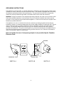
1
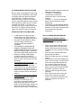
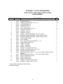
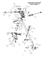
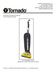
TORNADO INDUSTRIES
7401 W. LAWRENCE AVENUE
CHICAGO, IL 60706
(708) 867-5100 FAX (708) 867-6968
www.tornadovac.com
Tornado
â
Operation & Maintenance Manual
For Commercial Use Only
The DS Series of 175 RPM Floor Maintenance Machines
MODEL NOS.
97580, 97580C, 97585 & 97585C (115V, 60Hz)
97581 & 97586 (230V, 50Hz)
L7580AD 03/01 ã2001 Tornado All rights reserved.
1
NOTES
2
This instruction book covers:
CATALOG NO.
SERIES
SIZE
97580
D
17” (43cm)
Steel base
97580C
A
17” (43cm)
Steel base
1-1/2
115V
6
Optional
1-1/2
115V
6
Optional
97581
D
17” (43cm)
Steel
base
1-1/2
230V
3
Optional
*
**
CE pending
97585
D
20” (51cm)
Steel base
97585C
A
20” (51cm)
Steel base
1-1/2
115V
7
Optional
1-1/2
115V
7
Optional
97586
D
20” (51cm)
Steel
base
1-1/2
230V
3.5
Optional
*
**
CE pending
HORSE POWER
VOLTS
AMPS
MANUAL
SOLUTION
TANK
CERTIFICATION
CATALOG NO.
SERIES
SIZE
HORSE POWER
VOLTS
AMPS
MANUAL
SOLUTION
TANK
CERTIFICATION
*
**
*This product conforms to ANSI/UL Standard 561.
**This product is certified to CAN/CSA Standard C22.2 No. 10.
All specifications are subject to change without notice.
3
TABLE OF CONTENTS:
Warranty Instructions…………………………….. 4
Safety Instructions…………………………………5
Grounding Instructions…………………………… 6
General Instructions……………………………… 7
1-1/2 HP Base Exploded View………………… 10
1-1/2 HP Base Parts List………………………..11
Handle Exploded View…………………………. 12
Handle Parts List…………………………………13
Handle Exploded View (Canada)………………14
Handle Parts List (Canada)……………………. 15
Optional Attachments & Wiring Diagrams…….16
Tornado® Standard Warranty Program*
10 Years:
Warranties do not cover
components subject to normal
wear or abuse and misuse, and
have other limitations not
specified here. For full details ,
contact your Authorized Tornado
Distributor, Service Center, or the
Tornado Technical Service
Department.
All plastic tanks and rotationally-molded bodies
2 Years:
Parts on all Tornado and Tornado/Karcher cleaning
equipment 1) 2)
1 Year:
Labor on all Tornado and Tornado/Karcher cleaning
equipment 1) 2)
1 Year:
Warranty on batteries, one full year, not pro-rated.
st
* Effective January 1 , 2001. Terms subject to change without notice.
1) Windshear™ Blower-Dryer, Insulation Blowers, CW 50, CW 100, and Duo-Upright Carpetkeepers™
are warranted for 1 (one) year for parts and labor.
2) Warranties on the ICC1, KMR 1200, KMR 1250, and KMR 1700 are 24 months parts/6 months labor
OR 1000 hours of operation, whichever comes first. Warranties on the BR and BD 1000 are 24
months parts/12 months labor OR 1000 hours of operation, whichever comes first.
4
IMPORTANT SAFETY INSTRUCTIONS
FOR COMMERCIAL USE
WHEN USING AN ELECTRICAL APPLIANCE, BASIC PRECAUTIONS SHOULD
ALWAYS BE FOLLOWED INCLUDING THE FOLLOWING:
READ ALL INSTRUCTIONS BEFORE USING THIS MACHINE
WARNING: TO REDUCE THE RISK OF FIRE, ELECTRIC SHOCK, OR INJURY:
Do not leave machine unattended when plugged in. Unplug from outlet when not in use and before changing
pads or attempting any maintenance or adjustment. If handle switch lever is activated accidentally, high
starting torque will cause machine to move and may cause damage or injury.
To avoid electrical shock, Use indoors only. Do not use outdoors and do not expose to rain.
Do not allow to be used as a toy. Close attention is necessary when used by or near children.
Use only as described in this manual. Use only manufacturer’s recommended attachments.
Do not use with damaged cord or plug. If machine is not working properly, if it was dropped, damaged, left
outdoors, or dropped into water, return it to a service center.
Do not pull or carry by cord, use cord as a handle, close a door on cord, or pull cord around sharp edges or
corners. Do not run machine over cord. Keep cord away from heated surfaces. Do not unplug by pulling on
cord. To unplug, grasp the plug not the cord. Do not handle plug or machine with wet hands.
Keep hair, loose clothing, fingers, and all parts of body away from openings and moving parts.
Turn off all controls before unplugging.
Connect to a properly grounded outlet only. See Grounding Instructions.
Do not put hands under base - rotating parts could cause injury. Always keep hands feet and loose fitting
clothing away from moving parts to prevent possible injuries. Use care to keep electrical supply cable from
contacting moving parts, such as floor brushes or pads.
Risk of explosion: Floor sanding can result in explosive mixture of fine dust and air. Use this machine only
in a well-ventilated area, free from any flame or match. Do not use machine in areas where flammable
and/or explosive vapors or dusts are present. To avoid fires do not use with a flammable or combustible
liquid to clean a floor.
Make sure voltage and frequency at the wall receptacle correspond with that indicated on nameplate before
plugging in machine. A 20-amp circuit is recommended. Right or left switch levers will independently
operate the motor.
Never use a device to lock the switch lever in the “ON” position.
Use only a 12 Ga. three-wire extension cable, which have 3-prong grounding type plugs and 3-prong
receptacles that accept the plug of the machine.
Do not add weight to this machine - this will upset the balance and may cause motor overload.
Do not hop the brush or pad holder onto the machine.
SAVE THESE INSTRUCTIONS
5
GROUNDING INSTRUCTIONS
This appliance must be grounded. If it should malfunction or breakdown, grounding provides a path of least
resistance for electric current to reduce the risk electric shock. This machine is equipped with a cord having
an equipment -grounding conductor and grounding plug. The plug must be inserted into an appropriate
outlet that is properly installed and grounded in accordance with all local codes and ordinances.
WARNING: Improper connection of the equipment-grounding conductor can result in a risk of electric shock.
Check with a qualified electrician or service person if you are in doubt as to whether the outlet is properly
grounded. Do not modify the plug provided with the appliance - if it will not fit the outlet, have a proper outlet
installed by a qualified electrician.
This appliance is for use on a nominal 120-volt circuit, and has a grounding plug that looks like the plug
illustrated in sketch A. A temporary adapter that looks like the adapter illustrated in sketches B and C may be
used to connect this plug to a 2-pole receptacle as shown in sketch B if a properly grounded outlet is not
available. The temporary adapter should be used only until a qualified electrician can install a properly
grounded outlet (sketch A). The green-colored rigid ear, lug, or the like extending from the adapter must be
connected to a permanent ground such as a properly grounded outlet box cover. Whenever the adapter is
used, it must be held in place by a metal screw.
Note: In Canada, the use of a temporary adapter is not permitted by the Canadian
Electrical Code.
ADAPTER
GROUNDING
OUTLET
METAL SCREW
GROUNDED
OUTLET BOX
GROUNDING PIN
SKETCH A
SKETCH B
6
SKETCH C
WHEN THE MACHINE IS DELIVERED
Check the carton carefully for signs of rough handling. Remove the machine from the carton and look for
concealed damage. If the machine is damaged, notify the carrier immediately and request an inspection.
Be sure to keep the carton, packing inserts, packing lists, and carrier’s receipt until the inspector has verified
your claim.
BEFORE OPERATING THE MACHINE
Read the manual carefully and completely before attempting to operate the unit. This manual has important
information for the use and safe operation of the machine. FAILURE TO ADHERE TO THESE
INSTRUCTIONS COULD RESULT IN SERIOUS BODILY INJURY OF PROPERTY DAMAGE. Keep this
manual on file and handy. This machine will assure years of satisfactory service if operated and maintained
according to recommendations in the manual. If additional information is needed, please contact your local
distributor or write to:
TORNADO INDUSTRIES
7401 W. LAWRENCE AVE.
CHICAGO, IL 60706
708/867-5100
1-800-VACUUMS
FAX: 708/867-6968
All information and specifications printed in the manual and parts list are current at the time of printing.
However, because of Tornado’s policy of continual product improvement, we reserve the right to make
changes at any time without notice.
WARRANTY
To protect your investment, promptly fill out the
required information on the warranty card that
comes with the unit and mail it back to
Tornado Industries
Note: Service repair and warranty work
is not normally handled at the factory.
WARNING
The machine was designed for use on floors as per instructions
and recommendations written in this manual. Any deviation from its proper use or
purpose and the consequential damage that may occur is the sole responsibility of
the end user.
GENERAL PRECAUTIONS
7
•
•
•
You must be trained in the operation of
this machine before use. Please read
this manual carefully and obtain
operation instructions from your safety
director or your authorized Tornado
distributor.
Always operate this machine with all of
the cable removed from the handle.
Failure to do so will upset the precision
balance of the machine.
•
Care should be taken to keep cable
away from rotating brush.
•
Do not attempt to repair warranted
machines. All repairs must be done by a
qualified and authorized repair center.
Non warranted repairs will be billed back
to the owner of the unit.
•
Do not use any replacement parts
except those specified in the parts list.
Unauthorized parts could cause the unit
to malfunction and will void the warranty.
Do not use the Floor Machine for
scarifying or sanding.
FAILURE TO COMPLY WITH THE ABOVE WARNING INSTRUCTIONS
WILL VOID THE WARRANTY
•
EXTENSION CORD
If an extension cord is used, use only a three
wire 12 gauge extension cord that has three
prong grounding type plugs and three prong
receptacles that accept the machines plug.
Your Floor Machine is equipped with a 14gauge power cord. Replace or repair all
damaged cables.
•
PREPARING THE MACHINE
Your Standard Floor Machine will require
some assembly. Refer to the Floor Machine
Assembly Instructions section of this
manual.
•
FLOOR MACHINE ASSEMBLY
INSTRUCTIONS
•
•
Place the handle assembly in position
(as shown). Swing handle tube pivot
support arms up. Align holes with those
in the handle tube pivot lock bracket.
Insert pivot lock lever bolt and assemble
3/8-16 locknut - Do not tighten.
Insert the two nylon spacers into the
handle tube pivot hole located at the
bottom of the tube. Align tube assembly
pivot holes with the tube pivot/mounting
hole in the base. Insert the 1/2-13 bolt
through mounting holes and tube.
Secure with the 1/2-13 lock nut.
Tighten both nuts so that the handle
pivots without any side play. Plug the
motor cord securely into the handle tube
cord.
PAD PLACEMENT/INSTALLATION
INSTRUCTIONS
When you remove the machine from its
carton, you will notice two major
components, the handle assembly, and
the base assembly. You will need a
9/16” box end wrench, a 3/4” box end
wrench, and a 3/4” socket with ratchet
driver to assemble the unit.
Remove the handle tube pivot lock lever
bolt and the 3/8-16 lock nut from the
handle tube pivot lock bracket. Remove
the 1/2-13 bolt, lock nut, and the 2 nylon
spacers from the base assembly.
•
•
•
•
8
Place pad on floor.
Place pad holder on pad, bristle side
down. Make sure pad overlaps pad
holder uniformly.
Turn over pad holder assembly by
grasping pad and pad holder together.
Mount pad holder assembly on machine.
ATTACHING BRUSH OR PAD HOLDER
•
Be sure cable is not plugged into wall outlet.
To attach brush or pad holder, raise handle
to upright position and tighten the handle
tube clamp lever. Tilt machine back on
wheels until handle rests on floor. Rotate
brush or pad holder against coupler until the
three lugs drop into place and turn counterclockwise until locked. To remove, turn
clockwise until lugs of coupler are free and
then lift off. For long life and best results
always use genuine Tornado accessories.
•
•
OPERATING THE FLOOR MACHINE
•
•
•
•
•
•
spray buff material should be buffed out
within two to three passes.
The 98619 17” Pad Holder is
recommended for hard floor
maintenance and for bonnet carpet
cleaning.
The 94717 17” Foam Feed Shampoo
Brush is recommended for carpet
shampooing.
The 97790 4-1/2-gallon Manual Solution
Tank is available for all DS Series Floor
Machines. The 97790 is furnished with is
own Assembly and Operating
Instructions.
DAILY OR REGULAR MAINTENANCE
To adjust handle to desired height,
loosen clamp lever, adjust handle to
desired height, and tighten clamp lever.
Plug cable to wall receptacle making
sure the voltage and frequency
correspond with that indicated on
nameplate.
THE LOCKOUT LEVER MUST BE
PUSHED FORWARD FROM THE
OPERATORS POSITION TO UNLOCK
SWITCH LEVERS. Right or left switch
levers will independently operate motor.
Raising or lowering handles lightly
controls movement of machine in
operation. Raise handle to travel to the
right. To make it travel to the left, lower
the handle.
Floor Machine when used for wet
scrubbing and stripping. Apply cleaning
or stripping solution directly to floor
surface with a mop. Scrub surface with
the proper brush or pad. Be sure the
surface does not dry before recovery of
solution. Recover solution with wet/dry
vacuum.
Floor Machine when used for polishing
and spray buffing. Before either
procedure, clean the floor surface.
Polishing or burnishing is a dry
procedure. Use proper brushes or pads.
Spray buffing with either an aerosol
system or hand held trigger sprayer, the
spray buff solution should be applied
away from the machine. For best results
WARNING OF POTENTIAL INJURY MOVING PARTS: To Reduce the Risk of
Injury, Unplug before Servicing.
•
•
•
•
•
•
•
9
Check the condition of the floor pad or
brush, replace when necessary. Pad
holders and brushes must be properly
maintained to insure maximum cleaning
results.
Wipe the entire machine down with a
general purpose cleaner.
Raise the handle tube in the up storage
position.
Wipe down the cord when wrapping the
power cord for storage. Tuck the last 12”
of the cord through the wrapped cord.
Do not make a knot at the plug end.
Store the Floor Machine in an upright
position. Do not store with Brush and/or
Pad Holder mounted on machine.
Check for cable damage and repair if
necessary.
After using solution tank, remove the
feed tube from the base and drain
solution. This simple maintenance will
insure long valve life and ease of
operation.
10
DS SERIES 1-1/2 HP FLOOR MACHINES
97580, 97580C, 97581, 97585, 97585C & 97586
BASE ASSEMBLY
ITEM NO PART NO
1
2
3
4
5
6
7
8
9
10
11
*
12
13
14
15
16
17
18
19
20
21
22
01577
02109
03470
03658
04054
07719
07723
12554
16581
17617
17620
17621
18593
19335
19337
19339
19347
19364
19447
19448
19449
19450
31034
*
23
24
*
(25)
*
31035
30817
30836
30835
11094
18578
DESCRIPTION
WASHER LOCK 5/16
SCREW HEX HEAD CAP 5/16 -18 X ¾
RING RETAINING EXT.
WASHER-PLAIN .500
PLUG HOLE 11/64
NUT – FINISHED HEX 5/16 – 18
WASHER – S PRING ½
WASHER – PLAIN ½
WASHER – PLAIN ½
SCREW – HEX FLANGE HEAD 5/16 – 18 X 1.000
BRACKET WHEEL MOUNTING ( 97585, 97585C, 97586 )
BRACKET WHEEL MOUNTING ( 97580, 97580C, 97581 )
CAP SCREW THREAD
AXLE – WHEEL
NUT – HEX LOCK ( NYLON INSERT ) ½ -13
ARM HANDLE TUBE PIVOT
LABEL – CAUTION
LABEL – WARNING
WHEEL – 5 INCH DIA.
SPACER – H ANDLE TUBE PIVOT
SCREW – HEX HEAD CAP ½ -13 X 4.00
BRACKET HANDLE TUBE MTG.
MOTOR/GEAR UNIT ASS’Y 1 - ½ HP 115V ( 97580, 97580C, 97585 &
98585C)
MOTOR/GEAR UNIT ASS’Y 1 - ½ HP 230V ( 97581, 97586 )
DECAL TORNADO W/ LOGO
BASE 20 INCH BLACK
BASE 17 INCH BLACK
BUMPER ( 97585, 97585C, 97586 )
BUMPER ( 97580, 97580C, 97581 )
* ITEMS TO BE USED WHERE APPLICABLE
( ) ITEM NOT SHOWN
11
QTY
10
10
2
8
1
10
2
6
2
6
1
1
6
1
1
2
1
1
2
2
1
1
1
1
1
1
1
1
1
DS MACHINES EXPLODED VIEW
97580, 97581, 97585 & 97586
HANDLE ASSEMBLY
12
DS SERIES FLOOR MACHINES
97580 & 97585 (115V), 97581 & 97586 (230V)
HANDLE ASSEMBLY
ITEM NO PART NO
1
2
3
4
5
6
7
8
9
10
11
12
13
14
15
16
17
18
19
20
21
22
23
24
25
26
27
28
29
30
31
32
33
34
35
36
37
*
38
39
40
(42)
(43)
(44)
(45)
(46)
00067
00685
01477
01574
01589
01608
01713
03361
03660
03868
06685
07525
07526
07532
07533
07534
07536
07547
10398
10407
10894
12047
14545
15226
16170
17157
17162
17163
17165
17167
17245
17900
18969
18991
18996
19211
19462
19458
19615
19651
30859
14413
31271
17154
06824
30813
DESCRIPTION
NUT-HEX.LOCK(KEPS) 5/16-18
NUT-ACORN 1/4-20(NICKEL)
NUT-FINISHED HEX #10-24 (ZP)
WASHER-LOCK(H/S)1/4"
NUT-FINISHED HEX 5/16-18 (ZP)
RING-HOG
WASHER-LOCK(H/S)#10
SCREW-HEX HD CAP 5/16-18 X 1.00 (ZP)
SCREW-PHIL. PAN HD MACH #10-24 X 7/16 (ZP)
NUT-HEX JAM LOCK (NYL) 3/8-16 (ZP)
SWITCH, PUSH BUTTON 20AMP S.P.N.O.
LEVER-HANDLE TUBE CLAMP
BRACKET-HNDL.TUBE CLAMP
SCREW-PHIL. FILLISTER HD 1/4-20 X 3/4 (ZP)
NUT-HEX.LOCK(P/T) 1/4-20
SCREW-PHIL. FLAT HD TAPT #10-32 X 3/8 (ZP)
SCREW-PAN HEAD 5/16-18 X 2"
PIVOT-HANDLE TUBE CLAMP LEVER
SCREW-PHIL. RND HD MACH 1/4-20 X 1-7/8 (ZP)
ASSEMBLY-CABLE HOOK
NUT-HEX.LOCK(P/T) #10-24
STRAIN RELIEF BUSHING
CORD-HANDLE TUBE (115V) 14/3 GA.X 46"(FEM.BLACK)
STRAIN RELIEF WASHER (HANDLE TUBE)
NAMEPLATE, HANDLE
SPRING – LEVER LOCK RETURN
GRIP HANDLE
HANDLE – PLUG
SPRING – SWITCH ACTUATION
SCREW-TCT (T) P.H. #6-32 X 1
WASHER-PLAIN 17/64 ID (ZP)
SWITCH COVER
LEVER-SWITCH ACTUATION
LEVER-SWITCH ACTUATION 1/4D X 1.00 (ZP)
HANDLE-F/M
WASHER – PLAIN .252
ASSY-PWR. CORD,115V,METAL(F/M’S) 50’ CORD (97580 & 97585)
ASSY-PWR. CORD,230V,METAL(F/M’S) 50’ CORD (97581 & 97586)
ESCUTCHEON-LOCK LEVER
LEVER LOCK(STARTGUARD)
TUBE-HANDLE (DS)
DECAL-"WARNING READ OPERATION"
DECAL-“WARNING TO REDUCE THE RISK”
DECAL-"TO OPERATE MACHINE"
TERMINAL-CLOSD.END CRIMP
DECAL-LOGO "SWIRL"
* ITEMS TO BE USED WHERE APPLICABLE
( ) ITEMS NOT SHOWN
13
QTY
2
2
2
2
1
1
2
1
1
1
1
1
1
4
4
2
2
1
2
1
1
1
1
1
1
1
2
2
1
2
4
1
2
2
2
1
1
1
1
1
1
1
1
1
1
1
DS MACHINES EXPLODED VIEW
97580C & 97585C
HANDLE ASSEMBLY
14
DS SERIES FLOOR MACHINES
97580C & 97585C (115V)
HANDLE ASSEMBLY
ITEM NO PART NO DESCRIPTION
1
2
3
4
5
6
7
8
9
10
11
12
13
14
15
16
17
18
19
20
21
22
23
24
25
26
27
28
29
30
31
32
33
34
35
36
37
38
39
40
41
42
43
44
(45)
(46)
(47)
(48)
(49)
(50)
00067
00685
01477
01574
01589
01608
01713
02958
03361
03660
03868
06685
07525
07526
07532
07533
07534
07536
07547
10398
10407
10894
12047
14545
15195
15226
16170
16924
17157
17162
17163
17165
17167
17245
17900
18969
18991
18996
19211
19462
19615
19651
30859
31206
14413
31271
17154
06824
30813
16424
QTY
NUT-LOCK 5/16-18
NUT-ACORN 1/4-20 (NICKEL)
NUT-FINISHED HEX #10-24
LOCK WASHER 1/4"
NUT-FINISHED HEX 5/16-18
RING-HOG
WASHER-LOCK (H/S) #10
NUT-HEX LOCK (KEPS) #6-32
SCREW-HEX HEAD CAP 5/16-18 X 1.000
SCREW-PHILLIPS PAN HEAD MACHINE #10-24 X 7/16
NUT-HEX JAM LOCK (NYLON INSERT) 3/8-16
SWITCH BUTTON
LEVER HANDLE TUBE CLAMP
BRACKET-HNDL. TUBE CLAMP
SCREW-PHILLIPS FILLISTER HEAD MACHINE 1/4-20 X 3/4
NUT HEX LOCK (P/T) 1/4-20
SCREW-PHILLIPS PAN HEAD TAPTITE #10-32 X 3/8
SCREW, PHILLIPS PAN HEAD MACHINE
PIVOT-HANDLE TUBE CLAMP
SCREW-PHILLIPS ROUND HEAD MACHINE 1/4-20 X 1-7/8
ASSEMBLY-CABLE HOOK
NUT-HEX LOCK (P/T) #10-24
STRAIN RELIEF BUSHING
CORD-HANDLE TUBE
CIRCUIT BREAKER (15A)
STRAIN RELIEF WASHER
NAMEPLATE, HANDLE
SCREW-PAN HEAD (PHILLIPS) #6-32 X 3/4"
SPRING-LEVER LOCK RETURN
GRIP HANDLE
HANDLE-PLUG
SPRING-SWITCH ACTUATION
TCT PAN HEAD MACHINE SCREW
WASHER-PLAIN 17/64
SWITCH COVER
LEVER-SWITCH ACTUATION
SCREW-SOCKET HD SHOULDER 1/4D X 1.00
HANDLE-F/M (CASTING)
WASHER-PLAIN .252
ASSEMBLY-POWER CORD, 115V, METAL
ESCUTCHEON-LOCK LEVER
LEVER LOCK (STARTGUARD)
HANDLE TUBE
HANDLE-F/M (CASTING/MACHINED PART)
DECAL-"WARNING READ OPERATION"
DECAL-"WARNING TO REDUCE THE RISK"
DECAL-"TO OPERATE MACHINE"
TERMINAL-CLOSED-END CRIMP (F.I.)
DECAL-LOGO "SWIRL" 2.125 DIA. BLACK
LEAD WIRE 14GA X 4" BLACK
( ) ITEMS NOT SHOWN
15
2
2
2
2
1
1
2
2
1
1
1
1
1
1
4
4
2
2
1
2
1
1
1
1
1
1
1
2
1
2
2
1
2
4
1
2
2
1
1
1
1
1
1
1
1
1
1
1
1
1
Common Options and Attachments
For the DS Series of Floor Machines
Part No.
Description
97790
94300
98619
98118
94717
98620
98538
94917
4.5 Gallon Solution Tank
Brush Yoke Only
17” Pad Holder
17” Poly. Scrub Brush
17” Nylon Shampoo Brush
20” Pad Holder
20” Poly. Scrub Brush
20” Nylon Shampoo Brush
97580, 97581, 97585, 97586 WIRING DIAGRAM
97580C & 97585C WIRING DIAGRAM
16