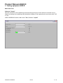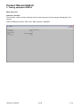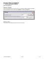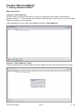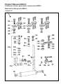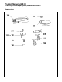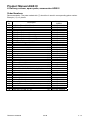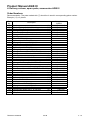
1
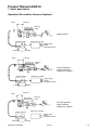
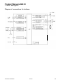
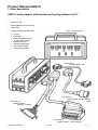
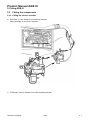
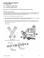
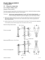
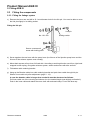
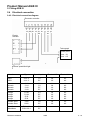
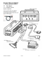
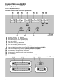
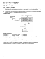
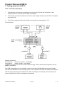
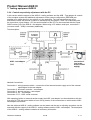
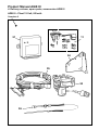
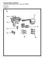
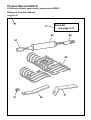
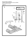
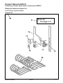
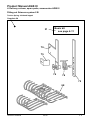
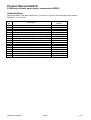
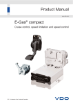
Product Manual
www.vdo.com
AGB III
Automatic Speed limiting
VDO - A trademark of the Continental Corporation
Product Manual AGB III
Overview of Chapter
Topic
Chapter
Short description AGB III
1
Fitting AGB III
2
Testing equipment AGB III
3
Delivery volume, spare parts, accessories AGB III
4
Data Sheets
5
The reproduction, distribution and utilization of this document as well as the communication of its contents to others without
express authorization is prohibited. Offenders will be held liable for the payment of damages. All right reserved in the event
of the grant of a patent, utility model or design.
TU00-0041-0200202
0508
0-2
Product Manual AGB III
Abbreviations
AGB
automatic speed limiting
conn.
connection
DIN
German Industrial Standard
EEPROM
Electrically Erasable Programmable, Read-only Memory
EC
European Community
EMC
Electromagnetic compatibility
EWG
Europäische Wirtschaftsgemeinschaft
Hall
Hall-Effect Sensor
ISO/DIS
International Organization for Standardization/
Designation and Illustration of Symbols
PC
Personal Computer
PWM
pulse with modulated signal
RQ
idling- and end number or rotations control unit (injection pump control unit)
RQV
All-number of rotations control unit (injection pump control unit)
SI
Service Information
StVZO
Straßenverkehrs-Zulassungsordnung (German law for traffic)
TU
Technical dokument
VDA
Association of German Automobile industry
VO
Verordnung (regulations)
TU00-0041-0200202
0508
0-3
Product Manual AGB III
1. Short description
Contents
Short description
2
Volume of operation
2
Advantages
3
Fitting Overview
4
Operation Description Override Element
5
Operation Description Scissors System I
6
Operation Description Scissors System II
7
Diagram of connections for stations
8
AGB II-Testing adapter with interface and testing software for PC
9
Operation
TU00-0041-0200202
10
02-06
1-1
Product Manual AGB III
1. Short description
Short description
AGB III is the third generation of automatic speed limiters. Its construction corresponds to the
European Regulations.
In addition to the top speed limiter which limits the vehicle at pre-programmed value, the unit consists
also of a variable speed limiter (above 30 km/h and the maximum speed limit). The driver can choose
any speed within the above mentioned value and the controller limits the speed according to the
drivers demand. The driver has to press the accelerator pedal for this function. Alternative the unit can
also be pre-programmed for an additional second speed limit below the maximum speed limit.
The electronic control unit is self-diagnosable.
The electrical actuator is a construction part being proved and experienced for many years in manifold
operations of every day's tasks.
Various attaching sets are available for fitting the application parts.
Volume of operation
AGB III limits the maximum speed v-max of vehicles through an electronic control unit of an actuator
working on the diesel pump.
The maximum speed v-max can be regulated at the production of the appliance respectively through
an authorized position, in a range between 2 km/h and 200 km/h.
All inputs and outputs are secured against short cuts.
The appliance can diagnose itself.
The appliance corresponds to the following requirements:
¾ EU guideline 95/54 Electromagnetic compatibility
¾ EU guideline 92/24 Speed limiter
The appliance is equipped with an EEPROM.
The nominal value for the maximum speed is regulated through programming the EEPROM.
TU00-0041-0200202
02-06
1-2
Product Manual AGB III
1. Short description
Advantages
High accuracy:
-
Errors of speed determination < 0.5 km/h or 0.5% relative to C3-signal
-
High control performance
Robust electronic control unit:
-
All in-/outputs shortcut-resistant against mass and U bat
-
EMC-disturbance according to DIN ISO 11452-4 (2000-3) 150 mA
-
Disturbance radiation disturbance grade 3 according to VDE 0879-3
-
Stabile little casing
Ability to self-diagnostics:
-
According to ISO/DIS 9141
-
Error recognition and memorizing
Universal operation possibilities:
-
Programmable electronic controller
-
Various fitting sets
-
Only 2 different plants (12 V, 89 km/h / 24 V, 89 km/h)
TU00-0041-0200202
02-06
1-3
Product Manual AGB III
1. Short description
Fitting Overview
Tachographconnections:
Excess speed /
Fault light
v-imp.
Term. 31
Term. 15
Electronic control unit
Linkage systems
Scissors
system I
Scissors
system II
Electrical actuator
Override cylinder
TU00-0041-0200202
02-06
1-4
Product Manual AGB III
1. Short description
Operation Description Override Element
Injection
pump
Full load
Idling
Idling
Idling position
Full load
Speed signal
Supply
Programmed limit
Electronic controller
Electric actuator
Injection
pump
Full load
Idling
Idling
Full load position
(before reaching
coded max. speed)
Full load
Speed signal
Supply
Programmed limit
Electronic controller
Electric actuator
Injection
pump
Full load
Idling
Idling
Full load position
(after reaching
coded max. speed)
Full load
Speed signal
Supply
Programmed limit
Electronic controller
TU00-0041-0200202
Electric actuator
02-06
1-5
Product Manual AGB III
1. Short description
Operation Description Scissors System I
Full load
Idling
Injection
pump
Idling position
Electronic controller
Electric actuator
Speed signal
Supply
Programmed limit
Idling
Full load
Full load
Idling
Injection
pump
Full load position
(before reaching
coded max. speed)
Electronic controller
Electric actuator
Speed signal
Supply
Programmed limit
Idling
Full load
Full load
Idling
Injection
pump
Full load position
(after reaching
coded max. speed)
Electronic controller
Electric actuator
Speed signal
Supply
Programmed limit
Full load
TU00-0041-0200202
Idling
02-06
1-6
Product Manual AGB III
1. Short description
Operation Description Scissors System II
Full load
Idling
Injection
pump
Idling position
Electronic controller
Electric actuator
Speed signal
Supply
Programmed limit
Idling
Full load
Full load
Idling
Injection
pump
Full load position
(before reaching
coded max. speed)
Electronic controller
Electric actuator
Speed signal
Supply
Programmed limit
Idling
Full load
Leerlauf
Idling
Injection
pump
Full load position
(after reaching
coded max. speed)
Electronic controller
Electric actuator
Speed signal
Supply
Programmed limit
Full load
TU00-0041-0200202
Idling
02-06
1-7
Product Manual AGB III
1. Short description
Diagram of connections for stations
TU00-0041-0200202
02-06
1-8
Product Manual AGB III
1. Short description
AGB II-Testing adapter with interface and testing software for PC
-
Operation test
-
reading/deleting error memory
-
Diagnostics
-
changing adjusted parameter
•
•
•
•
•
•
•
AGB – Testing adapter
v–max
v-variable
distance impulse figure
(at hall effect sensor)
actuator tension
injection pump type
line control On/Off
emergency position
Connection 4
(Testing
Verbindung
4 adapter - PC)
(Prüfadapter - PC)
Connection 3
(Testing
Verbindung
3 adapter - electric actuator
AGB)
(Prüfadapter - elektr. Stellglied
AGB)
Connection 2
(Testing adapter –
Verbindung
2
electronic
controller)
(Prüfadapter –
elektron. Regler)
Connection 1
(Testing adapter – wiring harness)
TU00-0041-0200202
02-06
1-9
Product Manual AGB III
1. Short description
Operation
Components in/at the dashboard and its functions:
1. Excess speed/fault light
The excess speed light is switched on as soon as the programmed max. speed is exceeded by
more than 2 km/h h (e.g. at downward run with regulated injection pump) and is switched off again
by reaching the regulated max. speed. For checking the light, it is being approached by turning on
the ignition and beams for approx. 1 second. In case of an error in the plant the excess speed/fault
light beams permanently.
2. For the operation of variable speed limiter an additional switch is necessary (is not in the scope of
VDO supply).With this switch the any speed can be chosen from the driver between 30 km/h and
the maximum speed limit and will be controlled from the AGB III controller.
TU00-0041-0200202
02-06
1 - 10
Product Manual AGB III
2. Fitting AGB III
Contents
2.1 System Components
2
2.2 Technical Data
3
2.2.1 Electronic Controller
3
2.2.3 Electrical actuator
4
2.3 Fitting the components
5
2.3.1 Fitting the electronic controller
5
2.3.2 Fitting the electric actuator
6
2.3.3 Fitting the linkage system
Fitting the override cylinder
Fitting the scissors system I
The scissors system II (retaining bracket at lever arm)
8
8
10
13
2.3.4 Fitting the excess speed/fault light
16
2.4 Electrical connection
17
2.4.1 Laying the wiring harness
17
2.4.2 Electrical connection diagram
18
2.5 Adjustment of the linkage
19
2.5.1 Adjustment with Scissors System I and Override Element
19
2.5.2 Adjustment with Scissors System II (retaining bracket at lever arm)
21
2.6 After the fitting
23
2.7 Sealing the plant
24
TU00-0041-0200202
0206
2-1
Product Manual AGB III
2. Fitting AGB III
2.1
System Components
a)
b)
c)
d)
Electronical controller
Electric Actuator
Switch for variable v-max limitation (option)
Linkage systems for gas regulation
d1)
Scissors system I
d2)
Scissors system II
d3)
Override element
Wiring harness
e)
TU00-0041-0200202
0206
2-2
Product Manual AGB III
2. Fitting AGB III
2.2
Technical Data
2.2.1 Electronic Controller
Electrical Data:
Polarity reversal protection
according to ISO 16750-2; 28 V, Duration 1 min.
Over voltage protection
400 ms - 60 Volt
Nominal voltage
12 V or 24 V
Operating voltage range 12V
9.5 V to 16 V
Operating voltage range 24V
20 V to 32 V
Tachograph
< 0.5 V level >6.0 V
Hall-effect sensor signal
< 1.5 V level > 6.0 V l
Number of pulses
2400 to 250000 pulses / km
Temperatures:
Operating temperature range
Storage temperature range
– 40°C to + 70°C
– 40°C to + 80°C
Protection Class:
IP 50 DIN 40 050, IP 53 installation position with plug downwards
Casing dimensions:
The dimensions of the casing may if required are found in a special
Customer Drawing.
Programming:
- 89 km
- RQV
- Speed signal control "Off"
- Emergency running position free
- PWM speed signal of the tachograph
TU00-0041-0200202
0206
2-3
Product Manual AGB III
2. Fitting AGB III
2.2
Technical Data
2.2.3 Electrical actuator
Electrical Data:
Nominal voltage range
12 V or 24 V (depending on electrical actuator)
Operating voltage
of electronic controller
Regulation response time
<2s
Insulation resistance
> 500 kΩ
Temperatures:
Operating temperature range
Storage temperature
– 25°C to + 100°C
– 35°C to + 115°C
Protection class:
IP 56 DIN 40 050
Nominal torque:
400 Ncm
Casing dimensions:
The dimensions of the casing may if required are found in a special
Customer Drawing.
TU00-0041-0200202
0206
2-4
Product Manual AGB III
2. Fitting AGB III
2.3
Fitting the components
2.3.1 Fitting the electronic controller
The electronic controller should be mounted in the passenger compartment or cab (if possible close to
the central electrical unit). Mounting in a damp place, e.g. in the engine compartment, may lead to
failures and should therefore be avoided. The plug socket on the control unit must face downwards.
If the controller is to be mounted on its side, the plug socket must face downwards at an angle of > 5°.
Please note protection class:
ECU Installation with connector downwards: IP53
a) Disconnect the battery.
b) Mark where holes are to be drilled (pay attention to air lines etc.).
Use the fitting bracket as a template. The space required for insertion and removal of the plug is
70 mm.
c) Drill 3.9 mm diameter and attach electronic controller.
TU00-0041-0200202
0206
2-5
Product Manual AGB III
2. Fitting AGB III
2.3
Fitting the components
2.3.2 Fitting the electric actuator
a) Attach the actuator retainer to mounting attachments; pre-fit the actuator to bracket and screws
must be tightened in manually-screwed way.
Complete linkage lever arm with link pin and attach it to actuator axle.
b) Select mounting position.
The actuator should be mounted on the supporting frame or on the bodywork. The actuator must
not be mounted on the engine because of the excessive vibration occurring there. Mounting on a
tilt cab is also not usually suitable, as these are sprung and movements may be transferred to the
injection pump via the Bowden cable. The mounting position should be selected so that the
Bowden cable is led to the injection pump by a short route. When laying the Bowden cable, a
minimum radius of curvature of 150 should be maintained. Care should be taken to ensure that the
cable is positioned at an adequate distance from moving parts and is kept away approx. 200 mm
from hot parts as exhaust system, turbo-supercharger or compressor air lines.
c) Remove actuator from bracket and fit mounting attachments as necessary. Attach actuator to
bracket.
d) Offer up actuator and mark drilling positions.
TU00-0041-0200202
0206
2-6
Product Manual AGB III
2. Fitting AGB III
2.3
Fitting the components
2.3.2 Fitting the electric actuator
e) Drill holes 6.1 mm diameter and attaches actuator.
Fitting example of the electric actuator
f)
Fit Bowden cable to actuator into cable retaining bracket.
TU00-0041-0200202
0206
2-7
Product Manual AGB III
2. Fitting AGB III
2.3
Fitting the components
2.3.3 Fitting the linkage system
Moving parts in the linkage system should always be greased prior to fitting.
Fitting the override cylinder
The override cylinder may be fitted only in vehicles equipped with pulling fuel control linkages. Fitting
in a linkage which already includes for example a cut-off cylinder should be avoided (linkage may
break under vibration if too heavy). The maximum override is 50 mm.
a) Remove fuel control linkage and measure its length.
b) Shorten linkage (length of override cylinder = 166.5 mm). Fit override cylinder and set to length as
measured in a) above. If necessary, use the threaded adapters provided.
c) Fit the linkage lever arm on the pump arm and locate the link pin in such a way that it covers a
distance of 30 to 55 mm between idling and full load positions for two-lever pumps (Diameter of
hole for link pin = 10.1 mm).
Fitting link pin
Measurement X (Link pin) 0 30 to 55 mm
Sliding socket
Linkage lever arm
Link pin
TU00-0041-0200202
0206
2-8
Product Manual AGB III
2. Fitting AGB III
2.3
Fitting the components
2.3.3 Fitting the linkage system
d) The outer cable retaining bracket must be mounted on the engine in such a way that the Bowden
cable is on the same level as the link pin. In many cases one of the injection pump bolts may be
used for this. Loose screw and attach holder that it lays at the control unit case and thus becomes
fixed. Tighten screw (Pay attention to the torque)
e) Hang-up the Bowden cable into cable retaining bracket and push inner cable through link pin.
Shorten inner cable only after adjustment (page 3 - 19).
In case the bowden cable is longer than needed it must be shortened as follows:
Pull inner cable out of the covering and shorten it to the needed length (saw slightly and break it).
Push in the inner cable and attach the cover shell with enclosed clamp. Cover with dust cap.
Fitting example Override element
Friction nipple
Shorten bowden cable
Covering
Dust cap
TU00-0041-0200202
Cover shell
0206
2-9
Product Manual AGB III
2. Fitting AGB III
2.3
Fitting the components
2.3.3 Fitting the linkage system
Fitting the scissors system I
The scissors system may be fitted on the injection pump lever arm in vehicles with pulling or pushing
fuel control linkages and Bowden cable fuel control systems.
Tolerances:
Injection pumps regulator adjustment force max. 45 N (must be determined with
running motor). With adjustment force > 45 N to max. 75 N use torsion spring diameter
3.2 mm, according to need left or right hand wrapped (is part of the delivery volume).
a) Measure the distance between the centre of the pump shaft and the centre of the ball stud and
mark off this dimension on the front lever arm of the scissors system. Drill as appropriate and
attach original ball stud.
b) Install the back lever and find out the measurement for the link pin. The link pin should, depending
on the injection pump movement angle, have a movement of 30 to 55 mm.
Determine linkage measurements
dia. 10.1 mm
Fit lever arm upright
shorten lever
Measurement X (Link pin) = 30 to 55 mm
Fit lever arm hanging down
dia. 10.1 mm
TU00-0041-0200202
0206
2 - 10
Product Manual AGB III
2. Fitting AGB III
2.3
Fitting the components
2.3.3 Fitting the linkage system
c) Remove the lever arm and drill a 10.1 mm diameter hole for the link pin. You must be able to move
the link pin slightly in its sliding socket.
Fitting the link pin
Link pin
dia. 10.1 mm
Sliding socket
Secure countersunk
screw with locking paint
d) Screw together the rear lever with the pump lever (the fulcrum of the injection pump lever and the
fulcrum of the scissors system must overlap).
e) Mount back square at front lever full load side. According to working direction use left or right-hand
wrapped torsion spring, fit together scissors system, stretch and secure with disc and bolt.
f)
Fit bowden cable retaining bracket.
g) Hang-up the Bowden cable into cable retaining bracket and push inner cable through link pin.
Shorten inner cable only after adjustment (page 2 - 19).
In case the bowden cable is longer than needed it must be shortened as follows:
Pull inner cable out of the covering and shorten it to the needed length (saw slightly and brake it).
Push in the inner cable and attach the cover shell with enclosed clamp. Cover with dust cap.
TU00-0041-0200202
0206
2 - 11
Product Manual AGB III
2. Fitting AGB III
2.3
Fitting the components
2.3.3 Fitting the linkage system
Fitting example Scissors system I
Friction nipple
Ball stud
gas rod
Split pin
Schenkelfeder
Shorten Bowden cable
Covering
Cover shell
Dust cap
TU00-0041-0200202
0206
2 - 12
Product Manual AGB III
2. Fitting AGB III
2.3
Fitting the components
2.3.3 Fitting the linkage system
The scissors system II (retaining bracket at lever arm)
According to the resp. operation use the fitting set scissors system II A or fitting set scissors system II
B (Chapter 4).
The scissors system II may only be used with injection pumps with fixed idling limit stop, e.g. two-lever
arm or distributor injection pumps with separate stop.
The bowden cable retaining bracket is realized with the outer lever arm.
Tolerances:
Regulator angle of the injection pump 12° to max. 35°.
Injection pumps regulator adjustment force max. 45 N (must be determined with
running motor). With adjustment force > 45 N to max. 75 N use torsion spring dia. 3.2
mm, according to need left or right hand wrapped (is not part of the delivery volume).
a) Measure the distance between the centre of the pump shaft and the centre of the ball stud and
mark off this dimension on the front lever arm of the scissors system. Drill as appropriate and
attach original ball stud.
b) Determine measurement X for the linkage pin with the position of the bowden cable retaining
bracket.
Determine linkage measurements
Position: 1
2
3
Fit lever arm upright
(Figure: Scissors System II B)
dia. 10.1 mm
shorten lever
Measurement X (Link pin):
Position 1 = 52 mm
Position 2 = 43 mm
Position 3 = 32 mm
dia. 10.1 mm
Fit lever arm hanging down
(Figure: Scissors System II B)
TU00-0041-0200202
0206
2 - 13
Product Manual AGB III
2. Fitting AGB III
2.3
Fitting the components
2.3.3 Fitting the linkage system
c) Remove the lever arm and drill a 10.1 mm diameter hole for the link pin. You must be able to move
the link pin slightly in its sliding socket.
Fitting the link pin
Sliding socket
Link pin
dia. 10.1 mm
Secure countersunk
screw with locking
paint
d) Screw together the rear lever arm with the pump lever arm (the fulcrum of the injection pump lever
arm and the fulcrum of the scissors system must overlap).
e) Mount back square at front lever full load side. According to working direction use left or right-hand
wrapped torsion spring, fit together scissors system, stretch and secure with disc and bolt.
f) Hang-up the Bowden cable into cable retaining bracket and push inner cable through link pin.
Shorten inner cable only after adjustment (page 3 - 19).
In case the bowden cable is longer than needed it must be shortened as follows:
Pull inner cable out of the covering and shorten it to the needed length (saw slightly and break it).
Push in the inner cable and attach the cover shell with enclosed clamp. Cover with dust cap.
Assure that the bowden cable has enough free space and does not slide with the engine or the
bodywork in idling position - and full load position.
TU00-0041-0200202
0206
2 - 14
Product Manual AGB III
2. Fitting AGB III
2.3
Fitting the components
2.3.3 Fitting the linkage system
Fitting example Scissors system II (retaining bracket at lever)
Clamp (Bowden cable
retaining bracket)
Ball stud
gas rod
Back
square
Split pin
Torsion spring
Shorten Bowden cable
Covering
Cover shell
Dust cap
TU00-0041-0200202
0206
2 - 15
Product Manual AGB III
2. Fitting AGB III
2.3
Fitting the components
2.3.4 Fitting the excess speed/fault light
The light should be fitted on the dash board in a position which is easily visible to the driver. Cutouts
are already available in some vehicles, and these are blanked off. If there are no cutouts, then fit the
light as follows:
a) Select a suitable position. Note the depth required (60 mm). Mark off the dimensions on the dash
board and cut out as required.
b) Insert light
.
Fitting dimensions for light:
Excess speed and fault light
TU00-0041-0200202
0206
2 - 16
Product Manual AGB III
2. Fitting AGB III
2.4
Electrical connection
2.4.1 Laying the wiring harness
a) Lay the actuator cable from the electric actuator to the electronic controller, fit with cable holders
and secure plugging connection with safety cap. Plug in the plug of the actuator cable according to
connection diagram (page 2 - 18).
b) Lay the cables fixed at the system plug from the electronic controller to the dash board and secure
with cable holders.
c) Lead the cable for the tension supply (rd and br) and speed signal cable (rd - wt) to the tachograph
and shorten it if necessary, remove the safety cap for connection cable to the tachograph. Produce
connection according to connection diagram (page 2 - 18).
d) Lead cable excess speed/fault light (br-bl) and cable tension supply (rd) from tachograph to light,
shorten it if necessary, and produce connection according to connection diagram (page 2 - 18).
Mount safety cap and seal tachograph. Follow the regulations of 05% StVZO for Germany, resp.
the VO (EEC) No. 3821185 for the other European countries.
e) Connect battery.
TU00-0041-0200202
0206
2 - 17
Product Manual AGB III
2. Fitting AGB III
2.4
Electrical connection
2.4.2 Electrical connection diagram
Electronic controller
rd bk br rd
br br
bk
rd ye
wt
Electric
actuator
Tachograph
Speed pulse
Term. –31
Term. +15
Excess speed/fault light
Manufacturer
Type:
Speed impulse
Terminal 15
Terminal 31
414.-.2
414.-.5
C3
B7
A4
A3
A6
A6
Kienzle
Kienzle
Kienzle
Kienzle
1310
1314
1318
1319
C3
C3
B7
B7
A4
A4
A3
A3
A6
A6
A6
A6
Jaeger
Jaeger
Jaeger
Jaeger
G 130
G 134
G 50
G 54
E3
B7
B7
B7
A4
A3
A3
A3
A6
A6
A6
A6
Veeder-Root
Veeder-Root
1426
8300
D3
B7
C4
A3
C6
A6
EGK 100
EGK 100-1
B7
B7
VDO
VDO
MotoMeter
MotoMeter
TU00-0041-0200202
0206
2 - 18
Product Manual AGB III
2. Fitting AGB III
2.5
Adjustment of the linkage
Connect AGB - test adapter between systems plug and electronic controller. Switch on ignition. Engine
of the electrical actuator runs into its idling position (not regulated).
2.5.1 Adjustment with Scissors System I and Override Element
a) Adjust ball stud at actuator lever arm. Transfer the measurement of the regulation range in which
the link pin at the linkage lever arm moves between idling position and full load position to the
actuator lever arm. Fix ball stud.
b) Push injection pump lever against full load limit stop, move the friction nipple onto the link pin and
fix the inner cable of the bowden cable with the setscrew.
c) Push gas pedal or push regulation before the linkage into full load position and hold it. Operate
lever arm full load test at AGB - Test adapter. Injection pump lever arm must be in idling position.
Through regulating the precise adjustment screw of the bowden cable at the electric actuator the
adjustment can be corrected.
Attention:
This adjustment must be made very precisely. In case the injection pump lever arm
does not reach its idling position, over shootings of the coded max. speed of the
vehicle can occur. In case the injection pump lever arm lays at the idling position
and the electric actuator has not yet reached its electrical full load position, it
blocks and through this becomes damaged (braking of the toothed wheels). With
one-lever arm pumps a wrong adjustment above the idling position leads to
switching-off the engine in case gears are changed during fully limited adjustment
position (down-hill driving).This must anyhow be avoided for operations safety
steering support without operation or changing gears without running engine).
TU00-0041-0200202
0206
2 - 19
Product Manual AGB III
2. Fitting AGB III
2.5
Adjustment of the linkage
2.5.1 Adjustment with Scissors System I and Override Element.
Transfer the measurement X, in which the link pin moves between idling position and full load position,
to the actuator lever arm.
LL
VL
LL= Idle speed position
VL= Full load position
Idle speed position
Electric Actuator
LL
VL
VL
LL
VL
LL
VL
LL
LL
Electric Actuator
VL
Full load position (before reaching the coded max. speed)
Electric Actuator
VL
VL
LL
LL
LL
VL
LL
Electric Actuator
VL
Full load position (after reaching the coded max. speed)
Electric Actuator
LL
VL
VL
LL
VL
LL
VL
LL
Electric Actuator
Electric Actuator
Actuator lever
Precise adjustment
TU00-0041-0200202
0206
2 - 20
Product Manual AGB III
2. Fitting AGB III
2.5
Adjustment of the linkage
2.5.2 Adjustment with Scissors System II (retaining bracket at lever arm)
a) Adjust ball stud at actuator lever arm. Transfer the measurement of the regulation range in which
the link pin at the linkage lever arm moves between idling position and full load position to the
actuator lever arm. Fix ball stud.
b) Fix the inner cable of the bowden cable with the setscrew (pump lever arm is in idling position).
c) Push front lever arm of scissors system to full load position and hold it. Operate lever full load test
at AGB – Test adapter. Injection pump lever arm must be in idling position. Through regulating
the precise adjustment screw of the bowden cable at the electric actuator the adjustment can be
corrected.
Attention:
This adjustment must be made very precisely. In case the injection pump lever arm
does not reach its idling position, over shootings of the coded max. speed of the
vehicle can occur. In case the injection pump lever arm lays at the idling position
and the electric actuator has not yet reached its electrical full load position, it
blocks and through this becomes damaged (braking of the toothed wheels).
TU00-0041-0200202
0206
2 - 21
Product Manual AGB III
2. Fitting AGB III
2.5
Adjustment of the linkage
2.5.2 Adjustment with Scissors System II (retaining bracket at lever arm)
Transfer the measurement X, in which the link pin moves between idling position and full load position,
to the actuator lever arm.
LL
VL
LL= Idle speed position
VL= Full load position
Idle-speed position
Electric Actuator
VL
VL
LL
LL
VL
Full load position (before
reaching the coded max.
speed)
VL
Full load position (after
reaching the coded
max. speed)
LL
LL
VL
VL
Electric Actuator
LL
VL
Electric Actuator
VL
LL
VL
LL
Actuator lever arm
Electric Actuator
Precise adjustment
TU00-0041-0200202
0206
Feineinstellung
2 - 22
Product Manual AGB III
2. Fitting AGB III
2.6
After the fitting
Delete all eventually memorized faults by use of the AGB - Test adapter.
Execute a check of the AGB III plant according to the regulation for the execution of test according to
§ 57d StVZO.
Then start a test driving for checking the perfect operation of the AGB III plant and the tachograph.
TU00-0041-0200202
0206
2 - 23
Product Manual AGB III
2. Fitting AGB III
2.7
Sealing the plant
After successful test driving and perfect operation the plant must become sealed according to scheme.
Letter L for paint sealing,
Letter D for wire sealing.
Sealing
Tachograph
red plastic
sealing cap
L
L
L
L
D
L
D
Electronic Controller
L
Linkage
Scissors system I
L
D
D
L
D
Linkage
Scissors system II
L
L
L
L
L
L
D
L
Linkage
Override element
TU00-0041-0200202
L
L
Electric Actuator
L
0206
2 - 24
Product Manual AGB III
3. Testing equipment AGB III
Contents
3.1 Test adapter
2
3.1.1 Complete concept
System components
Operating elements and connection possibilities
2
2
3
3.1.2 Operation description
Plus- and minus pole socket [1, 2]
External frequency input [3]
Lever arm On/Off [4]
Press error memory read / delete [5]
Fault light / excess speed [6]
Lever arm actuation position min/max [7]
Lever arm variable intermediate speed on/S + B [8]
4
4
4
4
5
6
6
6
3.2 Test description
7
3.2.1 Testing in the vehicle
7
3.2.2 Test in the workshop
8
3.2.3 Fault determination, possible reasons, and relief
9
3.2.4 Control respectively adjustment with the PC
3.3 Testing software
11
12
3.3.1 Program code data
System requirements
12
12
3.3.2 Description of program
User surface
Operation
13
13
14
3.3.3 Description of the menu items for AGB III
Main menu File
Main menu View
Main menu Parameter
Main menu Test
Main menu Options
Main menu Extras
Main menu Window
Main menu Help
15
15
15
15
18
21
22
23
23
TU00-0041-0200202
04-06
3-1
Product Manual AGB III
3. Testing equipment AGB III
3.1
Test adapter
3.1.1 Complete concept
AGB – Test adapter
System components
Link 5 (converter USB- serial RS232)
Link between connection 4 and PC.
(For PC without serial com port, not in the
scope of VDO supply).
Connection 4
(Test adapter - PC)
Connection 3
(Test adapter – electric actuator
AGB)
Connection 2
(Test adapter –
electronic controller)
Connection 1
(Test adapter – wiring harness)
TU00-0041-0200202
04-06
3-2
Product Manual AGB III
3. Testing equipment AGB III
3.1.1 Complete concept
Operating elements and connection possibilities
"Front"
[1]
[2]
[3]
[4]
[5]
[6]
[7]
[8]
[9]
[10]
[11]
[12]
[13]
[14]
[15]
}
Plus-pole socket
external
Minus-pole socket
tension supply
External frequency input (speed signal)
Lever arm on/off
Press error memory read/delete
Excess speed / fault light
Lever arm actuator position min/max
Lever arm variable intermediate speed on/S+B
Press variable intermediate speed set/S-B (without Function at AGB III)
Press control gear idling external (without Function at AGB III)
Lever arm gear idling switch-off (without Function at AGB III)
Plug socket for wiring harness connection
Plug socket for electronic unit control connection
PC-Connection
Plug socket for actuator connection (external control AGB)
"Rear"
TU00-0041-0200202
04-06
3-3
Product Manual AGB III
3. Testing equipment AGB III
3.1.2 Operation description
Plus- and minus pole socket [1, 2]
Both sockets [1] and [2] must be supplied by an external power suppy with 12/24 V during a workshop
test.
External frequency input [3]
A speed signal can be connected to this input for the workshop control. This signal can either be
delivered by a tachograph with a pulse-width moduled signal output, a hall effect sensor signal or a
frequency generator.
Signal from tachograph:
Signal from hall effect sensor:
Low level
High level
Inner resistance after low
Inner resistance after high
Specific resistance
Low level
High level
Inner resistance after low
Inner resistance after high
Specific resistance
< 0.5V
> 6.0V
1.8 kΩ ± 50%
2.7 kΩ ± 50%
2.2 nF
< 1.5V
> 6.0V
< 4.0 kΩ
< 4.5 kΩ
< 10 nF.
The device operates with a distance impulse between 2400 Imp/km and 25000 Imp/km.
Signal from frequence generator: Low level
High level
< 0.5V
> 6.0V
The pulse-width moduled signal has for example at 100 Hz a press influence of 20% and an offset of
2V. Thus the vehicle speed can be diversified by frequency adjusting.
Lever arm On/Off [4]
The AGB II - test adapter is being switched on or off with this lever arm. Switching on, the fault light
beams for a moment [6]. During operation the red control diode beams constantly at the lever arm [4].
TU00-0041-0200202
04-06
3-4
Product Manual AGB III
3. Testing equipment AGB III
3.1.2 Operation description
Press error memory read / delete [5]
Error memory read:
After pushing the press for at least 0.5 seconds (during this time the light (6) beams), the error output
starts via the error light (6) in form of a blinking code. The errors are shown as decimal figure with two
decimal positions. The connection between blinking code and respective error shows the blinking code
table.
Blinking code table:
Blinking Error
code
11
fault lamp short to ground
22
speed signal short to ground
24
speed signal fault / line interruption
31
actuator potentiometer fault
33
internal electronic fault
34
road speed pulses implausible
35
configuration data implausible
41
internal wiring short curcuit / actuator wiring short curcuit
42
actuator wiring short to ground
43
actuator motor overload
44
actuator motor wiring interruption
45
actuator lever blocked
The error output is explained in an example and looks as follows:
The blinking code shown above corresponds to the decimal figure 24. From the blinking code table
can be seen that their must be a signal fault. An error is so long shown until through further pushing
the fault press (5) the output of the next fault is required. If there is no more fault the light turns back to
its previous position after releasing the fault press (5). The fault inquiry can only be executed with
standing vehicles!
TU00-0041-0200202
04-06
3-5
Product Manual AGB III
3. Testing equipment AGB III
3.1.2 Operation description
Delete error memory:
For deleting the errors the AGB II - test adapter press (5) must be pushed before and during switching
on and be hold for at least two seconds after switch on. During this period the light (6) is beaming.
Here the speed of the vehicle must be zero! For testing the deleting process the press (5) must be
pushed. Now there should not be shown a blinking code error at the fault light (6). In case the error
memory is not yet empty, the deleting process must be repeated. Actual errors can not be deleted.
Fault light / excess speed [6]
The fault light has various operations. Stored errors can be shown by a blinking code. (See error
memory read/delete). Furthermore an actual fault position of the complete system is signalised
through switching on the fault light. In case the speed regulation Vset is crossed by more than 2 km/h
and the actuator is fully regulated, the excess speed light is being switched on. It extinguishes in case
the speed is below the max. speed regulation Vset +0.25 km/h.
Lever arm actuation position min/max [7]
Operating the lever arm (7) the actuator turns into the fully limited position. This operation is being
signalised through the green control diode at the leverarm (7).
Lever arm variable intermediate speed on/S + B [8]
Operating the lever arm (8) the chosen intermediate speed is the limit and not the max. regulation
speed (see above). During this process the green control diode at the lever arm (8) is beaming.
TU00-0041-0200202
04-06
3-6
Product Manual AGB III
3. Testing equipment AGB III
3.2
Test description
3.2.1 Testing in the vehicle
1.
PulI off the AGB - vehicle plug from the electronic unit control - ignition is switched off - and plug
with connection 1 (test adapter wiring harness) to plug socket (12) at AGB - test adapter.
2.
The electronic unit control must be connected with the plug socket (13) at the AGB - test adapter
with the connection 2 (test adapter electronic unit control)
Test description:
Needed connections:
Connection 1:
wiring harness vehicle
Connection 2:
electronic controller
–
–
test adapter
test adapter
At switched on ignition the AGB - test adapter must be switched on with the lever arm (4). The red
control diode at the lever arm (4) beams, if
a) the connection in the vehicle and to the AGB – test adapter are faultless
b) the tension supply is 12/24V.
The fault light (6) and all control diodes at the AGB - test adapter are beaming by operating the
respective lever arms or presses in the vehicle or directly at the AGB - test adapter
TU00-0041-0200202
04-06
3-7
Product Manual AGB III
3. Testing equipment AGB III
3.2.2 Test in the workshop
1.
The electronic unit control is connected to the plug socket [13] with the connection 2 (test
adapter electronic controller) to the AGB - test adapter.
2.
The actuator is connected with the connection 3 (test adapter actuator) to the AGB - test adapter
plug socket [15].
3.
The tension supply and the speed signal is connected to the input plugs [1, 2, 3].
Test description:
AGB – test adaptor
Needed connections:
Connection 2:
electronic controller – test adapter
Connection 3:
electric actuator – test adapter
In addition the connection from the external tension supply and the external speed signal to the test
adapter is necessary.
The AGB - test adapter is to be switched on with the lever arm [4] with switched on tension supply.
The red control diode at the lever arm [4] beams, if the connections to AGB - test adapter are faultless.
The fault light [6] and all control diodes at the AGB - test adapter are beaming if the according lever
arms or presses at the AGB - test adapter are operated.
TU00-0041-0200202
04-06
3-8
Product Manual AGB III
3. Testing equipment AGB III
3.2.3 Fault determination, possible reasons, and relief
The next page describes a little support in case of an uncorrect operation of the AGB III. In a table
some possible causes and its possibilities of elimination are listed according to the respective blinking
code. With the support of this table the possible cause can be determined and be mended.
The correct process is as follows:
1)
2)
3)
4)
5)
6)
evaluate blinking code
determine error
determine possible reasons in the table
mend error
delete error memory
test correct operation
Blinking code with respective error description
11
22
24
31
33
34
35
41
42
43
44
45
fault lamp short to ground
speed signal short to ground
speed signal fault / line interruption
actuator potentiometer fault
internal electronic fault
road speed pulses implausible
configuration data implausible
internal wiring short curcuit / actuator wiring short curcuit
actuator wiring short to ground
actuator motor overload
actuator motor wiring interruption
actuator lever blocked
TU00-0041-0200202
04-06
3-9
Product Manual AGB III
3. Testing equipment AGB III
3.2.3 Fault determination, possible reasons, and relief
Blinking
code
Possible reasons
Relief
Notes
beam
permanently
a) operation voltage is below 9.5 V.
b) there are one or more actual faults.
a) Test or supply operation
voltage.
b) Read out error and repair
system.
After relief or error,
delete error memory.
This error can only be determined and
read out with the AGB III – test
software as fault light is defect.
Repair fault light.
11
At pushing the START
press, the light must
beam.
22
a) Supply line, short circuit to minus.
b) Tachograph speed impulse output
or additional device at speed
impulse output is defect
a) Repair supply line.
b) Disconnect additional device,
test again. Repair tachograph
or additional device.
This control can be
switched off in the
electronic controller.
24
a) Supply line, short circuit to plus or
interruption.
b) Tachograph speed impulse output
or resp. device at speed impulse
output is defect
a) Repair supply line.
b) Disconnect additional device,
test again. Repair tachograph
or additional device.
This control can be
switched off in the
electronic controller.
31
Short circuit to plus, minus or
interruption of the actuator
potentiometer or supply line. *
Renew actuator or repair supply
line.
Actuator and supply
line must always be
tested.
33
An error occured while reading or
writing to the actuator's EEPROM
Renew electronic controller.
34
Wheel pulse implausible (only with hall
signal). wheel pulse > than allowed.
Check wheel pulse and adjust
according to specification.
35
The electronic controller was initialized
with false data.
Repeat last change.
41
Short circuit, actuator engine or supply
line against plus. *
Renew actuator or repair supply
line.
Actuator and supply
line must always be
tested.
42
Short circuit, actuator engine or supply
line to minus. *
Renew actuator or repair supply
line.
Actuator and supply
line must always be
tested.
43
Short circuit, plus and minus, actuator
engine or supply line. *
Renew actuator or repair supply
line.
Actuator and supply
line must always be
tested.
44
Actuator engine or supply line is
interrupted.
Renew actuator or repair supply
line.
45
Actuator toothed wheel destroyed
through overstressing or defective
adjustment
Correct adjustment of idling and
full load, renew actuator
* In case of short circuits to plus or minus the output driving of the electronic controller are switched off current.
TU00-0041-0200202
04-06
3 - 10
Product Manual AGB III
3. Testing equipment AGB III
3.2.4 Control respectively adjustment with the PC
In this version with the support of the AGB III - testing software and the AGB - Test adapter all controls
of the complete system and additional adjustments of the system configuration (EEPROM) are
possible to be made directly in the vehicle or in the workshop. The test preparations are to be
executed the same way as with a vehicle or workshop test (see page 3-7 and 3-8). Additionally with
the connection 4 (test adapter - PC) the serial interface of the PC is to be connected with the 9-pole
SUB-D socket [14] of the AGB III - test adapter. When using a PC without serial port, connection 5
(converter serial – USB) is necessary additionaly.
Test description:
or
connection 5
(not in the
scope of VDO
supply)
AGB – test adaptor
Needed Connections:
Connection 1: wiring harness vehicle – connection of the external tension supply and of the external
speed dignal to the test adapter.
Connection 2: electronic controller – test adapter
Connection 3: electric actuator – test adapter
Connection 4: PC – test adapter
Connecton 5: PC - USB - serial converter
With operating ignition or external tension supply the AGB - test adapter is to be switched on with the
lever arm [4]. The red control diode at lever arm (4) beams, if the connections to vehicle and to AGB test adapter are faultless
Now the delivered AGB III - testing software can be startet and the test or adjusting operations can be
executed with the support of the AGB III - testing software and the AGB - test adapter. The description
of the AGB III – testing software contains all necessary information.
TU00-0041-0200202
04-06
3 - 11
Product Manual AGB III
3. Testing equipment AGB III
3.3
Testing software
3.3.1 Program code data
Name of program:
Workshop number:
Description of version:
*
AGBDIAG3
D 0000*
1.6.3 *
The description of version will be given by the manufacturer; the workshop number will be given
to the respective country represenation and administerd. The workshop number contains in
addition the country code (here "D" for Germany).
Task:
AGBDIAG3 serves as device for the diagnostics of the electronic controller.
Beside the operation test of the actuator it offers support to further operation tests of the AGB III for
maintenance or installation works.
Furthermore AGBDIAG3 offers the possibility to read and delete the error memory of the electronic
controller. Faults are herewith shown in clear text description.
For the installation and the adjustment of the AGB III to the respective vehicle AGBDIAG3 offers the
possibility to change the most important parameter of the system.
The communication takes place via a diagnostics interface according to IS09141 through the AGB test adapter.
Important!
Before the application is able to read data submitted by the electronic controller, the
communication port has to be set in the Main menu, Options, Submenu Program (see p. 3-21).
The individually given workshop number of the customer is being written in the electronic
controller for all parameter changes and thus allows to control who has made the last change
of a parameter in the connected electronic controller.
System requirements
The following minimum equipment is expected for the operation of the AGBDIAG3:
-
PC with operating system Windows 98 SE, ME, 2000 or XP
650 KB free disc space
min. 128 MB RAM
USB or RS232 port
AGB - Test adapter for the connection of the electronic controller
Microsoft-mouse (or compatible) installed at 2nd serial port
TU00-0041-0200202
04-06
3 - 12
Product Manual AGB III
3. Testing equipment AGB III
3.3.2 Description of program
User surface
AGBDiag3 starts with a welcome screen, showing the name of the program. After few seconds the
main screen appears. The main screen of AGBDiag3 has the Main Menu Bar (1) with Pulldown Menus
(2), the Tool Bar (3) with shortcuts for the submenus and a Status Bar (4). The Version Number and
the Copyright details are shown on the About Screen (5), which can be reached from the Help Menu
(2).
Typical AGBDiag3 Main Window: Main Menu Help, Submenu About.
(1)
(3)
(2)
(5)
(4)
TU00-0041-0200202
04-06
3 - 13
Product Manual AGB III
3. Testing equipment AGB III
3.3.2 Descripton of program
Operation
Call-in of AGBDIAG3:
The Programm AGBDIAG3 starts with double klick on the program name.
Program call-in:
AGBDIAG3.exe
Exit from the welcome screen:
The welcome screen of AGBDIAG3 shuts down automatically after 3 seconds.
Selection from the menu (mouse operated)
Mouse operating
All menues could be opened with the mouse arrow.
Dialogue with the user
The Information, in- and output windows are consiting of predifined posibitities or numerical input
windows. The predifined posibilitie are choosing with the mouse and klick on the parameter.
In the numerical windows the values are changed by direct input with the buttons 0 to 9. Wrong inputs
are displayed in a separate window.
Using of changed values in the controller
Changed values will be used from the controller after sending the data to the ECU and an ignition
reset.
Exit the program
With going to the menue Exit the programm will be closed.
TU00-0041-0200202
04-06
3 - 14
Product Manual AGB III
3. Testing equipment AGB III
3.3.3 Description of the menu items for AGB III
Main menu File
Submenu "Load all Parameters"
Load an existing AGB III parameter file from the PC.
Submenu "Save all Parameters"
Save the AGB III parameter file to the PC.
Submenu "Exit"
Quit the program.
Main menu View
Show or hide Tool- and Status Bar
Main menu Parameter
AGB III AGBDIAG3-screen: Main menu Parameter, Submenu AGB Parameters
TU00-0041-0200202
04-06
3 - 15
Product Manual AGB III
3. Testing equipment AGB III
Main menu Parameter
Changes could be mad with a double klick on the choosed line.
To store the parameter it has to be transmit to ECU and make an ignition reset.
Submenu "Maximum Speed Limit" vset
The max. speed limit vset which shall regulate the electronic controller can directly be entered within
the range from 2 – 200 km/h in steps of 0.1 kmh.
AGB III AGBDIAG3-screen:
Main menu Parameter, Submenu Change "Maximum Speed Limit" vset
Submenu Switchable Speed (Vschalt) (Kl.15 an Pin 5)
Die schaltbare Sondergeschwindigkeitsgrenze (alternativ zur variablen Geschwindigkeitsbegrenzung),
auf die der elektron. Regler abregeln soll, kann hier im Bereich von 2 -200 km/h in Schritten von 0.1
km/h direkt eingegeben werden.
Submenu Wheel Pulse Genarator
Es stehen zwei unterschiedliche Möglichkeiten zur Verfügung:
C3 = PWM Signal vom Tachographen (Wegimpulszahl muss zwischen 2.400 und 25.000 Imp./km
liegen, eine Programmierung der Wegimpulszahl ist jedoch nicht notwendig).
Hall = Hallgeber Signal direkt vom Geber (Wegimpulszahl muss zwischen 2.400 und 250.000 Imp./km
liegen, jedoch muss die Summe von Wegimpulszahl x Maximalgeschwindigkeit < 5.000.000 sein (die
Programmierung der Wegimpulszahl ist notwendig).
TU00-0041-0200202
04-06
3 - 16
Product Manual AGB III
3. Testing equipment AGB III
Main menu Parameter
Submenu "Pulses/km (Hall)" (not with PWM Signal: C3/B7)
Hall sender direkt signal from gearbox sender (the pulses per km must be in range of 2.400 to 250.000
pulses per km). The sum of pulses/km x max. speed must be < 5.000.000.
Submenu "Position Limitation" (Term. 15 to Pin 6)
Here a position limit of the actuator can be preprogrammed (0% no limitation 100% full limitation) in
steps of 1%.
The actuator will be driven to the position as soon as Pin no.6 has a positive signal (12/24V).
Submenu "Actuator Emergency Position"
The emergency position of the actuator can here directly be entered within the range from 0% (no
limitation) - 100% (full limitation) limit in steps of 1%. This actuator emergency position take place of
any fault of the speed signal by using the PWM signal from the tachograph (C3 or B/).
Submenu "PWM Signal Check Interruption" Interruption/ Short to plus and short to ground
The monitoring of the PWM signal from the tachograph can be monitored on to different variants:
*
*
Interruption/ Short to Ubat
Short to ground
The fault recognition activates a position limitation of the activator (see submenu "Actuator Emergency
Position").
Submenu "Type Of Injection Pump"
The injection pump used in the AGB II - system can be adjusted here. At present two different types
can be selected:
*
RQ-injection pump
*
RQV-injection pump
*
SPEC Special Modulator (customer specific value)
By operating this menu the regulation parameter set of the selected injection pump in the electronic
controller is being stored.
Submenu "Speed-Set"
The functionality of the input no. 5 can be fixed with this programming. There are two posibilities:
Variable Speed Limit
Switchable Speed
Submenu "Actuator Working Direction"
The working direction of the actuator is defined.
*
Counter clockwise
This is the default setting for a usual AGB III installation
*
Clockwise
Submenu "Pulses/ Sensor Revolution"
Here there could be choosen the pulses/ sensor revelution. This is necessary to middle the speed
value. The standard programming is 8 pulses/ revelution.
TU00-0041-0200202
04-06
3 - 17
Product Manual AGB III
3. Testing equipment AGB III
Main menu Test
Submenu "Outputs"
The window outputs showing the fault light status and used actuator current.
The vehicle condition has to be a stillstanding vehicle (no speed signal). With the manual operation
mode, the actuator can be driven between 0% and 100% limitation.
AGB III AGBDIAG3-screen: Main menu Test, Submenu "Outputs"
TU00-0041-0200202
04-06
3 - 18
Product Manual AGB III
3. Testing equipment AGB III
Main menu Test
Submenu "Inputs"
Here the connection of the switching inputs and the signal inputs of the electronic controller can be
tested. According to the switching and potential the display of the respective pins are shown with "Off"
or "On".
AGB III AGBDIAG3-screen: Main menu Test, Submenu "Inputs"
TU00-0041-0200202
04-06
3 - 19
Product Manual AGB III
3. Testing equipment AGB III
Main menu Test
Submenu "Version"
The controller version and the workhop number which has done the last change is displayed in this
window.
AGB III AGBDIAG3-screen: Main menu Test, Submenu "Version"
TU00-0041-0200202
04-06
3 - 20
Product Manual AGB III
3. Testing equipment AGB III
Main menu Options
Submenu "Program"
Set of the communication port from the PC (in connection with the AGB III controller).
AGB III AGBDIAG3-screen: Main menu Options, Submenu "Program"
Submenu "Font"
The textfont for the displayed submenus can be selected.
TU00-0041-0200202
04-06
3 - 21
Product Manual AGB III
3. Testing equipment AGB III
Main menu Extras
Submenu "Failure Memory"
All faults which are stored in the AGB III controller are diplayed in this window. Actua faults are
displayed with the "√". The Controller stores also the count the faults (max.15 invents). With the Delete
button the memory could be ereased.
AGB III AGBDIAG3-screen: Main menu Extras, Submenu "Failure Memory"
Submenu "Failure Memory" Delete
The faults within the ECU will be deleting. It will be displayed if there are actual faults in the system.
TU00-0041-0200202
04-06
3 - 22
Product Manual AGB III
3. Testing equipment AGB III
Main menu Window
Here the adjustment of the windows could be fixed.
Main menu Help
Only submenu "About..." can be chosen.
AGB III AGBDIAG3-screen: Main menu Help, Submenu "About..." (Software version information)
TU00-0041-0200202
04-06
3 - 23
Product Manual AGB III
4. Delivery volume, spare parts, accessories AGB III
Contents
AGB III – Plant 24 Volt, 85 km/h
2
AGB III – Plant 12 Volt, 85 km/h
3
Electro kit
4
Fitting set Override element
5
Fitting set Scissors system I
6
Fitting set Scissors system II A
7
Fitting set Scissors system II B
8
Fitting set Scissors system I MB
9
Fitting set Scissors system II MB
10
Basic kit for fitting sets AGB III
11
AGB – Test adapter with interface
12
Accessories
13
Order Numbers
14
Note:
Parts on pages 4-2 to 4-13 are indicated with reference numbers. For designations and
order numbers see pages 4-14 to 4-16.
TU00-0041-0200202
05-08
4-1
Product Manual AGB III
4. Delivery volume, spare parts, accessories AGB III
AGB III – Plant 24 Volt, 85 km/h
Complete 1
11
51
54
55
52
56
TU00-0041-0200202
05-08
4-2
Product Manual AGB III
4. Delivery volume, spare parts, accessories AGB III
AGB III – Plant 12 Volt, 85 km/h
Complete 2
11
51
54
55
53
56
TU00-0041-0200202
05-08
4-3
Product Manual AGB III
4. Delivery volume, spare parts, accessories AGB III
Electro kit
Complete 11
57
62
61
58
63
64
59
TU00-0041-0200202
05-08
60
4-4
Product Manual AGB III
4. Delivery volume, spare parts, accessories AGB III
Fitting set Override element
Complete 21
Basic kit
see page 4-11
31
66
65
67
68
70
TU00-0041-0200202
71
69
05-08
4-5
Product Manual AGB III
4. Delivery volume, spare parts, accessories AGB III
Fitting set Scissors system I
Complete 22
Basic kit
see page 4-11
31
77
73
70
75
74
76
72
71
68
TU00-0041-0200202
05-08
4-6
Product Manual AGB III
4. Delivery volume, spare parts, accessories AGB III
Fitting set Scissors system II A
Torsion Spring: right-hand lapped
Complete 23
31
Basic kit
see page 4-11
78
75
74
77
72
68
TU00-0041-0200202
05-08
4-7
Product Manual AGB III
4. Delivery volume, spare parts, accessories AGB III
Fitting set Scissors system II B
Torsion Spring: left-hand lapped
Complete 24
31
Basic kit
see page 4-11
79
75
74
76
72
68
TU00-0041-0200202
05-08
4-8
Product Manual AGB III
4. Delivery volume, spare parts, accessories AGB III
Fitting set Scissors system I MB
Complete 25
31
Basic kit
see page 4-11
preassembled
TU00-0041-0200202
05-08
4-9
Product Manual AGB III
4. Delivery volume, spare parts, accessories AGB III
Fitting set Scissors system II MB
Torsion Spring: left-hand lapped
Complete 26
31
TU00-0041-0200202
05-08
Basic kit
see page 4-11
4 - 10
Product Manual AGB III
4. Delivery volume, spare parts, accessories AGB III
Basic kit for fitting sets AGB III
Complete 31
91
86
92
93
94
87
88
89
90
97
104
98
99
105
100
96
89
141
95
109
89
107
110
111
110
112
113
108
107
101
102
103
89
93
114
115
116
94
106
93
91
90
90
TU00-0041-0200202
05-08
4 - 11
Product Manual AGB III
4. Delivery volume, spare parts, accessories AGB III
AGB – Test adapter with interface
Complete 41
404
403
402
401
405
TU00-0041-0200202
05-08
4 - 12
Product Manual AGB III
4. Delivery volume, spare parts, accessories AGB III
Accessories
126
TU00-0041-0200202
05-08
4 - 13
Product Manual AGB III
4. Delivery volume, spare parts, accessories AGB III
Order Numbers
Recommendation: The parts marked with (*) should be in stock in corresponding piece number.
Example: (*2) = 2 pieces.
Ref.
No.
1
2
11
21
22
23
24
25
26
31
41
51
52
53
54
55
56
57
58
59
60
61
62
63
64
65
66
67
68
69
70
71
72
73
74
Description
AGB III – Plant 24V, 85 km/h
AGB III - Plant 12 V, 85 km/h
Electro kit
Fitting set Überhubelement
Fitting set Scissors system I
Fitting set Scissors system II A
Fitting set Scissors system II B
Fitting set Scissors system I MB
Fitting set Scissors system II MB
Basic kit for fitting sets AGB II
Test adapter with interface
Electronic controller
Electrical actuator, 24 V
Electrical actuator, 12 V
Holder
Wiring harness
Bowden cable
Fuse clamp
Receptacle
Flat receptacle, isolated, 6.3
Flat receptacle, 6.3
Control lamp, 24 V
Symbol plate v–max
Bulb, 12 V, 1.2 W, DIN 72601, W 5/1.2
Cylinder parker screw, 4.2 x 9.5 DIN 7981
Override element
Reducer, M6 – M8
Reducer, M8 – M6
Cable binder
Holder (Full load)
Clamp nipple
Holder (Outer cable retaining bracket)
Add. Holder
Add. turning lever
Disc, dia. 20 x dia. 8 x 0.5
TU00-0041-0200202
(*1)
(*1)
(*1)
(*1)
(*1)
(*20)
Order No.
AGB III
X10-397-109-132
X10-397-109-131
X39-397-109-027
X39-397-109-048
X39-397-109-049
X39-397-109-050
X39-397-109-051
X39-397-109-084
X39-397-109-075
X39-397-109-062
X12-397-034-001
A2C53091782
408-422-001-014 G
408-221-001-001 P
X11-397-001-033
X39-397-109-030
X39-397-109-047
81 378 001
X11-397-109-004
(*1)
(*2)
X11-397-109-019
X11-397-109-020
(*1)
(*4)
(*4)
X39-397-109-006
X39-397-109-008
X39-397-109-007
(*2)
(*1)
(*1)
(*5)
05-08
X11-397-109-061
X11-397-109-058
X11-397-109-002
X39-397-109-045
X39-397-109-044
X11-397-109-018
4 - 14
Product Manual AGB III
4. Delivery volume, spare parts, accessories AGB III
Order Numbers
Recommendation: The parts marked with (*) should be in stock in corresponding piece number.
Example: (*2) = 2 pieces.
Ref.
No.
75
76
77
78
79
86
87
88
89
90
91
92
93
94
95
96
97
98
99
100
101
102
103
104
105
106
107
108
109
110
111
112
113
114
115
116
117
Description
Back square
(*1)
Torsion Spring dia. 3, left-hand lapped
(*1)
Torsion Spring dia. 3, right-hand lapped
(*1)
Add. Turning lever A
(*1)
Add. Turning lever B
(*1)
Hexagon-Screw, M6 x 30 DIN 933-8.8
Holding square
Disc, A6.4 DIN 9021
Split washer, A6 DIN 127
Hexagon-Screw nut, M6 DIN 934
Cylinder Screw, M4 x 12 DIN 84
Disc, A4,3 DIN 125
Split washer, A4 DIN 127
Hexagon-Screw nut, M4 DIN 934
Hexagon-Screw, M6 x 10 DIN 933-8.8
Hexagon screw with collar, M6 x 30 DIN 933-8.8
Linking pin
(*1)
Disc, dia. 10 x dia. 6.7 x 0.32
(*10)
Socket
(*1)
Conical spring washer, A 10 DIN 137
Hexagon screw nut, flat, M10 DIN 439
Disc, dia. 14 x dia. 5.2 x 1
(*1)
Hexagon screw nut, self-securing, M5
Setscrew, with cone M5 x 6 DIN 915 / ISO 4028
Add. linking pin
(*1)
Clamp
Hexagon screw nut, M8 DIN 934
(*2)
Tooth lock washer, 8.4 DIN 6797
(*1)
Ball stud
(*2)
Disc, A 5.3 DIN 125
Linking lever
(*1)
Split washer, A5 DIN 127
Hexagon screw nut, M5 DIN 934
Cylinder. screw, M4 x 8 DIN 84
Countersunk screw, M6 x 16 DIN 963
(*5)
Split-pin, 2 x 25 DIN 94
Crimp connector
(*20)
TU00-0041-0200202
05-08
Order No.
AGB III
X11-397-109-017
X11-397-109-012
X11-397-109-011
X39-397-109-028
X39-397-109-029
X11-397-109-054
X11-397-109-025
X11-397-109-055
X11-397-109-056
X11-397-109-059
14 016 111
X11-397-109-025
X11-397-109-028
X11-397-109-027
14 016 226-1141
X39-397-106-115
X11-397-109-060
X39-397-109-052
X11-397-001-030
4 079 001-1161
4 095 001-1162
X11-397-109-057
X11-397-001-031
4 003 037
X39-397-106-143
4 - 15
Product Manual AGB III
4. Delivery volume, spare parts, accessories AGB III
Order Numbers
Recommendation: The parts marked with (*) should be in stock in corresponding piece number.
Example: (*2) = 2 pieces.
Ref.
No.
123
124
126
132
133
136
140
145
146
217
218
Plastic seal
Sealing wire, 100 m-roll
Safety varnish
Angle joint, 8
Angle joint, 10
Countersunk screw, M6 x 20 DIN 963
Distance socket, dia. 6 x 5
Torsion Spring dia. 3,2, right-hand lapped
Torsion Spring dia. 3,2, left-hand lapped
Retaining clamp (dia. 7 inside)
Sealing (bowden cable)
401
402
403
404
405
Connecting cable 1 (cable harness)
Connecting cable 2 (electron. controller)
Connecting cable 3 (AGB actuator)
Connecting cable 4 (PC)
Adapter connector (cable harness)
Description
TU00-0041-0200202
(*1)
(*5)
(*5)
(*5)
(*5)
(*4)
(*4)
Order No.
AGB III
81 129 003
X11-000-002-027
X11-000-002-216
X11-397-109-043
X11-397-109-044
X11-397-109-047
X11-397-109-034
X11-397-109-022
X11-397-109-023
X11.397-109-126
X11.397-109-128
X12-397-033-002
X12-397-033-003
X12-397-033-004
X12-397-034-002
X12-397-033-005
05-08
4 - 16
Electric Actuator
Systemkomponente für
AGB II, AGB III
System component for
RSL II, RSL III
Beschreibung:
Das elektrische Stellglied wurde von VDO zur Betätigung des
Einspritzpumpenhebels von Dieselmotoren in Zusammenhang mit elektronischen VDO Reglern konzipiert.
Die elektrische Ansteuerung des permanenterregten Gleichstrommotors erfolgt durch ein pulsweitenmoduliertes Signal.
Aufbau:
Wasserdichtes Alu-Druckgussgehäuse mit PTFE-Membrane
zum Druckausgleich. Dreistufiges Getriebe, das in permanentem Eingriff zur Abtriebsachse steht.
Leitplastikpotentiometer zur Rückmeldung.
Anschlusskabel mit Stecker.
VDO – a Trademark of the Continental Corporation
Elektrisches Stellglied
Description:
Nennspannung:
Nenndrehmoment:
Aufregelzeit:
Isolationswiderstand:
Durchschlagfestigkeit:
Betriebstemperatur:
Schutzart:
Max. Anzugsdrehmoment für
die Antriebsachse:
Max. Anzugsdrehmoment für
die Befestigungsschrauben:
Mechanischer Winkel:
Verstellwinkel:
Anschlussstecker:
(1-2) 1
Technical Data:
12 V
400 Ncm
< 2 Sek.
> 500 KΩ
500 V
– 25°C bis + 100°C
IP56 DIN 40050 Teil 9
10 Nm
12Nm (bei 9mm
Einschraubtiefe)
103° ± 5°
87,5° ± 3°
ITT Canon Sure Seal, 7polig
Rated voltage:
Rated torque:
Up-regulation time:
Insulating resistance:
Dielectric strength:
Operating temperature:
Protection:
Maximum tightening torque
for the output shaft:
Maximum tightening torque
for fastening screws:
Mechanical angle:
Angle of displacement:
Connecting plug:
12 V
400 Ncm
< 2 sec.
> 500 KΩ
500 V
– 25°C to + 100°C
IP56 DIN 40050 part 9
10 Nm
12 Nm (relating to a screw
depth of 9mm)
103° ± 5°
87.5° ± 3°
ITT Canon Sure Seal, 7-pole
TU00-0781-5504620 I 0108 I
Technische Daten:
Technische Änderungen vorbehalten I Technical details subject to change
VDO has designed an electric actuator for actuating the
injection-pump lever of diesel engines to be used with VDO
electronic control systems.
A width modulated (PWM) signal controls the electric motor
(permanently activated direct-current motor).
Design:
Waterproof aluminium diecast housing with a PTFE membrane for pressure compensation. Three-speed gearbox in permanent connection with the output axle.
Conuctive-plastic feedback potentiometer.
Connecting cable with plug.
Elektrisches Stellglied
Electric Actuator
Systemkomponente für
AGB II, AGB III
System component for
RSL II, RSL III
Abmaße (mm):
Dimensions (mm):
Schutzkappe
Protective cap
500
118
5
13,5
M8 x 1
91
104
36
PTFE-Membrane
PTFE-Diaphragm
Anschlussbelegung:
1
Motor (–)
2
Potentiometer (IP–)
3
Potentiometer (IPS)
4
Potentiometer (IP+)
5
Motor (+)
Terminal Connection:
1
Actuator (–)
2
Potentiometer (IP–)
3
Potentiometer (IPS)
4
Potentiometer (IP+)
5
Actuator (+)
Bestell-Nr. / Order No. 408-221-001-001P
Zubehör:
Accessories:
Best.-Nr. / Order No.:
Dämpfungselemente (Teilesatz)
Stellgliedhaltersatz (motorfeste Montage)
Damping components (parts kit)
Actuator bracket kit (engine mounting)
240-110-001-001P
X39-397-112-014
TU00-0781-5504620
Technische Änderungen vorbehalten
0108
Technical details subject to change
(1-2) 2
Electric Actuator
Systemkomponente für
AGB II, AGB III
System component for
RSL II, RSL III
Beschreibung:
Das elektrische Stellglied wurde von VDO zur Betätigung des
Einspritzpumpenhebels von Dieselmotoren in Zusammenhang mit elektronischen VDO Reglern konzipiert.
Die elektrische Ansteuerung des permanenterregten Gleichstrommotors erfolgt durch ein pulsweitenmoduliertes Signal.
Aufbau:
Wasserdichtes Alu-Druckgussgehäuse mit PTFE-Membrane
zum Druckausgleich. Dreistufiges Getriebe, das in permanentem Eingriff zur Abtriebsachse steht.
Leitplastikpotentiometer zur Rückmeldung.
Anschlusskabel mit Stecker.
VDO – a Trademark of the Continental Corporation
Elektrisches Stellglied
Description:
Nennspannung:
Nenndrehmoment:
Aufregelzeit:
Isolationswiderstand:
Durchschlagfestigkeit:
Betriebstemperatur:
Schutzart:
Max. Anzugsdrehmoment für
die Antriebsachse:
Max. Anzugsdrehmoment für
die Befestigungsschrauben:
Mechanischer Winkel:
Verstellwinkel:
Anschlussstecker:
(1-2) 1
Technical Data:
24 V
400 Ncm
< 2 Sek.
> 500 KΩ
500 V
– 25°C bis + 100°C
IP56 DIN 40050 Teil 9
10 Nm
12 Nm (bei 9mm
Einschraubtiefe)
103° ± 5°
87,5° ± 3°
ITT Canon Sure Seal, 7polig
Rated voltage:
Rated torque:
Up-regulation time:
Insulating resistance:
Dielectric strength:
Operating temperature:
Protection:
Maximum tightening torque
for the output shaft:
Maximum tightening torque
for fastening screws:
Mechanical angle:
Angle of displacement:
Connecting plug:
24 V
400 Ncm
< 2 sec.
> 500 KΩ
500 V
– 25°C to + 100°C
IP56 DIN 40050 part 9
10 Nm
12 Nm (relating to a screw
depth of 9mm)
103° ± 5°
87.5° ± 3°
ITT Canon Sure Seal, 7-pole
TU00-0781-5604620 I 0108 I
Technische Daten:
Technische Änderungen vorbehalten I Technical details subject to change
VDO has designed an electric actuator for actuating the
injection-pump lever of diesel engines to be used with VDO
electronic control systems.
A width modulated (PWM) signal controls the electric motor
(permanently activated direct-current motor).
Design:
Waterproof aluminium diecast housing with a PTFE membrane for pressure compensation. Three-speed gearbox in permanent connection with the output axle.
Conuctive-plastic feedback potentiometer.
Connecting cable with plug.
Elektrisches Stellglied
Electric Actuator
Systemkomponente für
AGB II, AGB III
System component for
RSL II, RSL III
Abmaße (mm):
Dimensions (mm):
Schutzkappe
Protective cap
500
118
5
13,5
M8 x 1
91
104
36
PTFE-Membrane
PTFE-Diaphragm
Anschlussbelegung:
1
Motor (–)
2
Potentiometer (IP–)
3
Potentiometer (IPS)
4
Potentiometer (IP+)
5
Motor (+)
Terminal Connection:
1
Actuator (–)
2
Potentiometer (IP–)
3
Potentiometer (IPS)
4
Potentiometer (IP+)
5
Actuator (+)
Bestell-Nr. / Order No. 408-422-001-014P
(Weitere Dokumentation siehe “Technische Kunden-Unterlage” 408-422-001-014P. /
Further documentation see ‘Technical Customer Documentation’ 408-422-001-014P.)
Zubehör:
Accessories:
Best.-Nr. / Order No.:
Dämpfungselemente (Teilesatz)
Stellgliedhaltersatz (motorfeste Montage)
Damping components (parts kit)
Actuator bracket kit (engine mounting)
240-110-001-001P
X39-397-112-014
TU00-0781-5604620
Technische Änderungen vorbehalten
0108
Technical details subject to change
(1-2) 2
Electronic Controller
Systemkomponente für
AGB III
System component for
RSL III
Beschreibung:
Der elektronische Regler wurde für den Einsatz in Bussen
und Lkws konzipiert.
Der Regler verstellt ein elektrisches Stellglied zur Begrenzung der Maximalgeschwindigkeit eines Fahrzeuges. Ein
integrierter Prozessor verarbeitet sämtliche Eingangs- und
Ausgangssignale. Über eine Diagnoseschnittstelle werden
sämtliche Parametrierungen mit einer speziellen Software
(PC) vorgenommen und der Fehlerspreicher bei Bedarf ausgelesen.
Der Regler entspricht folgenden Normen:
EG RL 95/54 EMV in Kfz
EG RL 92/24 Geschwindigkeitsbegrenzer
VDO – a Trademark of the Continental Corporation
Elektronischer Regler
Technische Daten:
Technical Data:
Nennspannung:
Betriebsspannung:
Betriebstemperatur:
Schutzart:
Einbauort:
Einbaulage:
Rated voltage:
Operating voltage:
Operating temperature:
Protection:
Installation place:
Installation position:
12V oder 24V
9,5V bis 32V
– 40°C bis + 70°C
IP53 DIN 40050
Innenraum
elektrischer Anschluss nach
unten (mindestens 5°)
Steckanschluss:
25polig AMP
Programmierung: Grundeinstellung
– Max. Abregelgeschwindigkeit (Vset): 89 km/h
– Var. Zwischengeschwindigkeit (Vvar): 89 km/h
– Wegimpulszahl: C3 Tachograph
– Stellgliedposition Notlauf: 0 %
– Leitungsüberwachung: Aus
– Einspritzpumpentyp: RQV
(1-2) 1
12V or 24V
9.5V to 32V
– 40°C to + 70°C
IP53 DIN 40050
interior
electrical connector facing
downward (at least 5°)
25-pole AMP
Push-on connector:
Program: Default
– Max. cut-off speed (vset): 89 km/h
– Variable speed (vvar): 89 km/h
– Tacho o/p: C3 Tachograph
– Actuator emergency position: 0 %
– Speed signal supervision: Off
– Type of injection pump: RQV
TU00-0782-5704620 I 0108 I
The electronic regulator has been designed for application in
buses and trucks.
The regulator commands an electric actuator to limit the
maximum speed of a vehicle.
An integrated processor controls all input and output signals.
A specific software (PC) linked to an interface allows
parameterization and reading-out of the fault memory.
The regulator complies with the following directives and standards:
EU Directive 95/54 EMC in vehicles
EU Directive 92/24 Road-Speed Limiter
Technische Änderungen vorbehalten I Technical details subject to change
Description:
Elektronischer Regler
Electronic Controller
Systemkomponente für
AGB III
System component for
RSL III
Abmaße (mm):
Dimensions (mm):
14
1
5
2,5
Klemme 15 (UBatt)
Motor –
—
Motorbremse-Schalter
Variable Geschwindigkeit ein
Reduzierung
—
—
—
—
Poti +
Poti Fehlerlampe
Kl. 31 (Masse)
Motor +
Masse Ausgang
—
—
—
—
Geschwindigkeitssignal
—
Diagnose K
Poti-Schleifer
—
13
130
110
65
100
22
129,5
1
2
3
4
5
6
7
8
9
10
11
12
13
14
15
16
17
18
19
20
21
22
23
24
25
25
33
Anschlussbelegung:
Terminal Assignment:
Term. 15, Ignition-battery +
Actuator negative
—
Exhaust brake
Variable speed on
—
—
—
—
—
Potent. pos. contact
Potent. neg. contact
Failure lamp
Term. 31, Ground
Actuator positive
Ground out
—
6
7,5
1
2
3
4
5
6
7
8
9
10
11
12
13
14
15
16
17
Zubehör:
Accessoriers:
18
19
20
21
Gegenstecker
Receptacle shell
22
23
24
25
—
—
—
Speed signal
—
Diagnostic K
Potent. sliding concact
—
Bestell-Nr. / Order No.: A2C53091782
Zubehör:
Gegenstecker:
Accessories:
Steckerleiste, schwarz
Steckerhülse
TU00-0782-5704620
Receptacle shell:
Technische Änderungen vorbehalten
0108
Best.-Nr. / Order No.:
Terminal block cover, black
Female connector
Technical details subject to change
X11-397-109-003
X11-397-109-004
(1-2) 2
Product Manuel AGB III
Change Overview
Date
Chapter-Page
0107
4 - 15
0807
4-14 / 4-17
0907
4-12 / 4-14+16
0408
complete
0508
4-15
TU00-0041-0200202
Comment
X12-397-034-001 was 12-397-034-001
removed: X11-397-109-045, X11-397-109-048, X11-397-007-005, X11-397-109-035,
X11-397-109-036, X11-397-109-037, 81 375 000
removed: wire set KOM (p.12), X39-397-109-035, cable 5-pole 15m, heat shrinking tube
Corporate design changed
with cone M5 x 6 DIN 915 / ISO 4028 was M5 x 5 DIN 913-A2
0508
(1-1) 1