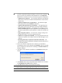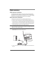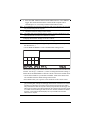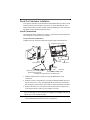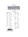
1
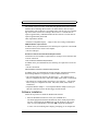
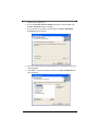
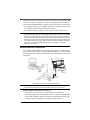
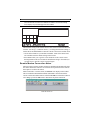
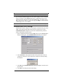
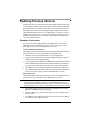
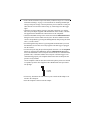
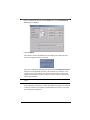
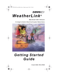
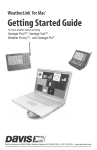
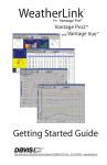
WeatherLink
Vantage Pro®
®
For
and
Vantage Pro2
Getting Started
Guide
TM
FCC Part 15 Class B Registration Warning
This equipment has been tested and found to comply with the limits for a Class B digital device, pursuant to
Part 15 of the FCC Rules. These limits are designed to provide reasonable protection against harmful interference in a residential installation. This equipment generates, uses and can radiate radio frequency energy and,
if not installed and used in accordance with the instructions, may cause harmful interference to radio communications. However, there is no guarantee that interference will not occur in a particular installation. If this equipment does cause harmful interference to radio or television reception, which can be determined by turning the
equipment on and off, the user is encouraged to try to correct the interference by one or more of the following
measures:
•Reorient or relocate the receiving antenna
•Increase the separation between the equipment and receiver
•Connect the equipment into an outlet on a circuit different from that to which the receiver is connected
•Consult the dealer or an experienced radio/TV technician for help.
Changes or modifications not expressly approved in writing by Davis Instruments may void the user’s authority
to operate this equipment.
EC EMC Compliance
This product complies with the essential protection requirements of the EC EMC Directive 89/336/EC
Product Number: 6510SER, 6510USB, 6540,6544, 6550, 6560
Part Number: 7395.210
Rev. B September 2, 2005
WeatherLink® for Vantage Pro® and Vantage Pro2™
Vantage Pro, Vantage Pro 2, WeatherLink, are trademarks of Davis Instruments Corp. Hayes is a registered
trademark of Hayes Microcomputer Products, Inc. Windows is a trademark of Microsoft Corporation.
© 2005 Davis Instruments Corp. All rights reserved.
Information in this document is subject to change without notice.
3465 Diablo Avenue, Hayward, CA 94545-2778 U.S.A.
510-732-9229 • Fax: 510-732-9188
E-mail: [email protected] • www.davisnet.com
Introduction
Welcome to Davis Instruments’ WeatherLink®! The data logger and WeatherLink® software let you connect a Davis Vantage Pro®, Vantage Pro2™ console,
or Weather Envoy™ to your personal computer so you can store, view, plot,
analyze, export, and print weather data collected by the weather station.
Contents of Package
The WeatherLink software is available with two connection types, USB and
Serial. Verify which connection type you have.
WeatherLink With USB Connection
The WeatherLink package with the USB connection contains the following:
• Data Logger with USB Mini connector
• USB - Mini B connector cable to connect the console to your computer.
• WeatherLink Software CD
WeatherLink with Serial Port Connection
The WeatherLink package with the Serial connection contains the following:
• Standard Data Logger.
• 8' (2.4 m) cable with connector to link your console to your computer.
• 9-pin (DB-9) PC COM Port Adapter — Use the 9-pin adapter to connect the
data logger to a 9-pin serial port.
• Loopback connector — The loopback connector is a short piece of cable
with a phone plug at one end and a red plastic cap at the other. The loopback
connector can be used to determine what serial ports are available for the
data logger and for troubleshooting serial communications problems.
• WeatherLink Software CD ROM.
Optional Accessories for Serial Port Connection
The following optional accessories, designed for use with WeatherLink, are
available from your dealer or may be ordered directly from Davis.
• Telephone Modem Adapter — for data transmission from the data logger
using a modem.
• Straight Through 4-Conductor Extension Cable — for more flexibility in the
placement of your console, add one 40' (12 m) extension cable to extend the
distance between your station and the computer. (48' (14.4 m) maximum)
Computer Requirements
WeatherLink software is compatible with computers running various Windows platforms. WeatherLink is compatible with computers using a serial port
connection running the following platforms: 95 (with Internet Explorer 4.0 or
higher), 98, 98 SE, ME, NT 4.0, 2000 or XP.
WeatherLink is compatible with computers using a USB port connection running the following platforms: 98 SE, ME, NT 4.0, 2000 or XP.
1
Note:
WeatherLink is not compatible with the 64-bit version of Windows XP.
The amount of space necessary for the data files depends on the archive interval.
Database files containing data stored at a 30 minute archive interval require
approximately 36K of disk space per month of data. The file size grows depending on the archive interval. For example, data stored at a 1–minute interval
requires approximately 1 MB/month while the data stored at a 2–hour interval
requires approximately 9K/month.
Other requirements include:
• Windows-Compatible Display — High (16-bit) color setting recommended.
USB Hardware requirements
In addition to the provided hardware, the following are required for a local USB
connection between the console and computer.
• One free USB port
Serial Port Connection Hardware Requirements
Listed below are the hardware requirements for creating a local connection and
a remote connection.
Local Connection Hardware Requirements
In addition to the provided hardware, the following are required for a local connection.
• One Free Serial Port
Remote Modem Connection Hardware Requirements
In addition to the provided hardware and the computer equipment listed above,
the following hardware is required for a remote modem connection.
• One external modem to connect to the data logger — The modem must be
Hayes®–compatible and run at 1200, 2400, 4800, 9600, 14400 or 19200 baud.
• One internal or external modem connected to your computer — The modem
must be Hayes®–compatible and run at 1200, 2400, 4800, 9600, 14400 or
19200 baud.
• Telephone Modem Adapter — The Telephone Modem Adapter (#6533) provides the connection between the data logger and the modem.
Software Installation
Follow the steps below to install the WeatherLink software.
1. Place the WeatherLink software CD in your CD ROM drive.
The install program should start automatically. If the install program does
not start, select Run from the Start menu, type D:\SETUP (or the correct
letter for your CD ROM drive), and click OK to begin the installation.
A series of on-screen dialog boxes display, prompting you to complete the
2
WeatherLink configuration.
2. Review the Product Features Summary dialog box and click Next. The
License Agreement dialog box displays.
3. Review the license agreement ant click Next. The Choose Destination
Location dialog box displays.
4. Select the default location to install WeatherLink or find another location by
clicking Browse.
5. Click Next to accept the destination location. The Select Components dialog box displays.
3
The Select Components dialog box displays a selection of the components
that are preselected for installation with WeatherLink. The Components
List check box contains seven items, each with varying levels of importance:
• Application.exe (required) — The executable component of the WeatherLink software. This must be installed with WeatherLink to ensure that the
software runs.
• Application Support Files (recommended) — The additional support
files needed to use real-time Windows menu items.
• Application Documentation (recommended) — The supporting document resources such as the Online Help system and readme information.
• Sample Templates (optional) — The template files available to use/customize your HTML pages. Use this component if you are planning to use
the Internet upload functions and would like to examine the available templates.
• App Config File (required) — The file used to configure settings in the
WeatherLink software. Leave this component checked.
• USB Drivers (required for 6510USB) —The component that installs the
USB drivers required to successfully connect the USB data logger to your
computer.
• Streaming Data Utility (required for 6540, 6544, 6550, 6560) —The
component that installs a program that configures the special parameters of
the Streaming modules.
6. Select or de-select the components list to customize your installation.
If installing the USB version of WeatherLink 6510USB), make sure the USB
Drivers component is selected before continuing. The Install USB Drivers
dialog box displays.
7. Click Yes to verify USB Driver Installation. The Install Driver dialog box
displays.
8. Click Install. All the selected components and the USB drivers are installed.
The Installation Successful dialog box displays.
9. Click OK. WeatherLink has been installed successfully.
Note:
4
If you have a previous version WeatherLink for USB, you may have to uninstall and reinstall the USB driver. See “Updating USB Drivers” on page 16 for more information.
USB Installation
USB Hardware Installation
The WeatherLink USB connection creates a direct local connection between
your computer and your Vantage Pro, Vantage Pro2 console, or Weather Envoy.
Included below are the requirements and instructions for successfully installing
a weather station and related console connection to your computer.
USB Connection Installation
Complete the local USB connection by using the instructions below:
1. Locate the console or Envoy receiving the WeatherLink USB connection.
2. Enter the console’s Setup Mode by pressing and holding DONE, then pressing the down arrow (-). Entering Setup Mode ensures that the station is not
writing any data and saves the current daily weather information to memory.
3. Remove the battery cover from the console back and remove all power by
removing the batteries and AC-power adapter, if present.
Note:
Failure to remove power to the console before installing the data logger may cause damage to the data logger or console. Plugging or unplugging the data logger while power is
applied can lock up or damage the logger.
4. Carefully insert the USB data logger into the large receptacle marked
EXPANSION inside the battery compartment.
Vantage Pro or Pro2 Console
USB-A
Data
Logger
USB Port
Battery Cover
Cable
USB-mini B
5. Locate a free USB port on your computer and connect the USB connector to
the port.
5
6. Insert the USB - Mini B connector on the USB connector of the USB data
logger. The connection between the console and the computer can be
extended up to 16’ (5 m) using a USB-to-USB connector cable.
Note:
Do not attempt to use more than a 16’ extension cable, or the data logger may have difficulty communicating with the computer.
7. Check the baud rate settings on the console.
Note:
The default value for the baud rate setting is 19200. If you have a Weather Envoy, this
value should remain the same in the WeatherLink software.
To display the baud rate settings screen on a console:
Note:
The baud rate settings screen displays only if the data logger has been installed.
• Enter the console Setup Mode by pressing and holding DONE, then pressing
the down arrow (-).
• Use the BAR and DONE to scroll to the Baud Rate settings screen:
The baud rate setting on the console must be same as that set in the WeatherLink
software. Use the up (+) and down (-) arrows to change the baud rate setting, if
needed. Press and hold DONE to return the console to the current weather mode.
• Use the fastest baud rate your modem can handle. 19200 is the fastest baud
rate available and is the default setting on the console.
• Press DONE when you’ve got the correct baud rate on the console screen.
Note:
6
The data logger does not require a constant connection with a computer to continue logging and storing data. Although the data logger should remain connected to the console
at all times, the data logger only needs to be connected to the computer when data is
being downloaded or when the computer is actively using data from the data logger. The
data logger and console can be disconnected from the computer if the console is placed
in a location where the data logger cable cannot reach. However, WeatherLink’s bulletin,
summary, or other real-time window displays are only accessible if the console is
attached to the computer.
Serial Port Hardware Installation
A serial port connection can be installed so that WeatherLink uses a direct, local
connection between the computer and console, or so that WeatherLink uses a
modem connection to a remote weather station. Installation for each connection
type differs, and is explained separately below.
Local Connection
The instructions below explain how to make a typical local connection between
your Vantage Pro console and your computer.
Local Connection Installation
Complete the local serial port connection using the figure and instructions:
Vantage Pro or Pro2 console
COM Ports
(DB-9)
9-pin connector
data logger
battery cover
8' (2.5 m)
data logger
cable
Optional 40' (12 m) 4-Conductor
Extension Cable and Coupler
Connection
Options
Connecting your Computer Directly to your Weather Station
1. Find the weather station console receiving the WeatherLink serial
connection.
2. Enter the console’s Setup Mode by pressing and holding DONE, then pressing the down arrow (-) key. Entering Setup Mode ensures that the station is
not writing any data and saves current daily weather information to memory.
3. Remove the battery cover from the console back and remove all power by
removing the batteries and AC-power adapter, if present.
Note:
Failure to remove power to the console before installing the data logger may cause damage to the data logger or console. Plugging or unplugging the data logger while power is
applied can lock up or damage the logger.
4. Carefully insert the data logger with serial connector into the receptacle
marked EXPANSION inside the battery compartment.
7
5. Guide the data logger cable through the square slot below the receptacle.
6. Restore power to the console by reinstalling the batteries and reattaching the
power adapter, if present. The console beeps three times; each beep occurs
within one second of the others. The Weather Envoy beeps twice.
7. Replace the battery cover, so that the data logger cable exits through the
square slot.
8. Locate a free serial port on the back of the computer and connect the DB-9
pin connector to the port.
9. Insert the cable plug at the end of the short cable coming from the data logger into the receptacle on the end of the 8' cable. Then insert the cable plug
on the end of the 8' cable into the DB9 connector.
The cable connecting the data logger to the computer is 8' (2.4 m) long. Use
a 40' (12 m) straight through 4-conductor extension cable to extend the
connection between the console and computer. Do not attempt to use more
than 40’ of extension cable, or the data logger may have difficulty
communicating with the computer.
Configure the console so that data is transferred between the console data
logger and the computer at the same rate.
10. Check the baud rate settings on the console.
Note:
The default value for the baud rate setting is 19200. If you have a Weather Envoy, this
value should remain the same in the WeatherLink software.
To display the baud rate settings screen on a console:
Note:
The baud rate settings screen displays only if the data logger has been installed.
• Enter the console Setup Mode by pressing and holding DONE, then pressing
the down arrow (-).
• Use the BAR and DONE to scroll to the Baud Rate settings screen:
8
The baud rate setting on the console must be same as that set in the WeatherLink
software. Use the up (+) and down (-) arrows to change the baud rate setting, if
needed. Press and hold DONE to return the console to the current weather mode.
• Use the fastest baud rate your computer can handle. 19200 is the fastest baud
rate available and is the default setting on the console.
• Press DONE when you’ve got the correct baud rate on the console screen.
Note:
The data logger does not require a constant connection with a computer to continue logging and storing data. Although the data logger should remain connected to the console
at all times, the data logger only needs to be connected to the computer when data is
being downloaded or when the computer is actively using data from the data logger. The
data logger and console can be disconnected from the computer if the console is placed
in a location where the data logger cable cannot reach. However, WeatherLink’s bulletin,
summary, or other real-time window displays are only accessible if the console is
attached to the computer.
Remote Modem Installation
Use a remote modem installation to connect your computer to a remote Vantage
Pro or Vantage Pro2 console. A remote modem installation is a connection from
the data logger on the console to a modem that can be dialed and accessed from
a computer.
Vantage Pro or Pro2 console
data logger
battery cover
8' (2.5 m)
data logger
cable
Using Modems to Connect Your Computer and Weather Station
Note:
Before installing the console and modem at a remote location, test the data logger and
connection first using a direct connection like that shown in the section above.
Remote Modem Installation Instructions
1. Install and set up an internal or external modem (according to the
instructions supplied by the manufacturer) for use with your computer. Make
a note of the COM port used by the modem. This information is used when
entering serial port settings for the weather station and console.
9
2. At the station console site, put the external modem in a location where it can
connect to both the logger and a phone jack and plug it into the phone jack.
Note:
Do not turn the modem on at this time.
The cable connecting the data logger to the modem is 8' (2.4 m) long. Use a
40' (12 m) standard 4-conductor extension cable to extend the connection
between the console and modem. Do not attempt to use more than 40’ of
extension cable, or the data logger may have difficulty communicating with
the computer.
3. Plug the external modem into the phone jack.
4. Enter the console’s Setup Mode by pressing and holding DONE, then pressing the down arrow (-). Entering Setup Mode ensures that the station is not
writing any data and saves the current daily weather information to memory.
5. Remove the battery cover from the console back and remove all power by
removing the batteries and AC-power adapter, if present.
Note:
Failure to remove power to the console before installing the data logger may cause damage to the data logger or console.
6. Carefully insert the serial data logger into the receptacle marked
EXPANSION inside the battery compartment.
7. Guide the data logger cable through the square slot below the receptacle.
Note:
Make sure that whenever you connect or disconnect the data logger from the console
that the console is not powered up. Plugging or unplugging the data logger while power is
applied can damage or lock up the data logger.
8. Connect the Telephone Modem Adapter to the external modem.
Note:
Do not use a DB25 (not included) adapter and a gender changer to attach the logger to a
modem because it will not work.
9. Insert the cable plug at the end of the cable into the Telephone Modem
Adapter.
10. Turn the modem ON. Turning the modem on at this point allows it to receive
the modem initialization string from the console.
11. Restore power to the console by reinstalling the batteries and reattaching the
power adapter, if present.
The console beeps three times; each beep occurring within one second of the
others. The Weather Envoy beeps two times, also occurring within one
second of each other. Once power has been returned to the console, the Setup
Mode is automatically displayed.
12. Replace the battery cover, so that the data logger cable exits through the
square slot.
13. Check the baud rate settings on the console. Use the BAR and DONE to
scroll to the Baud Rate settings screen:
10
Note:
The default value for the baud rate setting is 19200. If you have a Weather Envoy, this
value should remain the same in the WeatherLink software. The baud rate settings
screen displays only if the data logger has been installed.
The baud rate setting on the console must be same as that set in the WeatherLink
software. Use the up (+) and down arrows (-) to change the baud rate setting, if
needed. Press and hold DONE to return the console to the current weather mode.
• Use the fastest baud rate your modem can handle. 19200 is the fastest baud
rate available and is the default setting on the console.
• Press DONE when you’ve got the correct baud rate on the console screen.
Pressing DONE in this screen sends the initialization string to the modem, so
you don’t have to turn the console on and off again.
Remote Modem Connection Notes
When accessing a remote modem connection, WeatherLink automatically dials
the station and console whenever an action has been performed in the software
that requires it to talk to the station.
While connected to a remote station, an On-Line icon displays in the toolbar.
This icon indicates that WeatherLink has established a connection with the
remote console and weather station. Select the On-Line icon from the toolbar or
select Hang Up from the File menu to disconnect the phone connection.
Toolbar with On-Line Icon
11
By default, WeatherLink hangs up the connection to the modem after one
minute without any communication with the station. Use the Communications
Port dialog box in the Setup menu of WeatherLink to change this default value.
(See the WeatherLink help files for more information.)
Note:
WeatherLink does not hang up the phone line if the bulletin, summary, or other windows
receiving real-time data from the console are active.
Software Setup
It is easy to setup WeatherLink on your computer once the connection to your
console has been configured. Walkthrough the following to setup and configure
your WeatherLink software and the connection to your console.
Running the Software
To run the software, double-click the WeatherLink icon. If no stations have
been assigned in the program directory, the software prompts you to add a station (see below for details). If there is more than one station in the program
directory when the application opens, the last station that was displayed is automatically opened.
Station Setup
Each station connected to the computer must have its own station within the
software. This tells the software which database to store the new data, provides
the necessary communication settings (serial port, baud rate, etc.), and explains
other station-specific information.
Adding a Station
1. Select New Station from File menu. The New Station dialog box displays.
2. Type the desired station name (up to 40 characters/spaces) into the Station
Name text box. The software uses the first eight characters of the station
name (not counting spaces or punctuation marks) as the name of the directory into which it saves this station’s database and configuration files. The
first eight characters of each station name must, therefore, be unique.
3. Click OK to save the new station or click Cancel to exit without saving.
The software saves the new station, creates a directory and a configuration
file for the station, and prompts you to enter the walk-through procedure.
About the Walkthrough
The software includes a station setup walkthrough that steps you through the
weather station configuration procedures. After adding a new station, the Walkthrough dialog box automatically displays. By selecting Yes, the walkthrough
process begins. By selecting No, the Walkthrough process is exited. You can set
up and configure your station by separately selecting all of the necessary setup
options from the Setup menu. A Walkthrough option is included in the Setup
menu that allows you to access the Walkthrough at any time.
12
Note:
When necessary, the software automatically dials a phone modem station.
By selecting the Walkthrough process, the software displays a series of dialog
boxes. At each step in the Walkthrough process, confirmation boxes are provided to perform or skip the next step in the Walkthrough. To continue, select
OK. To skip this step and move to the next step, select Skip. To cancel the entire
walkthrough process, select Cancel.
Note:
Please refer to the WeatherLink Help for more information about the Walkthrough.
Communication Port Settings
WeatherLink contains a dialog box for locating the communications port (either
USB or serial) that the data logger and console are connected to. Use the
Communications Port dialog box to select the communications port that is
used to communicate with the console.
1. Select Communications Port from the Setup menu or use the Walkthrough to
display the dialog box. The Communications Port dialog box displays.
2. Click Auto Detect. The program searches for the port that the console is
connected to. When the correct connection is found, the following dialog
box displays:
3. Click OK. The Communications Port dialog box displays with the correct
port selected.
4. Click OK to select the port and exit the dialog.
13
Updating Previous Versions
Starting with Version 5.2, WeatherLink has stored additional sensor data in the
weather database. Data files from earlier releases do not contain the additional
data and should be converted first before they are used in the latest version of
the WeatherLink software. The following procedures explain how to convert
older WeatherLink data files for use with WeatherLink 5.2 and later. If you are
updating from version 5.0 or 5.1, there are also instructions on how to retrieve
additional existing data from your Vantage Pro data logger and incorporate it
with your weather data files.
Database Conversion
If you have an existing weather database from WeatherLink 5.1 or earlier
(including versions of WeatherLink 3 and 4), there are two ways to convert
those files for use by versions of WeatherLink 5.2 or later.
Convert a WeatherLink Station
This method converts all the data files in an existing WeatherLink station directory and retains the previously entered station configuration data.
1. Install the new version of WeatherLink in a new program folder.
2. Copy the station folder from the previous WeatherLink program folder to a
WeatherLink 5.2 or later program folder.
3. Use the Open Station command in the File Menu to open the copied station
folder. WeatherLink automatically detects that the station was created by a
previous version of the software and asks to convert the data and station.
4. Click OK to convert the station configuration, including the weather data
files. WeatherLink automatically creates a backup copy of the old files and
then converts them for use by versions of WeatherLink 5.2 or later.
Import Data Files
The Import Database Files menu option allows you to select individual files or
groups of files to be converted for use by WeatherLink 5.2 or later.
Note:
WeatherLink does not import database files created by versions of WeatherLink 5.2 or
later using the Import Database File option. The Import Database Files option only
imports database files created by WeatherLink version 5.1 or earlier. To import data files
from WeatherLink 5.2 to 5.4, copy the .wlk file directly into your weather station directory.
1. Open WeatherLink 5.2 or later and select Import Database Files from the
File menu. The Browse dialog box displays.
2. Select the data files you want to import. Select one file or multiple files in
the same folder.
3. Click Open to convert the selected files. These files are put into a subdirectory called "Converted Database Files".
14
4. Copy the converted files to your station directory.
5. Reopen the station in WeatherLink to view the converted files.
Retrieving Data From the Data Logger
The data loggers for Vantage Pro, Vantage Pro2, and Weather Envoy contain
data and weather variables that were not used by WeatherLink 5.0 or 5.1, such as
UV, solar radiation, rain rate, and ET (Evapotranspiration). Versions of WeatherLink 5.2 or later allow to view and use these variables that earlier versions did
not. Depending on the archive interval used on your data logger, up to 200 days
of this data may be stored on the data logger that you can retrieve and incorporate into a version of WeatherLink 5.2 or later.
To incorporate this data into WeatherLink 5.2 or later data files:
1. Select New Station in the File menu and create a temporary weather station
folder. (See Adding a New Station for more information)
2. Select Download in the File menu or click on the Download icon.WeatherLink does a full download of all data stored in the data logger.
3. Select Browse in the Window menu or click on the Browse icon.
4. Scroll to the beginning of the data file, and write down the time and date of
the first entry in the database.
5. Open the original WeatherLink station using the Open Station option in the
File menu.
6. Select Browse from the Window menu or click on the Browse icon.
7. Select Delete Records in the Browse Menu.
8. Select records for the days following the earliest date in the temporary station database.
Note:
Do not select the records for the day the temporary database begins. Each record can be
deleted individually for that day in the next step.
9. Individually select and delete each record in the data base that is dated after
the earliest record in your temporary database from the Browse Window.
Note:
WeatherLink only downloads data for dates and times not already in the database. Deleting records allows it to download new data.
10. Select Download in the File menu or click on the Download icon to download data from the data logger.
11. Select Delete Station in the File menu and select the temporary station you
created in Step 1 to delete it from the list of stations currently in use.
Recalculate THSW Index
WeatherLink 5.3 and later support a new derived data parameter, the Temperature Humidly Sun Wind (THSW) Index. If your station contains a solar radiation
sensor, this value can be calculated for existing data by selecting the Recalculate
15
THSW Index command in the Browse Menu, which is displayed when the
Browse window is open.
Note:
Be sure to verify that the latitude and longitude settings and daylight savings time settings are correct before using this command.
Updating USB Drivers
WeatherLink 5.6 includes a newer version of the USB drivers that have been
installed for previous versions of the software.
Note:
You must verify the USB driver currently installed on your computer and update the driver
if you have a previous USB version of WeatherLink.
1. Connect the receiver to your computer via the USB data logger.
2. Open the Device Manager on your computer.
3. Select the Universal Serial Bus controller node from the device tree. An
entry “CP2101 USB Composite Device” or “CP2101x USB Composite
Device” should appear at the top of the list. If it does not, disconnect and
reconnect the USB connection.
4. Double click this entry. The Properties dialog box displays.
5. Click the Driver tab. The current driver’s version number and information
displays.
6. If the Driver Date field is 12/16/2004 and the Driver Version field is
4.28.0.2700, the correct version of the USB driver is installed and no update
is needed. If the Data field listed is earlier than this date or if the Driver Version is not the number described, you must uninstall the driver and install the
new version of the USB driver.
7. Click Uninstall to delete the version of the driver.
8. Disconnect the data logger from the computer.
9. Locate and run the PreInstaller.exe file under the WeatherLink directory
(example file directory: C:\WeatherLink\USB_Drivers_4.28x). The new
driver successfully installs itself.
16
Troubleshooting Guide
The following section answers some of the most commonly asked questions
about WeatherLink. Please consult this guide and the on-line help files before
contacting Technical Support.
Contacting Davis Technical Support
Phone Support:
(510) 732-7814 – Monday – Friday, 7:00 a.m. – 5:30 p.m. Pacific Time.
(510) 670-0589 – Technical Support Fax.
E-mail Support:
[email protected] – Technical Support e-mail.
[email protected] – General e-mail.
www.davisnet.com – Davis Instruments’ website. Includes Weather support
information.
Communications Problems
V Why can’t WeatherLink communicate with the data logger and station?
If you are having trouble establishing communication between the weather station and WeatherLink, start by checking the console's own diagnostics. Remove
all power to the console and restart it by restoring power (with the data logger
still attached).
Note:
The data logger uses non-volatile memory, so any previously recorded data is still stored.
However, put the console in Setup Mode (by pressing and holding DONE, then pressing
the down arrow(-)) before removing power, so that no damage to the data logger occurs.
• Three beeps emit from the console, each of which occurs when the weather
station passes one of its diagnostic tests. Each beep follows the previous after
about one second. The first beep notes that the processor is running. The second beep emits when the data logger is detected (if installed) and the third
beeps for the display. If using a Weather Envoy, two beeps emit when it passes
the first two diagnostic tests.
Note:
If you do not hear one or more of these beeps, contact Davis Instruments. Only two
beeps emit if the data logger is not installed.
17
• If the console sends three beeps or the Envoy sends two beeps, See “Communication Port Settings” on page 13 for instructions on checking standard port
settings. If the port settings or the loop back test process identifies a serial port
other than the one selected in station setup, try connecting to the data logger
again.
• Check the serial port adapter if using a serial port connection. Use only the
blue serial port adapter supplied with WeatherLink. Older models, or models
not supplied in the WeatherLink connection kit are not compatible.
• Check the Baud Rate setting on the console and in the Communication Port
dialog box in the software. Make sure they have the same number. Enter the
console’s Setup Mode by pressing and holding DONE, then pressing the down
arrow (-) on the console.
• Scroll through the setup choices by pressing BAR or DONE until you reach
the Baud Rate screen. This screen only appears if the data logger is plugged
into the console.
• Test the serial port using the provided loopback connector. Use the Loopback
button (as opposed to the Test button) in the Communications Port dialog
box to test and find the correct serial port connection and, if a communications
problem exists, it determine whether the serial port or the data logger is not
communicating properly. The loopback function also detects and reports the
presence of any modems.
Use the loopback connector (the short cable with a phone jack on one end and
a red plastic tip on the other) supplied with a Weatherlink serial port connection package.
Loopback
connector
• If necessary, disconnect the cable between your console and the adapter connected to the COM port.
• Insert the loopback connector into the adapter.
18
• Select Communications Port from the Setup menu. The Communications
Port dialog box displays.
• Click Loopback.
The software searches all standard ports and displays the COM port name
where the loopback connector is located.
The correct COM port is automatically selected in the Communications Port
dialog box. If the loopback connector is not found on any COM port, your
serial port may not be working. If a connection does still not exist or if the
loopback test identifies the same serial port you have selected, eliminate the
following possibilities:
Note:
Contact your PC vendor or technical support for more information on these device difficulties.
• Hardware device conflict — Check the Device Manager tab in the Windows
System Properties dialog box to ensure that Windows recognizes the selected
COM port. Consult your computer’s documentation to see how to access the
System Properties dialog box.
19
• The communication port uses a non-standard device name - WeatherLink
recognizes serial ports named COM1 through COM10 only. To use a modem,
specify the underlying COM port on your PC. To find out which port the
modem’s connected to, display Windows’ System Properties > Device Manager > “modem name” Properties > Modem > Port, and check the listed
“modem name” is the modem name you installed.
• Your serial port is defective.
• The loopback connector or the WeatherLink adapter plug is bad.
Program Problems
V The barometer graph on the Bulletin does not “fill in” completely.
When you first load the bulletin, the barometer graph will only fill in completely
when you have data in your database for the last six hours. Make sure of the following:
•
•
•
•
•
There is data in your database for the span of the barometer graph.
The time and date of the stored barometer data is correct in your database.
The time and date on the PC is correct.
The time and date on the weather station are correct.
In the Station Configuration dialog box, set the Download archive data
when Bulletin or Summary is started drop down box to Always or to Confirm each time.
V No wind direction reading (or dashes instead of a reading) appears in my database.
Be aware that if there is no wind speed when the direction is being sampled,
wind direction is not recorded. During intervals with very little wind speed, no
direction may be recorded.
Note:
Since high wind speed is sampled more often, it is possible to have a high wind speed
but no wind speed or direction.
V WeatherLink says “No new data to download” but I know there’s data there. What can I
do?
The Vantage Pro2 system is smart enough to send only data it hasn’t already sent
to the computer. So, when you initiate a new download, the program will
retrieve the first record after the last record shown in the WeatherLink’s Browse
Window. Older data is stored in the logger as a backup. To see how many of
these backup records are stored in the logger, create a new station and download
the data into this new database. Because there are no records stored in the station
you just created, WeatherLink will download everything it has stored.
20
Next, try clearing the archive memory using the clear dialog box. You will lose
any data not already downloaded in your archive memory, but all of your calibration numbers and alarm settings will remain intact. If this doesn’t work,
reboot your weather station (that is, remove, then restore all power to the station).
Note:
Make sure to put the console in Setup Mode (by pressing the DONE and DOWN arrow
keys) before removing the batteries. The ensures the station will remember the current
daily high and low values and the daily rain and ET accumulation.
V When viewing data, dashes appear in place of a value for functions other than wind
direction. Why?
If no data was recorded by a sensor (for example, the sensor was disconnected or
radio interference blocked reception) or if bad data was recorded for a sensor
(for example, the sensor was malfunctioning), the software dashes out the entry
rather than showing invalid data. You can use the record editor to correct these
entries.
V The data I want to see, such as solar radiation, soil moisture, or Temp 2 is missing completely or is greyed-out?
All optional sensors must be enabled in the Station Configuration setup dialog
box before the data will be displayed in WeatherLink. If you are not seeing data
from a sensor that is installed in your weather station, be sure check the Station
Configuration in the Setup Menu and make sure the sensor has been selected.
21
Toolbar Icons
Open
Station
Bulletin
Window
Download
Plot
Window
Strip Chart
Window
Yearly
Rainfall
Database
Window
Alarm
Indication
On-Line
(Hang Up)
This MonthÕs
NOAA Summary
View
Help
Print
Window
Exit
Program
Hot Keys
Main Program Window
Strip Chart Window
Ctrl-A. . . . . . Set Alarms
ESC . . . . . . . Halt redraw
Ctrl-B. . . . . . View Bulletin
Ctrl-M . . . . . Make Default
Ctrl-C. . . . . . Station Configuration
Ctrl-P. . . . . . Print Strip Chart
Ctrl-G. . . . . . Degree-Days Report
F1 . . . . . . . . . Context-Sensitive Help
Ctrl-H. . . . . . Hang Up
F3 . . . . . . . . . Zoom In
Ctrl-I. . . . . . . Communications Port Settings
F4 . . . . . . . . . Zoom Out
Ctrl-J . . . . . . Automatic Download
Ctrl-K. . . . . . Walkthrough
Ctrl-L . . . . . . Download
Ctrl-O. . . . . . Open Station
Ctrl-P . . . . . . Print Active Window
Ctrl-Q. . . . . . Open Plot Window
Ctrl-R. . . . . . Yearly Rain Report
Ctrl-S . . . . . . Open Strip Charts
Ctrl-T . . . . . . Set Time
Ctrl-U. . . . . . Select Units
Plot Window
ESC . . . . . . . Halt redraw
Ctrl-D. . . . . . Choose Date
Ctrl-M . . . . . Make Default
Ctrl-P. . . . . . Print Plot
F1 . . . . . . . . . Context-Sensitive Help
F3 . . . . . . . . . Zoom In
F4 . . . . . . . . . Zoom Out
F9 . . . . . . . . . Overlay Plots
F10. . . . . . . . Last Year Plot
Ctrl-V . . . . . . View Download Log
Ctrl-W . . . . . Browse Database
Ctrl-X . . . . . . Auto Fax Settings
Ctrl-Y . . . . . . View Summary
Ctrl-Z . . . . . . Close Window
F1 . . . . . . . . . Context-Sensitive Help
F2 . . . . . . . . . Sunrise/Sunset Report
F7 . . . . . . . . . NOAA This Month
F8 . . . . . . . . . NOAA This Year
Database Window
Ctrl-D. . . . . . Choose Date
Ctrl-N. . . . . . Add Note
Ctrl-P. . . . . . Print Records
Enter . . . . . . Edit Record
Delete . . . . . Delete Record
F1 . . . . . . . . . Context-Sensitive Help
Yearly Rainfall Window
Enter . . . . . . Edit Year
Delete . . . . . Delete Year
3465 Diablo Avenue, Hayward, CA 94545-2778 U.S.A.
510-732-9229 • Fax: 510-732-9188
E-mail: [email protected] • www.davisnet.com