1
ID -
WELCOME
OF MANTIS
TO THE WORLD
GARDENING!
Here's )'our new MANTIS Tillers.,,
file lightweight wonder that "Makes
Gardening Easier:"
Unlike big tillers, your MANTIS Tiller
weighs only 20 pounds., So it lifts easily;
handles smootht); tills and weeds precisely
And, unlike other small tillers, it features
serpentine tines that churn soil up to ten
inches deep, It creates a soft, smooth seed
bed, even in problem soil,
Once you know how to use your tiller
cmTectl}_ we guaTantee you'll love it So
first, please read this manual, It shows, step
by step, how to use your tiller safel}: Plus,
it shows how the MANTIS Border Edger
can make light work of your edging needs_
tf you have questions about any topic in
this Manual, or if you wish to order
MANTIS Attachments, contact ),our local
authorized MMq'IIS dealer.
TABLE OF CONTENTS
Safety Rules & Warnings ....................
Safety Decals .......................................
Engine & Fuel Warnings ......................
Assembly and Mixing Fuel ........................
Starting .....................................
Additional information
................................
What to Do Just in Case ..........................
Getting to -Your Garden ..........................
Tilling & Cultivating
....................
Iine Positioning ...........................
Cultivating ...................................
2
3-4
3
4
5-7
7-8
8
8
9
9-10
10
i0
Maintenance
...........................
t 1-12
Storage ................................................
13
Trouble Shooting & Specifications .......... I4-I5
Sen.ice Maintenance Guide .................
I5
Using The Border!Edger Attachment .........
16
MANTIS Tiller L'_sembly Layout ..............
17
Engine Parts Assemblies .......................
!7-18
EPA Phase 2/California Tier III Emission
Control Warranty Statement .................
19
Limited Warranty Information
................
20
SAFETY
RULES
& "WARNINGS
You will notice throughout this Owners Manual Safety Rules and Important
understand and obey these warnings for },our own protection,
I. Special
Notes,
Make sure you
Safety Information
,t,,,,,,,,,,i,,,,,,,,,,,,,i,,t,
,,,,,,,,,,
,,,,
A WARNING
AWARNING _ DANGERA
:::ATTENTION:
....
:::
THIS SYMBOL
: TO REDUCE
POINTS
: OUT OUR IMPORTANT
S AFETYINSTRUCTIONS.
.....
:
:
IW.EN
YOU
SEETHiS
SYMSOL,
A
IHEED
IT'S
WARNING!!
THE POTENTIAL
A
FOR ACCIDENTS,
COMPLY WITH THE SAFETY INSTRUCTIONS
: : fIN
THISMANUAI-
FAILURE
TO COMPLY
PERSONAL
STAYALERT!!
....:
II. Safety
* DANGER
MAY RESULT IN SERIOUS
INJURY, AND/OR
: AND PROPERTY
: :
:
EQUIPMENT
DAMAGE.:
:
....
& Warnings
_, WARNING
IMPROPER
,, DANGER
A
USE OR CARE OF THIS TILLER OR FAILURE
PROTECTION
CAN RESULT
IN SERIOUS
TO WEAR PROPER
_, WARNING
INJURY.
The Engine
product
READ AND UNDERSTAND THE RULES FOR SAFE OPERATION
AND ALL INSTRUCTIONS IN THIS MANUAL.
Exhaust
contains
from this
chemicals
to the State of California
cancer,
WEAR HEARING AND EYE PROTECTION.
birth defects
reproductive
known
to cause
or other
harm,
PRODUCT EMISSION DURABILITY
The 300 hour emission durability compliance period is the time span selected by the manufacturer certifying die
engine emissions output meets applicable emissions regulations, provided that approved maintenance procedures are
followed as listed in the Maintenance Section of this manual
III. Safety
Decal
Information
become
.4° important pan of the sa[ety sysLem incorporated
in this t_|]er are the warning
and information decats fotmd on various parts of the tiller These decals must be replaced
in time due m abrasion, elc It is vottr responsibility to replace these decals when they
hard to read The location and part nu_nbers (P/N) of these decals are illustrated on Page _[7
CUTi;{_GHAZARD; KEEP
FEET AND HANDS AWAY
FROM ROTATING TINES.
DO NOT CARRY THE
TILLER IN THIS
POSITION
READ OWNER'S r,V_NUA[
BEFORE USI._GTILLER,OR
PERFORMII_G ANY REPAIR
OR MNt_TENN_CE KEEP
OON'I FUEL,REFUEL,
OR CHECK FUEL WHILE
SMOKINB, OR NEAR Ar|
OPEN P'LAMEOR
S/_E
PLACE
OWNERS
V_ANUAt IN A
SOURCE
OTHER IGNITIO}_"
50:1
_
PtN 4043
CALr_tO[_: WHEN ASSEMBUt_R
EMBSION
CONTROL
IMPORTANT
EMt$SIO_
ENGIP_E INFORMATION
¢r3MPUAS'CE
PER)CO:
"_
300 HOURS
-
AD3USTMENTS
[_
...........
FAMILY
: 4EHX_,_214R_
is EM
(Er=Oin_Modification}.
f3nOil_E
THiS ENGINE
MEriTS U3, EPA PH2 AND 2035
2005 CALIFORI_IA
EMISSION
REGULATIONS
FOR SOR£s, REFER
TO OWNER'S
i'aANUAL
FOR t_AINTENANCE
SPECIFICATIONS
AF'_D
ENGII;E
ThE _mlsst_)nc0nt_'01
tHE HAt,IDLES,MAKE SURE
FUELTANK FACES OPERATOR.
THIS ISTHE BEAR OF THE
TILLER, REFERTO ASSEMBLY
INSTRUCTION ON PAGE 7
II_CORRECTASSEMBLY
--WEA,_ EAR A_D EYE
PROTECTIOFJ
MIX UNLEADED GAS
WITH 2 CYCLE 50:1 OIL
_[_tOJO_I}_O]J-B_!
Ioc_tedonEngin_
D_SPLA{_EI,tE_tT
_
: 2t-2c€1
_
_:/3tBm
{0_r
this
intormation
EXAMPLE
Oor,label
NLY,
wries b),FAMILY)
]IF DtE TILLER IS USEDIMPROPERLY OR SAFETY PREOAUTIONS ARE NOT FO_OWED, [I
[ : THE USERS RISK SERIOUS INJURY'tO THEMSELVESANDOTHERS, READAND :: [I
1:iu_o_nsra,vo
r,,s Ma_ua,
_E_OnE
arrEMen,vc
roOP_RAr_
rn,ST,LLER:
: i II
3
IV. Warnings
- Do's
Read and understand
the owner's
manual
Pay particular attention to all
sections regarding safety
I. Ahvays keep a firm grip on both
handles while the tines are mm,ing and/or
die engine is running BE AWARE!! The
tines may coast after throtde trigger is
released Make sure tines have come to a
complete stop and engine is off before
letting go of the tiller
2. Always maintain a firm footing and
good balance Do not overreach while
operating the tiller. Before you start to use
the liller check the work area for obstacles
that might cause you to lose your footing,
balance or control of the rrmchine
3, Thoroughly inspect the area where
equipment is to be used and remove all
objects, which can be thrmwt by the
machine
4 Al'_ays keep area clear of children,
pets, and bystanders
5. Always stay alert. \.Vatch what you
V. Warnings
- Don'ts
Don't use tiller with one hand Keep
both hands on handles with Fingers and
thumbs encircling the handles, while tines
are moving, and engine is running
Don't overreach
all times
Keep a good footing at
VI. Engine/Fuel
Warnings
Always use fresh g,'tsotine in the fuel
mixture. Stale gm_oline can cause damage
Always store fuel in containers
specifically designed for this purpose.
Always pull starter cord slowly until
resistance is felt Then putl cord rapidly to
avoid kickback and prevent arm or hand
injun'_
VII. Engine/Fuel
"Warnings-
are doing and use common sense Do not
operate unit when fatigued
m be sure the equipment
condition
6. Always dress proper!>: Do not wear
loose clothing or jewelD; they might get
caught in moving parts. Use sturdy gloves
Gloves reduce the uansmission of vibration
to your hands Prolonged exposure to
vibration can cause numbness and other
ailments
12, Use extreme caution when reversing
or pulling the machine towards you
7,_xaqtile working, al,vays wear
substantial footwear and long trousers. Do
not operate the equipment when barefoot
or wearing open sandals
8_ Always wear ear and cye protection
Eye protection must meet ANSI Z 87 I. !to
avoid hearing damage, we recommend
hearing protection be worn whenever using
the equipment
is in safe working
13. _'brk only in daylight or good
artificial light
I4_ Always be sure of your footing on
slopes
15. Exercise extreme caution when
changing direction on slopes
i6, Mways keep a safe distance
between two or more people when
_.orking together
17 Always inspect your unit before
each use and ensure that all handles,
guards and fasteners are secure, operating,
and in place
9. To reduce fire hazard, kcep the
engine, and petrol!gas storage area free of
vegetative material and excessive grease
18_ Always maintain and examine your
filler with care. Follow maintenance
instructions gh, en in manual
10. Start the engine carefull); according
to d_e manufacturer's instructions and x_,ith
feet well away from tool(s)
19_ Always store tiller in a shehcred
area (a dragplace), not accessible to
children. The tiller as *veil as fuel shotdd
not be stored in a house
I 1+Keep all nuts, bobs -<tlidst'tews tight
Don't run with the machine, walk
Don't work on excessivelysteep slopes
Don't attempt to clear tines while they,
are moving. Never try to remove jammed
materia! before s_vitchingthe engine off
and making sure the tines have stopped
completd):
Don't allow children or incapable
people to operate this tiller
Don't operate while under
the influence or alcohol or drugs
Don't attempt to repair this tiller Have
repairs made by a qualified dealer or
repainnan_ See that only original MANTIS
parts are used
- Do's
Ahvays operate engine with spark
arrestor installed and operating properly
The use of spark arrestor mufflers is
required by law in the stare of California
(Section -b_2 of the California Public
Resources Code), as well as in other states
or municipalities Federal laws apply on
federal lands
Stop the engine whenever you leave the
machine
Allow the engine to cool before storing
in any enclosure
If the fuel tank needs to be drained, this
should be done outdoors.
Don'ts
Don't fuel, refuel or check fuel while
smoldng, or near an open flame or other
ignition source Stop engine and be sure it is
cool before refueling.
causes spark outside the cylinder During
periodical checks of the spark plug, keep
plug a safe distance from cylinder to avoid
[_urning of evaporated fuel h'om wlinder
Don't leave the engine running while the
tiller is unattended. Stop engine before
putting the tiller down or while transporting
from one place to another
Don't check for spark with spark plug or
plug \*_reremoved. Use an approved tester.
Don't operate your tiller if daere is an
accumulation of debris around the muffler,
and cooling fins
Don't crank engine with spark plug
removed unless spark plug wire is
disconnected, SparM can ignite fumes
Don't touch hot mufflers, cylinders
or cooling fins as contact may cattse
serious burns
Dml_t run engine v,hen the odor of gasoline
is present or other ex'ptosive conditions _'dst
Don't change the engine governor
setmag or over speed the engine..
Don't refuel, start or ran this tiller
indoors or in an improperly ventilated area
Don't run engine when electrical sTstem
4
Don't operate the unit if gasoline is
spilled Clean up spill completely before
starting engine
ASSEMBLY
,
,
,
,
,
,
,
,
WARNING• OANG R
IMPROPER ASSEMBLY OF THIS 77LLERCAN RESULT IN SERIOUS
iNJURY. MAKE SURE TO FOLLOW ALL INSTRUCTIONS
CAREFULLY.
IF YOUHAVEANY QUESTIONS,CONTACTYOURLOCAL
AUTHORIZEDMANTISDEALER
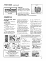
"_%urMANTIS Tiller comes partially assembled You must
install only the handlebars, the carrying handle, and the tines
This will take just a few minutes if you follow the directions
40
First, take all items out o[7the carton. But do not remove
the cardboard from around file Iiller_ base,
Quantity
1
1
2
1
1
The list at the right, shmvs the parts that come with your
tiller Check to make sure you have them
The bag of hardware is in the plastic bag containing
O_mer's Manual and Video
the
To assemble your MANTIS Tiller, you'll need two 7/I.6"
wrenches or two adjustable w'renches We sugges! that you
install all nuts and bolts only "finger tight" _ that is, onehalf to one full turn _ until you've completed assembt):
The nuts are self' loeldng, but you must use a wrench to
tighten them completely°
HOW
IO
ASSEMBLE
LOWER
1
1
1
2
4
2
2
2
1
2
2
HANDLES
T0 identify part numbers, see pages 6 and 27
I,, Use the protective cardboard slem-e to stabilize
your tiller, Stand the engine assembly (#8) up.
2 Lay the handle parts within em_yreach You'll need
one of the handle clamps (#-38) and one of the lower
handles (#3) Note that the lower handles have a short leg
on one end (Picture 1)
Description
*Key #
Upper Handle ,-Lssembty
2
Uppcr Handle Throttle Side Assembly
i
I_ower Handles
3
Pair Ti[lerfCultivator Tines
26/27
Engine Assembly (includes Fender
Guard & Worm Gear Ti_nsmission)
8, 7, 42
Handle Brace
5
Plastic CarrTing Handle
29
Bag of Hardware Containing:
Cap Screws
34*
Lock Nuts
35
Bolts (3" long)
36
Tine 'Retaining Pins
28
Handle Clamps
38
throttle Clips
6
Bolts
39
Knobs
40
_Th_e tmmburs a_c th_ same mmlbct_ shown tm lhe Par!s l.aLvouton
page t 6.
3 Fit the handle clamp along the OULsideof the short
leg Line up the hotes on the clamp and the teg.
4 Choose one of the two 3-inch bolts (_36) Slide it
through the first set of holes _ near the elbow where the
lower handle curves (Picture 2)
i
,#,_!i:i;:::i
.:!l!:i:i,:_
5 Now slide the odaer lowm handle onto the 3-inch
bolt. (Picture 3) Fit the other clamp onto this other
handle's short leg Add a nut and tighten finger tight
6 Locate the worm gear housing. It starts just above
and extends dmvn through -- the tiller's red fender guard
You'll notice that there's a recessed channel on either side
of the housings top. (Picture 4 )
Picture
t
Picture
2
Picture
3
NOTE:
7 Take the lower handles that you've just put together.
Slide them into the two recessed channels.
THE
LOCK NUTS
_!t },,lakesure you insert them from the rear of the tiller
(gasoline tank faces the opetator)_, so that the bolt fits
along the back of the housing. (Picture 5)
ARE STAMPED
8 Slide the second 3-inch bolt through the second set of
holes in the short legs.. Add a nut and tighten finger tight
112TO 1-112
TURNS
FINGER
TIGHT
IS
APPROXIMATELY
J
Picture
4
Pictt_re
5
IIIJ/ll
I/
I
/Jill
I
/
ASSEMBLY
(continued)
_-..z,,,
{4;÷2._:
HOW TO ASSEMBLE
UPPER HANDLES
&
PLASTIC
visually check that the throttle triangle
hits both the idle screw and the rut!
open stop. THIS MUST BE DONE
BEFORE STARTING 'I'HE ENGINE
CARI/_YING
1 Lightly squeeze the lower' handles
(#3) toward one another so that they
line up with the two smaller holes on
rite carding handle (#29). Ihen slide
the carrying handle over and down rite
lower handles It will rest about four to
six inches
above tile engine.
(Picture
2 Gently pull the lower handles
to their original position
1)
out
3 Attach the upper handle assembly
(#1) - the handle with the throttle
cable and ground wire - onto the fight
handle, and secure with the handle
knob (#40) and t round head bolt
(#39) (Picture 2) Be sure you have
proper throttle movements
and that
the throttle cable is not wrapped
or
twisted around the handle bar°
Squeeze trigger and let go, The triangle
must click in both directions
tf there
is any doubt, remove air filter and
4 Follow the same steps to install
the left upper handle onto the other
lower handle (Picture 3)
Picture
I
Picture
2
Picture
3
Piclure
q
5 Use the clip (#6) to secure the
throttle cable and wire in place on the
lower handle (Picture 4)
6 Now install the Handle Brace.
Line it up with the holes on the upper
handles. Then insert a Cap Screw
(#34) and a Lock Nut (#35) on either'
side (Picture 5)
7 Use a wrench to tighten
Screws and Lock Nuts
Cap
A
8 Now use wrench to tighten all
nuts and bolts firmly and securely.
IMPORIANI
WARNING:
NOIE:
Improper throttle
instaIlation can
cause tines to
Make sure you have installed the
handles properly. When you stand
behind your tiller, holding the
handles, you should face the
gasoline tank
rotate unexpectedly
Picture
Assembling
the "Tines
fbr
Tilling
1 Remove the cardboard
),our filler's base
from around
2 Slide the tines onto the axle shafts
The "D" hole goes on the outside
3 Make sure you've installed the tines
properly for tilling.. Liken the tines to
),our fingers_ When your palm faces the
ground, }'our' fingers cur! dog,m. Stand
behind the Tiller and hold your hand
next. to the tines,. Do the tine blades curl
down, ,as your fingers do? If so, they are
in the tilling position (To sa_qtch to the
cultivating position, see page 10)
4 To secure each line to the axle,
insert a fine retaining pin_
IMPORIANI
NOIE:
Before you use your blANI'tS "[flier,
read the Safety Rules & Warnings
on
pages 3-4_
6
5
Your MANTIS Tiller comes with a
free pre-measurcd
bottle of two-cycle
engine oil Here's how to mix the oil
with the gas:
proper
1 Pour !/2 of the g_oline into a safe
container, Do not rob: the fuel and oil in
the engine fuel tank
Remember
Z Add 2 6 ounces of two-cycle
engine oil to the gasoline and mix
Then add the rest of the gasoline
3. Screw the cap onto the gasoline
can. Then swirl the can to blend the
oil and gas.
4 CarefuIly pour the fuel mix into
the tiller'_ fuel tank After putting the
fuel tank's cap back on, wipe up any
spilled fuel from tank and gasoline
can..
IMPORTANr:
"l_vo stroke fuel sepmates and ages Do
not mix more than you will use in a
monflt. Using old fuel can cause
difficult starting or engine damage
Shake fuel container to thoroughly mix
fuel before each use Do not attempt to
run your engine on gasoline onl); use
fuel mixture
Need more pre-measured
engine oil?
You can order it from ),our local
authorized
MANTIS dealer
_....
*Always mix two-cycle oil with
gasoline before fueling your filler,
Never, ever run your tiller on gasoline
alone This will ruin your engine and
void all warranfies.
• Alw;lys use a clean gas can and always
use unleaded gas,
• Never u3 to mix the oil and gasoline
in the engine tklel tank
• Always mix oil and gas in the proper
proportions:
2 6 ounces of two-cycle
engine oi! to one gallon of unleaded
gasoline.
IMPORLa2qI"
NOIE:
Do Not use old or stale oil/gasoline
mixture. Ahvays use the proper
oil/gasoline
mixture,
l[ you do not,
your engine will suffer rapid,
permanent
damage. And you will
void the eu#ne warrant):.
ASSEMBLY
(comi..ed)
1V'dxingFuel
•,1%:i!•:_i:/_!
::::-%•: _k
': ..... i :•:,,•• ••
Your MANTIS Tiller is powered by a
commercial two stroke, air cooled engine
which requires a fuel mixture of gasoline
and lubricating oil.
WARmNG° DANGHR
FUEL IS EXTREMELY FLAMMABLE.
HANDLE IT WITH CARE. KEEP AWAY
FROM IGNITION SOURCES. DO NOT
SMOKE WHILE FUELING YOUR :
Use a mixture of 50 parts unleaded
regular gasoline and 1 pan two-stroke
MANTIS oil (50:1) Use branded 89 octane
MANTIS :::50:i
(R+M+2) unleaded gasoline or gasohol
(maximum I0% ethyl alcohol, or 15% MTBE, no methyl alcohol )
STARTING
To Start Your Tiller for the
First
Time:
1 Fill the fuel tank with the proper
oil/gasoline mixture
(See previous section )
2 Hand tighten
until it's snug
the gasoline
3 Place the oi! switch
"start/on"
position
cap just
into the t
(Picture
1)
4 Pull the choice button all the way
out, to completely close the choke•
(Picture 2)
5 Locate the purge bulb on the
upper right of the engine, in front of
the fuel tank (See Picture 3) It sends
fuel into the carburetor, for easy
starling.
Press the purge bulb until
you see fuel flow through the clear fuel
return line Since you're starting
';eold," yon may need lo press six to
eight times As soon as fuel starts
flowing through the clear fue! line, stop
pressing! (Picture 3)
five times. Overpulling may cause
flooding Also, bear' in mind that, when
the engine fires, it only coughs or
sputters,
and will not run on choke.
6. Don't press the throttle trigger
during the starting of the engine.
9 Then putt the st,alter cord again
The engine should st,art and ran,. Let the
engine warm up two to three minutes
before using
7. Pull the starter cord (Picture 4)
until resistance is felt Then give the
recoil starter cord a few brisk pulls until
the engine fires. Note: Pull the starter
cord about t2" to 18". During cold starting, you may need to pull at least three or
four' times before the engine fires,
NOTE: When the choke is closed,
never pull the cord more than four or
8 Push the choke button in, all the
wa), to open the choke (Picture 5)
Follow these steps whenever you are
starting the engine "cold", or whol the
engine has run dry and you have jvst
added fi_d RemembeT; ahvays use short,
brisk lmlts Don't give the cord a long,
forceful yanh_ And, do not let the cord
snap back fllto the starter hm_sing,
Never use starting fluids as the)' will cause permanent
engine
damage° Using them will void the warranty
Before you use the
tiller, read the Safety & Warning rules on pages 3-4,.
g
Starting
a
pulls, use "First Time" starting
procedure on page this page.
Warm Engine
o
Picture
1
Picture
2
6. With engine running, and
both hands on the handles,
press the throttle lock out
button (Picture !), then squeeze
the throttle trigger gradually to
increase the engine speed and
engage the tines.
1, Push ignition switch to t
"start/on" position.
2. Push choke button in to
the RUN (open)posifion_
3. If there is no fuel in the
clear return line, push primer
bulb 3-4 times or until fuel is
_dsible in the line.
i)k(
Picture
3
Picture
NOTE: Once the throttle
trigger is squeezed, you can
release the lockout button
(Picture 2).
*
4
A WARNING
Picture
5
A
4. Pull starter rope using
short pulls. 1/2 to _3 of flae
rope length.
NOTE: Step #6 must be
repeated each time ),our tiller
trigger is released
5. If engine fails to start in 4
AVOID ACCIDENTAL BLADE ENGAGEMENT
DO NOT SOUEEZE THE THROTTLE
TRIGGER WHEN STARTING.
MAINTAIN PROPER IDLE SPEED ADJUSTMENT
(2500-3100 RPM)
Picture
1
Picture
2
STARTING
Additional
(continued)
Information
How to Stop
A Special Feature
the Engine
(with the idle set properly
Simply push the oh
"stop/start" switch to
"o" (Picture 3) This
will stop the engine
instantly,, tf it should
Picture3
ever fail to do so, just
pull out the choke button, The engine
will stop at once
and the engine running)
About
A _ip for Extending
Your Engine's Life
the
Even when the engine is running,
the tines won't turn unless you press
the throttle lock out button and
squeeze the throttle lever on the
handlebars And, when you release the
throttle
Choke
'The choke controls the amount of
air drawn into the engine Your tiller
wilt pan onb_ if the choke is open
that is, if the choke is pushed in_
WHAT
the tines
will
stop,
!1tFENGtNEOOES
NOrSTOP
WHEN
l[: ::
SWITCHISPUT iN THESTOP:::::::
Il POSmON,
RELEASE
THETHROttLE,
!1
TILLERDOWN,ANDPULLTHEI:: :i:
!1_::CHOKEBUTTONOUTTOCOLD i
11 START(CLOSED)POSmON.
CHECK
!1:ANDRETURNIGNITIONSWITCH:TO:i
!1 ONPOSITION
BEFORE
STARTING
:i
[L
ENGINE
A_/N.
IN CASE
the filter back in the tank Then follow
the normal starting procedure
Here's Another
"Way to
Start your MANIIS
Iiller
Picture
1
Picture
2
Picture
3
disconnect spark plug wire and
remove plug, Use a paper towel or a
clean rag to dry the spark plug, then,
with the spark plug out of the engine,
pull the starter cord several times,
_A WARNINGA::(::::: Next, replace the spark plug
MAKE
SURE
mEStaRT!StOP
SWITCH:Use the wrench to tighten it and replace
the cap. Next, put the switch in the "V
IS IN THE STOP PoSmON, KEEP PLUG:
position and pull the choke button ouL
IWiREAWAYFROM:ENGINE
TOAVOID:
Pull the starter cord three or four times
: i: i: :iUNINTENTIONAL
SPARK;:
(::i::i::ii::
until the engine coughs or sputters.
Open the choke (push the choke button
in) and pull the cord a few times. The
engine should stai* and run
• First, examine the spark plug Use the
special wvench dlat comes with our
2, If the end of the spark ptug is daT,
check to see if the fuel line is blocked.
optional MANTIS Hand), Item Kit
First loosen the fuel cap to relieve the
(Item #8444) or a 3/4 inch spark plug
pressure in the tank. The fuel line runs
wrench (Picture 1)
from the fuel tank to the carburetor.
• Remove the cap over the spark plug.
Pull it off at the carburetor end. Fuel
should drip slowly from the line.. Wipe
•Unscrew the spark plug,, (Picture 2)
off any excess or spilled fuel.
IMPORTANT NOTE:
If fuel does not drip from the line,
check
the tine for an), bends or pinches
To avoid possible damage to tim
(Picture 3). Kinks in flaeline restrict fine
threads, do not try to remove the plug
flow of fuel to the engine Just
from a hot aluminum cylinder head.
straighten out the line. Reconnect Then
follow the normal starting procedure
Starting a Flooded Engine
tf fuel drips too freeb; the line may be
! If the end of the spark plug is wet,
disconnectedfrom the fuel filter_You'll
find the furl filter inside the fuel tank.
the engine may be flooded. Make sure
the switch is in the "o" position,
Just re-attach the line to the filter, and put
8
::i¸ili!i;i
:iiii
¸iAi:ioaJ ..................
!1_ALLOWENGINETOIDLE.PUT THE:
After you start the engine, let ),our
tiller warm up for two to three minutes
before you use it Then, before you put
TO DO JUST
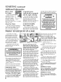
if you follmv the normal
starting procedure, you should
have no problem starting your
tiller But, just in case you do
have problems, heros what to do.
Make sure dae oh switch is on !
"start" Youd be surprised how
many people forget to push the
s_4tch into tim "!" position
If the switch was on "o" when
you pulled the cord, you may have
flooded the engine
lever,
your tiller awa}qlet it idle {bra minute to
give the engine a chance to coot down
If you follow the steps above and
}:our engine still won't start, try this:
1 Push the switch to "l"
2, Push in the choke button to open
the choke,,
3 Press the plastic bubble a few times
4. Give the starter cord a few short,
quick pulls The engine should start
and run
5 tf the engine does not start, then
pull out the choke button to close the
drake Putl the starter cord four to five
times. The engine should sputter or
cough.
6 After the engine sputters, push the
choke button in..Then pull the starter
cord. The engine should start and run.
7 If the engine still does not start,
repeat steps 2 through 6
8. If the engine still does not start,
call your local audmrized MANIIS
dealer.
IMPORIANI'
NOIE:
Never use starting fluids. Starting fluids
will cause permanent
engine damage.
Using them will -void the warranty°
IMPORIANT
NOIE:
Before you ttse your MANrlS Tillet;
read the Safety Rules & "Warnings on
pages 3-4.
GETTING
YOUR
TILLER
TO
YOUR
XValk it.
rake It for a Ride.
Once your tiller is running, you can
"walk" it to your garden ,Just press the
throttle lock out button and squeeze
the throttle lever gently and let the
tiller _tip-toe" across }'our yard on its
tines tt won't hurt your lawn or
drivewa}_
You can easily transport your
MANTIS Tiller to a friend's or relative's
house just empty the fuel tank (This
is crucial,) Then stow ),our Tiller in
the trunk of }'our ear or truck tt fits
easily And you can put it in and take it
out without straining your back
Carry
GARDEN
it.
Make sure the engine is off. Then
use one hand to grasp the convenient
carrying handle. Use the other hand to
hold the handlebars. (Picture l) Then
lift );our tiller and carry it to your
garden.. Since it weighs only 20
pounds, it won't strain your muscles or
tire you out!
Picture
::: waRmN a
:
NEVER CARRY YOUR TILLER
1
Picture
2
:
AS THE PERSON IN PICTURE 2 IS DOING.
i:: IF YOUDO,YOUWILLSUFFER : :
: i:: :: :SERIOUSINJURY,
i
TILLING
Now You're Ready to Use Your
MANIIS Tiller.
if you've seen other tillers, your MAN rlS
Tiller may surprise you tt tills best when
you pull it backward! You see, when you
pull your MANTIS Tiller backward, you
give extra resistance to the tines, so they dig
deeper (Picture 1)
Picture 1
Vv'hat_more v,,hen you go backward, you
erase your footprints So your soil stays
light and fluff_,;With other tillers, by
contrast, you walk right over the soil you've
just tilled, packing it dmvn, so it_ less
plantabte..
Run Your MANTIS
Tiller like
a Vacuum Cleaner.
Picture 2
Place your Tiller at the head of the row
or area you want to till. Start it up Then
use an easy rocldng motion First, pull },our
Tiller backward Then use an easy rocking
motion Again, pull your Tiller backward.
Then, let it move forward just a little bit
Then pull it backward again.. This wil! help
you till deeper
Keep repeating these steps until you've
tilled an entire row..Start again on the next
tow It's much like running a vacuum
cleaner! (Picture 2)
You Can
Even
For Deeper
Tilling:
Control
Depth.
Move your Tiller slowly back and forth.
as you would a vacuum cleaner Work ttae
same area over and over until you've dug to
),our desired depth (Picture 3)
For Shallow Tilling:
Switch the tines to the euhivating
position (See page 10 to learn how) Then
move },our Tiller quickly over your soil
surface.
For Big Weeds or Tough Roots:
Let ),our Tiller rock back and forfla over
the tough spot, until the tines slice
through the weed or root,
"four IdA_NTIS Tiller Handles
Special Tilling Projects.
Want to turn part of your lawn into a
colorful flower border? Your MANTIS Tiller
makes it e,'k_y! Just run your Tiller back and
forth until the sod begins to break up Then
continue tilling. Your Tiller will chop the
clumps of sod until they're fine,. Then, it
will work them into the soil. Pret W soon,
you'll have a soft, fresh planting bed
Picture 3
9
TILLIN G/CULT ATIN
II
G
How about a family-size
tractor or big tiller to break ground
for you This is a one-time-on|y
investment that's well worth the
sma!l cost
vegetable garden?
Nowadays many gardeners prefer
I_ENTANGLED, SHUT OFF THE ENGINE AT
ONCE: REMOVE
il' ONCE:
REMC VE THE
THE SPARK
SPARK PLUG
_LUG WIRE
WtRE
THEN REMOVE
II i _THEN
RE_ OVE THE
THE OBSTRUCTION
OBSTA?UCTION
WHILE THE ENGINE IS OFF. NEVER: TRY
|] _ WHILE THE t!NGINE IS OFF. t lE_E2_ TRY_
_ TO
11 1_I
TO REMOVEAN
REMI)VE AN OBSTRUCTION::
OBSTRL CTION . I
: _i
li ::_
_:I WHILE
WHILE THE
TI- E ENGINEtS
ENGINE tS RUNNING_
R_.WNING, :ii:
:i
::
SERiOUS INJURY CAN RESULZ : ::I_
small gardens -- especially in the
suburbs, where space is at a
premium
But, if you're fortunate
enough to own a large tot, you can
create a bigger garden -- a half acre
or more Heres how:
i
YourMANIIS riller Makes
Weeding a Pleasure!
As a tiller, ),out _£_NTIS Tiller
works the soil down to 10" (254 cm)
deep But, as a cultivator, it gendy
cultivates the surface, only 2 _ to 3"
(5 09 em to 7 62 cm) deep
1 Fixst, hire someone
2. Ihen, use your Tiller to break
up any remaining chunps of soil or
sod Unlike a tractor or big tilter,
},our MANTIS Tiller is a precision
toot It will puh, erize ),our soil into a
smooth seed bed
with a
The result? Your Tiller will cut ),our
weeding time in half, and turn a
tiresomc chore into a pleasure.
How to Switch From Tilling to
Cultivating Position
1 Make sure your Tiller is off
First, you must change the tines to
the weeding position This takes less
than a minute.
2 Remove
the tines
1"hen, your MANTIS Tiller's sharp
"tine teeth" witl slice up those pesky
weeds, burying them as you go along
And, since the tines in this position
won't dig too deep, they won't hurt
your plants' precious root systems.
4 Place the right-side tine onto the
left-side axle Place the left side fine
onto the right-side axle. The "D" hole
should be to ttmeoutside
3. Remove
the retaining
pins from
the tines from the axle.
5 Here is how to make sure you've
installed the tines properly Stand behind
Picture
I
Picture
2
the Tiller and hold ),our hand, palm up,
next to the tines. Do the tine points
curl up, as your fingers do? If so, they
are in the corrcct cultivating position
6 Reinsert
the pins,
CULIIVATING
Now You're Ready to
Cultivate or Weed.
Fuel
Guide your Tiller where you
want to weed and start it up
Pul! your 'Tiller backward
slowly, then let it move forward
a bit, in a gentle rocking
motion. Watch it slice, sttred_
and bury those weeds!
:
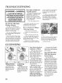
'Iilling
Position
Tine teeth point in the
same direction as the
rotation of the tine; or
toward the front of the
Tiller; away from the
operator.
10
Fmntl
Cultivating
Position
Tine teeth point in the
opposite direction as the
rotation of the fine. Tines
point toward the back of
the tiller, or toward the
operator
Got tough weeds? Lighten
your pressure on the throttle to
slow your Tiller down Then
work back and forth untiI your
'Tiller chops up (he weeds ItS
easy and effective!
Remember, any tiller "a411
tangle in tall grass, string),
vines, or super-big weeds, So, ff
you have a "backyard jungle,"
first use a knife, pruner, or
brush cutter to chop up the
overgrowth. If the tines become
tangled anyway, push the
switch to the "o" position to
turn rite engine off completely
before trying to clear them
'The optional Tine Detangler
(Item #1322) wqll clear tines in
a jiffy Call your local authorized
MANTIS dealer.
Your MANTIS
"Will Weed
Narrow
Iiller
Between
Rows!
Your MANrlS Tiller is a
precision weeder that easily fits in
tight places. So don't be afraid to
weed anywhere: between plants
and shrubs; in comers; against
fences; on raised beds; in _qde
rows; even in very narrow rows
Your MANI IS Tiller weeds six*
to nine inches wide_ So you can
run it in a tightly ptanted garden
without damaging your' delicate
plants. Tb2t's good news for
suburban gardeners, who often
have to plant rows close togedaer!
*XvWlthoptional Planter
Furrower attachment
(Item #6222 )
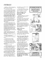
Check
the Air Filter
Often
A wet or dirty air filter can affect the
way ),our engine starts, performs, and
wears So, it's a good idea to check your
air filter once a month
If you work in dust_' soil, or if you
want to be on the safe side -- then
check ),our filter more often (for
instance, befme each use) But be sure
to replace it at least once a yeai; in the
spring or fall. Clean or change it as
needed. It is recommended to change
the air filter ),earl)',
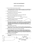
of fineair-cleaner cover. (See Picture I,
or look up Key #1 in Air Cleaner Parts
Assembly on page 1.7)
2. Take off the covet:. Make sure to
clear the choke button_. (Picture 2)
Order a new one directly fi'om our
Customer Service Dept Call 1-800366-6268
3. The air filter is the pad on tire
inside of the air-cleaner cover Check
whether it is soiled or moist,
IMPORIANI!
Make sure filter
is "sealed" properly in the
cover. The filter must fit
snugly inside the rim that
holds the Falter in place°
7. Insert ).'our clean filler inside the
air-cleaner cover
4. If the air filter needs cleaning or
no longer fits propefl); remove it Just
lift an edge carefully and 'peel" it out
(Picture 3)
installing the filter incorrectly will
cause engine damage and void the
warrant): Fit the cover back over the air
cleaner (Again, make sure to clear the
choke button )
5 Use a brush to remove debris
flora the pad.
How to Check, Clean and
Change the Air Filter
6. If the air filter is so dirt}, that it
won't crone clean, you must replace it
or severe engine damage wilt occur-
1 Loosen the wing nut on the side
8 Tighten the wing nut to secure the
cover
Note:
Please check the lip on the Air Cleaner
Covet. if the lip is chipped or cracked,
it should be replaced. This will prevent
dirt from being ingested through the
carburetor into the inside of the engine.
Picture
I
Picture
2
Piclure
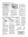
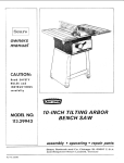
How to Check the Grease
Level inside the
Worm Gear Housing
3
the top of the housing If it doesn't, add
lithium #0 grease (Item 9985) This is
the only way to add grease to the worm
gear housing, (Picture 2) To purchase
MANTIS grease, call your local
authorized MAN rlS dealer.
"Whenwe built }'our MANTIS Tiller,
we lubricated the worm gear housing
thoroughly,
Please do not overfill. Too much
grease can create pressure, which could
cause seals to fail or the clutch to slip
It is imperative that you inspect the
grease level once a )'ear, Simply remove
the cover plate on the worm gear
housing (Picture 1) Then check to
maim sure the grease comes ahnost to
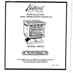
Fuel Filter Replacement:
Fuel filter' to be changed at the end of
credo"season
Clear Blockages From
the Fuel Line & Filter:
After you've used your Tiller for a few
seasons, d_eck for blockages in the fuel
tank and fuel filter Such blockages can
keep your Tiller from st.arting
Clear any blockages you see in the
tank, fuel filter, or fuel line. Remember:
The fuel filter is located inside the tank
(See Picture 3) Then use the normal
starting procedure to start your' Filler
:::: ::::Zi:
Picture 2
Picture
3
11
MAINTENANCE
(contimled)
Then stop the engine after it
reaches operating temperature.
What
En_ne
Now, turn the RED, high-speed
screw counter-clockwise
all the way to
stop . Then turn the WHITE, low
speed screw halfway between the
counter-docl_vise
and clockwise stop
positions
to Do if Your
Idles
too
High
What if your engine runs too fast
or if the tines turn the instant you
start the Iiller? You may need to
adjust the idle screw (Key #19 under
Carburetor on page 17) by itself right
below the H and L screv_.s. Gently turn
it counter-clockwise
lbu'll know
you've adjusted it correctly when the
axles do not turn at low idle.
What to Do it Your
Engine Runs "Rough"
If },our engine runs "rough" or
statts_ you may need to adjust the
carburetor and idle screws
Picture
Now restart the engine
carburetor adjustment
t
If you remove the air-cleaner cover,
yon'It see the two carburetor,
adjustment screws next to the choke
button. (Picture 1)
The "RED" screw is the HIGHspeed adjustment..rtae
"WHITE"
screw is the tow speed adjustment
First, remove the tines fl_om the
axle. Then start engine, Let it run for
two to fl_ree minutes, "FLASH" the
choke several times during the warmup to clear any air from the Fuel
system
Run the engine at full speed two or
three seconds Io clear out any excess
fuel Then return to idle
No_; accelerate [he engine to full
throttle several times to check for a
smooth transition from idle to high
speed
If the engine hesitates turn the
WHITE, low-speed screw counterdockwise one-eighth of a turn, Then
accelerate the engine.
Repeat the adjustment until you get
a smooth transition to high speed
4, Behind flae exhaust
guide (Key #25) will be
the muffler gasket (Key
#24) and inuffler screen
(Key #23). The screen
sits under the gasket
Cleaning the
Muffler Screen
t, Take out the spark
plug
Picture t
Note how the engine
doesn't six al! the _,ay down on the
tt_nsmis_.ion,
How to Reseat
the Flange
At some point, you may find
that the tines won't turn when
you press the throttle This may
mean the enDne isn't sitting all
the way down on the worm gear
housing
Pertaaps you've been using
your Filler for several },ears.. Or
perhaps you've removed the
engine for use with our hedge
trimmer attachment,
then
replaced it, In either case, the
flange bolt (Key #38, page !8)
may have come loose and lifted
the engine up,
If this happened you'll
notice a gap between the
bottom of the engine clutch
case (Key #37_, page 18) and
12
Picture 2
Note how the engine
the way down on the transmission
sits all
the top of the worm gear
housing (Picture 1)
_b fix this, loosen the flange
bolt Take the engine off fl_e
worm gear housing Notice the
hex head on top of the drive
shaft (Key .-"-9,Page 16). Inside
the clutch case, you'll find the
clutch drum (Key #31, Page
29). Make sure the hex head
lines up with the clutch drum
inside the clutch case
Then put the engine back on
the worm geat housing Make
sure the plastic carrying handle
is not under the fue! tank,
If you've followed these steps
properb; there _411 be no gap
between the clutch case and the
worm gear housing (Picture 2)
Make sure you tighten the flange
bolt!
to finish the
2, Remove the red
cylinder cover, (Key #32)
which is held on by 2
phillips-head
screws,
(Key #33) and 1 hexhead screw (Key' #34)
which you will need an
allen wrench to remove,
5 If the screen (Key
#23) is clogged with
deposits, it needs to be
cleaned Use carburetor
deaner, and any brush
that is not metal Brush
the screen until you are
able to see through it
3 You _,ill see the
metal exhaust guide, held
on by 3 more phillips-head
screws, (Key #26) Remove
the exhaust guide
6. If the screen
remains plugged after
attempts at cleaning, it
nmst be replaced
9
STORAGE
Each hlt -- or before you store your
MANTIS Tiller for an)' long period -- be
sure to take these measures:
1 Do not store your Tiller with fuel
still in it Even under ideal conditions,
stored fuel containing ethanol or MTBE
can start to go stale in 30 days And,
since stale fuel has a high gum content,
it can clog the carburetor, this, in tmn,
will resuict fuel flm_: So, when you're
ready to store your Tiller, or will not
be using it for more than 2 weeks,
drain the fuel tank completely, (Picture 2)
2. Next, restart the engine to make
sure no fuel is left in the carburetor.
Then run the engine until it stops lqais
wilt pre_ent gum deposits, forming
inside of the carburetor and possible
engine damage.
3. Disconnect spark plug wire and
remove the spark plug (Use the wrench
that comes in our optional Hand}, item
Kit, Item #8444 Or use a 19mm or 3/4"
spark-plug wrench.) Pour about a
teaspoon of clean, air-cooled, two-cycle
oil through Ore spark-plug hole into the
combustion chamber (Picture 3) Leaving
the spark plug out slowly pull the starter
cord two or three times to coat ttae inside
of the cylinder walt
4.. Replace the spark plug with a NGKBPMSY A replacemem spark plug is
included in the optional Handy Item Kit
item # 8444.
5. Install the spark plug, but leave the
spark plug wire disconnected
6 Clean the air fitter as described on
Page t I.
7 Clean dirt, grass, and other
materials fi'om the entire machine..
8. Wipe the tines with off or spray
them with WD-40, to prevent rusting
9. Oil the throttle cable and all visible
moving parts. (Do not remove the
engine cover..)
10. Replace the fuel filter.
11.Check the grease level in the worm
gear housing, as described on page I 1
t2 Order new parts to replace any
that are badly worn or broken..Just call
,*'ourlocal authorized MANTIS dealer.
13 Store your TilleL in an upright
position, in a clean, dry place You can
store with the bandies in an extended
position or folded down. (Picture 1)
14 To fold the handles, follow these
easy steps: Loosen tim handle knobs
(#40), fold the handles forward (see
picture 1, inset) "i'ighten knob securel}:
Your handles are now foIded and ready
to store in a smaller area
A WARNINO.DANOERA
t5 Do you have fuel Iefl over from
last season? Dispose of it properly Buy
fresh oil and gasoline next season
DO NOT STORE IN AN AREA
WHEREFUEL FUMES MAY
i ACCUMULATEAND REACH A
: :: :FLAME OR SPARK.
How to Prepare
MANTIS
Tiller
Your
for
Restarting
Unfold the handles into an upright or
extended position Tighten the two
handle knobs (#40)
In the Spring. when you take },our Tiller
out of storage, remove the spark plug..
Pull tire starter cord three or four times
to clean oil fl'om the combustion
chamber
(Picture 4) Wipe oil from tile spark
plug. Place the spark plug back into the
cylinder Re-connect the spark plug wire
back on tile spark plug. 7"hen follow the
steps on pages 9 & !0 to refuel and
restart },our Tiller
Again,
Check
Carburetor.
(
the
If },our Tiller won't restart in the
Spring -- or if it lacks its usual power
due carburetor may need attention..
Follow tile steps on page 19 for adjusting
the H and L screws (Picture 5)
Check
Picture l
the Spark
Plug
Picture
2
Pic;ure
3
Too.
If your Tiller won't restart, or if it
lacks full power, the spark plug may be
at fault Check to see if the plug is
fouled with oily black deposits Clean or
replace it if it is (Picture 6)
Also, check whether the center
electrode is rounded at the end,
or' if the ground electrode is worn If
either is the case, you should replace it
with a NGK-BPMSY spark plug Use a
19mm or a 3/4" spark-plug wrench to
install it, Adjust the plug gap to ,024 028 in, (0 6 to 0 7 ram)
Caution:
Do not over tighten
the plugo The correct torque is 18 to
22 ft-lbs (24-30 n m)
IMPORTANT
17oavoid
threads,
the plug
t3,Iinder
NOTE:
possible damage to the
do not try to remove
from a hot aluminum
head.
Picture
Picture5
4
Picture6
...................
:AwanmNaA:: : : II
:always make sure the handle
i:: i ::::knebs are secure before
::starting your MANTIS Tiller.
II
II
I]
I
13
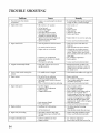
TROUBLE SHOOTING
ProMem
Cause
Remedy
Engine is not seated properly on the gear
housing
• Rednsta[t engine follo_ving the instructions
on page 12 (How to reseat the flange)
l, Tines don't turn when throttte
is depressed
.
2
• oil switch is ill "o _'position
•
Move switch to "l "
•
•
"
•
•
No fuel in tank.
Fuel strainer clogged
Fuel line clogged
Spark plug shorted or fouled
Spark plug is broken (cracked
porcelain or electrodes broken)
• Ignition lead wire shorted, broken or
disconnected from spark plug
. Ignition inoperative
•
•
•
•
.
Fill Tank°
Replace Strainer
Clean fuelline
Install new spark plug
Replace sparlt plug
•
Replace lead wire m attach to spark plug
•
Water in gasoline or suale fuel mixture
•
•
Too much oil in fuel mixture
•
•
Engine under or over choked
•
•
•
CarburEtor out of adjustment
Gasket leaks (carburetor or cylinder
base gasket).
Weal:. spark at spark plug
•
•
If flooded by over choking proceed
according to instructions in operation
section If under choked move choke
lever to closed position and crank two or
three times,,
See "Carburetor Adjustment"
Replace g_kets
•
Contact your local authorized dealer"
Fuel tank vent line is not in an
upright position,
•
Return the fuel tank vent line to the
upright position and place it under the
cylinder cover in the small "pocket" ill
the cylinder cover
3
Engine fails to start
Engine hard to start
•
4. Engine
continuously
floods
•
_5 There is black smoke coming from .......................
" Tt_e muffler screen is clogged
exhaust
• Comact )'our local authorized dealer
'.
Drain entire system and refill with
fresh fuel.
Drain and refill with correct mixture
Clean carbon from multler s'creen (page 12)
6. Engine misses.
• Dirt in fuel tine or carburetor
, Carburetor improperly adjusted
* Spark plug fouled, broken or incorrect
gap setting
, Weak ot intermittent spark at spark plug
• Remove and dean
• See "Carburetor Adjustment."
• Clean or replace spark plug - set gap to
024- 028 in (0.6-0.7 ram)
• Contact your local authorized dealer
7, Engine laclcs power
*
.
.
•
• Spark Arrestor Clogged
• Poor compression
• Clean or replace air filter.
• See *'Carburetor Adjustment"
• Clean carbon from muffler,
. Remove muffler, rotate engine until the
piston is at top of cylinder With a
wooden scraper or blunt toot, remove all
carbon from exhaust ports Be careful not
to scratch or damage piston or cylinder
wails Blow out all loose carbon with
compressed air Install muffÊer and gasket
• Clean Spark Arrestor
• Contact your Local authorized deMer
,
Insufficient oil in fuel mLxmre
•
•
Air flow obstructed
8. Engine overheats.
9. Engine noisy or knoeldng
, Spark plug in incorrect heat range.
• Bearings piston ring or cylinder waits
are worn
I0 Engine stalls under toad
.
14
Air fiher dogged.
Carburetm out of adjustment
Muffler clogged
C,togged exhaust ports
Carburetor adjustment too "lean,
Engine overheats
MLx fuel as described in starting
instructions
° Clean flywheel cylinder fins and screen
•
•
Replace with plugs specified for engine,
Contact your local authorized dealer
• See "Carburetor Adjnsunent
. Remove dust and dirt from bet_een fins
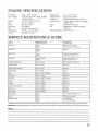
ENGINE
SPECIHCAT ONS
Dry Weight ....
"F,_peof Engine
, ,
Rotation
........
Bore ...........
Stroke
.......
Spark Plug
Fuel ................
Fuel Oil Ratio
....
....
Gasoline
28kg -- 6 lbs, 3 ounces
Air Cooled, "l_vo stroke, Sin_e-Cylinder,
Gasoline Engine
Cloc!_vise, viewed from TOP
322 mm (1,268 in )
26 0 mm (1 04 in )
NGK, BPM8Y
Premixed two stroke fuel
50:t ratio with MANTIS oil
Unleaded
SERVICE
Displacement
Exhaust System
Carburetor .......
Ignition
System
Starter
......
Oil .............
Fuel Tank Capacity,
21 2 cc (1 294 cu in)
Spark arrester muffler
ZAM_A_
diaphragm model C1U type
Flywheel magneto, capacitor discharge
ignition type
Automalic rewind type
Designated, two-stroke, air-cooled
engine oil
051it (17,0oz)
(see page 7)
MAINTENANCE
GU!ID F
Area
Maintenance
Frequency
Air Fitter
Clean
Replace
Daily or every 4 hrs use
Eve U 3 mfl_s or 90 hrs use
Fuel Filter
tnspecl
Replace
Monthly
Spark Plug
Clean
Replace
Check / Rebuild
Replace
EveW 3 nuhs or 90 hrs use
16 months or 270 hrs use
]6 months or 300 hrs use
Yearly or 600 hrs use*
Cylinder Exhaust Port
Inspect t Clean
Every 3 mills or 90 hrs. use
Cooling System
Inspect I Clean
Before Use
Moffler (Spark Arrestor)
Inspect/Clean
Monthly
Gear Housing
Check Grease
Yearly
Tines
Inspect I Clean I Lubricate
After Use
Inspect/Repair
Before Use
Fasleners
Inspect 1 Tighten t Replace
Before Use
Labels
Inspect I Replace
Before Use
Handles
Inspect t Replace
Before Use
Guards / Safety Devices
Inspect t Replace
Before Use
Fue! Line
Inspect I Replace
Monthly
Inspect / Replace
Monthly
Replace
Even, 3 mths or 100 hrs use
Check
With each re-fueling
Clean
Replace
No maintenance
For coil and flywheel
Carburetor
Fuel Leaks
Starter Rope
FueI Strainer
Choke
Ignition System
Replacememwill be required for commercial use after 600 horn's For Consumer use. cleaning eve_"6 months is required Cleaning includes RebuildKits
IMPORTANT:
Time Intervals shmxm are maximum
Actual use and ),our experience will detem_ine the frequency of required maintenance
Notes:
15
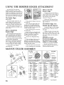
USING
THE BORDER
EDGER
ATTACHMENT
Your MAN-US Tiller has been
designed and bulk to accept a wide
range of MANTIS Tiller Attachments
to
increase its usefulness in your lawn and
garden. And, all MANTIS'Tiller
Attachments have been designed for quick and
easy attachment to the Tiller or Engine
How
Border
Piclufe
rhe most popular attachment,
the
Border Edger can be used to create
clean, neat edges along walkways, or
around trees, shrubs, and garden beds
the Border Edger has two parts: a
_heel and a hardened steel blade, with
pointed tines
How to install
Border Edger
the
The following instructions refer to
"riglW' and "left" axles Assume that
youre standing behind },our Tiller, as
you would for tilling and cultivating
Some areas of },our yard may harbor
roots and other underground
obstructions In places like this you'll
want to edge your borders shallowly
(1" to 2" deep) Here's how to install
the Border Edger for shallow edging:
1 First remove your tilling/
cultivating tines
MANTIS
TILLER
the
Edger
1, Position your MANTIS 'Tiller so
that the Edger blade is right along the
garden edge and the wheel is outside
(on the lawn, on the sidewalk,
wherever) (Picture !)
The Border Edger
(llean #3222)
to Use
Picture 2
1
2 Then slide the Edger's wheel onto
the right axle
3. Now slide the Edger blade onto
the left axle. The blade's angled face
should hit the ground when you spin
the blade forward; do not operate tiller
without tine pins in place
4 Insert retaining pins on both left
and right axles
Around walkways and garden beds,
you'll want to edge more deeply (3" to
4" deep) Here's how to install the
Border Edger for that purpose:
! Remove the titling/cultivating
tines
2 Slide the Edger's blade onto dae
right axle. The blade's pointed face
should hit the ground when you spin
the blade forward; do not operate tiller
without fine pins i,nplace,
3, Slide the wheel onto the left axle
4. Insert retaining pi_ on both sides
2, Start ),our Tiller and pull y,our
MANTIS backward along the garden
edge (Picture 2)
'The Border Edger Can
Handle Special Projects!
I Install the Edger for deep ed_ng,
as directed above, Then use it to cut
sod strips
2 Edge and weed at the same time!
Just attach the Edger blade on one axle
and a Tiller fine on the other axle, "Mix
and match" blades; don't be afraid to
experiment,
IMPORI'AN'r
NOTE:
If you do a lot of edging, you'll
appreciate the MANTIS _Vhed Set
(Item#9222,) It gives you added
stability, for even easier handling.
To order the Wheel Set, or any
MANTIS Attachment, call your local
authorized MANTIS dealer
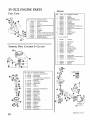
ASSEMBLY
PIN 438LA
.....
PIN 438RA
DIRECTION
DIRECTION
Raised Hub
_MVan_u k_k at "{h*ewith _h¢ mi'_!d hub Iaeirlg you
and _he €_c_I__rr pointing m a COUNF.ER CLOCKWISla
!olallcm, )'oll arid a RIGIIT I/AND "FINE.
i
16
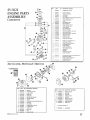
l'ff_
NA_{_ O"ffMA'ff_=At
1 400254 1 TriggerHandle
Assm, RH
2 400255 1 HandleAssm.LH
3 400224 2 Lower HandleFoldDown
4 400620 1 Lab01
5 148
I Handle Brace
6 478
2 ThrottleCllp
7 4_5
I FenderGuard
B 400908 I EngineAssm 8V5012
"9 468
I Drive Shall
!0 466
I WormGear
Houstng
11 435
I Gasket
t2 437A 1 Housing Cover
t3 551
4 R{I HR Self
Tapping
Screw
14 _23
I Roller B_aring
i_t lilal,,te
QFY _AT_BIAL
15 425
2 Worm Bearing
Race
16 424
1 Worm Thrust
Bearing
17 422
1 Worm Shaft
18 426
1 Worm Disk
19 428
1 Ret_ir_ingRin0
1 Worm Gear
20 429
21 431
t _io_Shaft
22 430
2 WormGear
Thms_ Washer
23 432
2 Worm Gear
Bearing
24 434
2 Bearin{i Seal
25 435
2 Searing Seal
Relai_r
2li438RA I Tineassm (RT)
27 438LA I TreeAssm (LT)
2B 418-1 2 T_noRemlning
Hair Pin
Iffu
2B
30
3t
32
33
34
35
36
37
3B
39
40
41
42
NA_ D_x
400218 1 Carrying Handle
4B7MA 1 En_iaaLabel
4043
1 Tine Label
45B
1 Roller Bearing
a05B 1 Manlis Label
4t0
2 Cap Screw1/420x 1" LG
972
4 Lock Nut 114.*25
470
2 1/4 '-20 x 3" Bolt
140
2 Bolt 1/4-20 x
3/8 _ kg,
377
2 HandleClamp
400509 2 Boll
400510 2 Knob
400230 2 Plug
400010 t Transmission
Assm
" Also in Key #42
[rrE_t
5V-5C/2
P.4_XT
QTY
l
ENGINE PARTS
ASSEMBL
S
!
O.
+
CARBURETOR
CARBURETOR - CIU+K_2
pgq50"i','%_i
SC_I£_,\L
PURGE |I:_SE
1_35R1_660
PUMP, PURGE
2
3
DF_qCRIPT|ON l |{Ehb\lll-k_
IkL_AINER. PURGE PUMP
4
IIASE.
I'L:I,'GE
5
ilODY.C_RBURV.IOR t NOt'AVAILMHt_ S};|*AK_FF-iX
_CREW MF:'ff:I_'INGId_\ ER MN
7
I25_76D|2tl
NOZZA5 Oil.OK VAL',Z
SWIVEL
9
|_327D93ti
CLIP, _IUFI!.E
t0
P_5I_II,70
SHA F"f,THRDTH,,F.
12
IL_314139311
SHYING THROTIIJ_:llJffUl_'X
_CREW <I'HR(JITI&VALNE
13
12531_0
14
125_2115130
s H.ad_
VALVK TIil_OTn,F.
C_I! lllllL_
SIIAF}"
NEF.,DLE
-LOll'SI>_
P- 'i
@.%
CA£ M_¾TLII,ELLMITER -LOW ._I'12_D
12552013310
1t_
1Zt3_9391)3t)
20
12533300'_
SFRING, IDa.EADJUST
_t
1_32412112|)
COVEK FUEL I'UMP
22
I !_€3 II)l 2_20
SOO]W FUEL I%tMPCOVI_
SC_
23
l_]l_tl
Jillt
V,10_'_. ADIUST
I
RH%I_
74
.......
1
DLII_HRAGhf,
_+_
.........
}
GASKET,
1
PiN, ML'_,RL\G
1
LEVER.
Mh"FF2(1NG
)
%%LVL
INLET
}
STq'dNG
|
5_L4IlqER
!
DIAP1 _',IG M< l'_
1
GASKEL
I
GASK_._I
I
DIAPHRAGM
Z¢,
Q ;'.9"
0
NIE'OL£. 111¢311
5|'t_ED
CAP, hlIX-H;'RE I.IMI'H'_I
,IIIGII
gPH:2)
I;
27
2_
...........
29
31
..........
32
33
,_
.........
1k€303t312€1
35
KIT HNO.UDF.I
_M_
21-3_
M_JIING
DIAP|ID%GM
METERING
_VER
.%_E13 LaX
MET£RING
L_VER
PUSL"
VUEL PUMP
M'II_.4fiM
KIT ! INCLUDES
H'P,;",I_ ]5-3ti
METHtlNG
36
.............
I
GASKh-]_ >MT_I_NG
37
..............
i
D_d+fL_\_,M,
3,q
..........
I
GASKET
FU_
HIH.
DF%pIIK-\UM
PUMP
PUMP
@
/
GASKET KIT
0
I _52gl0105
WING NLrl '
2
COVEP./dR
I,dlcatc_:
New Plla
IIEM
C[,_xdq_{
PART #
QTI', DESCRIPTION
Vlt_|_6_
I
StlIEM% EXIIAUST
,t_@tl_!l
!
MUFt%EIt
I
EYE PD\TE
LM]EI_,CtlOKE
It
4 I3031_4560
HLTER,AIR
20 VI5(DO[1371
5
_.K_5057
SCREW' 5X_S7
2l
6
130-111915360
BRACKET. AIR CLEANER
7
17_5|5_43b0
SHLrfTEIL CHOKE
17_151600S30
SPACF.R
13030t045b0
CASE AIR CLEANER l ]NCLUDES ITEM I0
I1)178_ HIO3230
GROMMET
il
1785 |_,YO-tS_
P,OD> CHOKE
t2
AiR10010_
CARBURETOR
Xl
* N
:2fi
- CIU.,K_
13 t300|€_D31
GASKET, IN+fAKE
14 9_23_051)20
SCREW fX20
15 t30017,I-=.1)3t
IRSUt_7OR
16 1_;O5r£K)0¢_05
Ntrf5
17
SHIELD. IN'TAKE
13Ix11012032
:
/ REMARKS
* l_
3 8tJ012147530
9
BOLD
131t32fi11522
X'347tDIEI_
4
WASIIF_I CONICAl,
90010505055
2
BOLT 5X55
145_62411(:,3fl I
SCREILN, MI31=G,ER
VI040011072 I
GASKF71] EXIIAUh'T
A31_<)_
1
GUIDE, F2GIAUS'[
_13670,,I012
3
SCREW4XI2
Alsll
l_¢I_ded in G.ASKEI KIT
27
I_121009110
1
GASKET KIT
17
SV-5C/2 ENGINE
FUEL
PARTS
BLOCK
TANK
11T..,M
PART #
_)|621Np.2
I
2
:",A
.*(.N
101}3
_
"I;MgK_FUEL l INCLUDES FF_'M 2
2
Dt0452_230
SPAO._
3
_CO27505015
4
V47100C30
SCRE\v 5X15
PIPE. IqJEL * 3._N 210MM /BULK OFI'ION: +J_14
5
V137(D_t0_11
GROMMET
fi
1320t3N0_,20
7
I3t2_fi0732n
ffL1P
FI L'I3N. NJ_.
8
A._5(_ffl0030
VALVE OtF.EK :
_l
130t! I0_153t_
o..,I P,PIPE
V471N)t2_/
PIPF..ViLN't,,3XSX_IMM I BULK OPTION: *A._l)
14
to
0
i,J,,,i,,J,,llJiiiiiJiJJiJiJi/,JiJJi/iJl,i,J/ll/luJu
ull,i, JJlUlJ,iJJJ,
12
131[XLI{I_JG_t
FUEL 'E-kNKCAP ASY ! INCLUDES rl_!
13
1310ff55gN_
GASKEI FUt'_.IANK t"&P
la
131t_qStO3_
CONNECtDIL FUF,L Tb2ffg CAP
iiilullJ,
,JJ ,
,
i
SrARIEr, PAWL CAICItF.R & CLurot
o-?
CYUNDER
1
GASKET CY]dlWOER
4
I_21{_7712
|
PI_FON, KIT I INCLUDES [TF_IS 5-_
5
A 1010P_0'_
i
1
RING, PISTON
HN, PISTON
IO(F315[kl63_
2
CtRCLIP, 1'IS-IONPIN
|rllXll4
i 15213
2
SE_(2E,R, PIS_rONPLN
AOL1011_390
I
CIU%NKSILA
FT ASY / LNCLUDFN ITBI
1_
V553_1910
1
llF_VRRCG NEEDLE
II
12
1(D2041152 t
t
CK_,SNKCAA'EKIT ! INCLUDES F[I_MS 12-1h
If_2121."11_I
2
Oft, SEAl
1(I0215039.'_0
2
DOWEL PiN
11K)24212_1._0
t
(],tSKEE CRANKCASE
15
_0353520!
2
BEARING, BAt.L
16
9N)I62ILNI2g
3
BOIY 5X2_
7
PART #
QTY
DESCRIPTION
At_t_ irMudcdin GASKEF KIT
11
I'11210091tO
18
h4l 1_10220
(.\OIL, IGNITION
IP
2_}
t)r!OlGZIgO20
15611(_1q20
BOLT 4X20
ttUSHING
21
22
V,I75(_(2".2110
15_112111620
TU_
24
t5(_1101983€I
TERMINAL, SPARK PLUG
SPARK PLUG - ItPM-gY
25
16"?1i21528_0
t.FTAD,IGNFPtON
2fi
6103_02730
WOODRUIT KEY
"7
A_XI0150
FLY WHE..._
2_
2_
!g._iqtS000_
1772021_2_
1
t
SPRING WA.SH-tT_I_
ST,\IW_R I_o\W£ASY t fNCt UiS_"; fl_XtS 3041
M
I,'r721tlI-133_
1772.34t_.2_ff
2
2
PA\VI_STARTER
SPRING_ E-\WL R_71URN
A f(_Xl(_do
t
COVER, CYLINDER
g,_2381U018
_ _o7e4_
2
z
SC'_EW4XI8 ....
SCREW ,txs
U720012_20
I
S"rAI_RASY/LNCLUDESH'F_MSIG-21
16
tT'/221_2{13It
i
SPRING Rt_VIND
17
I'D2154MS0
i
DRUM, STARTER
18
17722(:05530
I
ROPF_ SFAR'FEtl 3MM(It'.4"_ X lIl(kqMM(39d_'I.
19
20
17722742030
17722511120
l
I
GUIDF_IlOPE
.....
STARTER GRIP K1T
21
177724611120
i
ILETAINF..KIIOFE,
_
t_23644330
t
SCREW
1t
9NI238fNOt6
4
SCR_4'4XI6
2,t
I75000ff/531
1
CLUTCHASYILNCLUDF..SfflL\L_;_-27
25
17501605020
t
HUBCt£rrcH
1750180513_
2
SPR1NG.CLLWCIt
27
LTSN}905131
2
StIO_CLU'I'CII
2g
1750190.4630
1:
I_L,'ffE. CLUTCH
29
_A'X36000ffJIO 1
WASHER 10
30
g0080836_!0
l
BEARING, BALL
31
175010Nf!33
I
DRUM, CL[rrCH
32
1750,M81630
I
WASHER, CLt._CH
33
17501411520
I
WAS!tEq_,CLLrI'C[I
34
90023NN012
1
SCREWfX|2
35
9110138{14014 4
SCREn,V4XI_I
36
9_F&_XI5
1
WASIIER 5
37
9Nk'_tS0_,'k't3
I
SPRING %K.\SttER 5
38
I3041611520
1
BOLT SX_
39
61022311520
i
CASf_CLUTCII
BULK Gtrl'tON:
18
_"-_
I REMARKS
15
::
tt_
INt4
32
_3
M
I'IT_I
I REMARKS
......
t
6
PII'F. R t:_IUILN,,3XfiXS(tMMt tlULN O|rllON: _I_tl7
BOLTSXI2
V |O00(K!If_
QTI: D-t-lqCRIPTION! I(EMARt_
1
2
3
*
PART #
1213_. DESCttlIWItlN
6°
1
GASKET KIT
CAP, SPARK PLUG
GASKEI' KIT
O
9_444-flYd00
:
....
:
IC-.-,oii?
I
BOLD hldicatcs New Ihl_
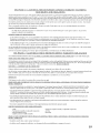
EPA PHASE
2 / CALIFORNIA
TIER III EMISSION
CONTROL
YOUR RIGHTS AND OBLIGATIONS
WARPO, NTY STATEMENT
The Environmemal
ProtectRm
Agency (EPA) and the California
Air Resout't'es Board (C A R B ) and The Equipment
Man'ufacturer
are pleased to explain the
emis._hm control system
warranly
on )mJr EPA Phase 2 / C A R B Tier II1 rot,tie[ _ear 2005 and taler stnaH off road engine (SOREs)
Nc_ small off road engines
must be designed,
buih and equipped
to meet stringent
EI'A and C A.R B, anti-smog
standards
Echo, Incorporated
must warrant the emission eontm! system on
your small oft road engine for the periods of time listed bdow provided
there has been no abuse neglect or hnproper
maintenance
of your small off mad engine
51mr emis,_inn
may be hoses,
control system may inclndc
brits, connecto_
and other
'A_nere a wan'antable
condition
_CTUREWS
parts snch _ the carburetor
emissionm:la_ed
assemblies
exists, the Manufacturer
_ ill repair
or hw.l injected
your
s)s_em,
smaIl nit road engine
and
Ihe ignitinn
s,',slem
and catat)./ic
at no cost m you including
couvertcr.
diagnosis,
parts
Also included
and labor
WA RFc4N'I Y COVE RA_GE:
The 1995 and later small nit mad engines arc _arranlcd
repaired or replaced hy the Manufactt,rer
O_,VNER'S \\{4RRANTY
for two years
if any emission_rdated
RESPONStB|LITtES:
-As the small otl road engine owner, you arc responsible
Ibr _he pcdormance
/vlanufaclurer
recommends
that you retain all receipts covering maintenance
solely for the lack of receipts or for )our tinlure to et_ure the performance
-As d_e small off road engine ownex, yuu should
a part has failed due to ahuse_ t_eglcct, improper
'_bu are responsible
should he completed
regarding
EPA PHASE
This is additional
of the required
maintenance
listed in )'our Opoamr's
on your small off road cnghte,
but the ,Manufacturer
of all scheduled
maintenance
however be av,,'arc thai the Manufacturer
may deny you t\ armmy
maintenance
or unapproved
modificatiom
k)r pre_enting
your small of[ road engine to the Mannfacturer's
in a reasonable
amount
of time. not to exceed 30 days
If yon have any qu_tions
detailed
WHAT,DOES,,,_HIS
part on _,our m_gine is defective the part _ ill be
your
warfare)
rights
and responsibilities,
2 / CALIFORNIA
information
about
WARRANTY
TIER
authorized
ynu
should
contact
111 EMISSIONS
the _ALIFQR
IA TIER
service
center
IILEMISSIONS
iF )our
as soon as a problem
ytmr Product
DEFECT
coverage
Manual
The
cannot den) _arranty
small
exists
off toad engine
The warranty
or
repairs
Manufileturer
WARfO_NTY
DEFECT
EXPLANATION
for your
\VARKANT_
small of[ road engine
COVER?
The Manufacturer
warrants
that your unit was designed
built and equipped
to cnnform with applicable
California
emissions
standards
and that )"our unit is free
from defects in maleria[ and workmanship
that would cattse it m fail to conform with applicable
requirements
withixt five (5) years
The warra)) O, pcrlod bcghts
an the <c the prndnct is ddivered
u) a )€tail l)U)x:hascr This is your emission control system. DEFECTS
WARRANI_f
HOW
\\qLL
A
COVERED
If there, is a defect
PART
in a part cheered
BE CORRECTED?
by this warrant);
a Manufacturer's
Authorized
Sen'ice
Dealer
will correct
lhc defect.
You a:ill not ha_e to pay an)firing
to have the part adjusted,
repaired or replaced
This includes
any labor and diagnosis
['or _arranted
repairs
dealer
tn addition, engine paris not cx'pn:ssty covered under this warranty lint whose,fifihm:
is a result of a,faihac of a covered part will bc wat)amcd
Emissions
System
_epairs
covered
under
this warranty
should
be completed
in a reasm_ab!e
time, not to exceed
performed
by the
30 days
IMPORTANT
If the diagnosis
Vvq_lAT PARTS
DEFECT
reveals
no defect,
the emission
ARE
COVERED
BY THE
defect
EPA
warrant)
PHASE
does not apply
21CALIFORN1A
!IER
tI12005
6,r LATER
SMALL
OFF
ROAD
E,_NGINF.
EMISSIONS
'_LA R1L_'tNTY?
,'An} ,:mission related part not scheduled
repaired
or replaced within the _arranty
for, "required maintenance
'_ (See Engine Operators
Mammt, "SERVICE/x,L4tNTENANCE
SCttEDUI.E")
period
The repaired or replaced part vvi]l be warranted
for the remaining
Emissions
Defect warranty
_'_ill be
period
,An)" emission
related part scheduled
Ior replacement
during "required
maintenance"
(See Engine Operators Matu!e!
"SERVICE MAINTENANCE
SCHEDULE")
is warranted
for the period of time prior to the first seheduld
replacement
point [or that part, An), such part repaired
or replaced
warranty shall be wan'anted
for the remainder
of the period prior to the first scheduled
replacement
point for that part
• Any m;mufacturer-appmved
must be provided without
replacement
part may be used in the performance
charge if the part is still under warmmy,
• An)' replacement
part dtat is equivalent
_varranty obligations
_)f the manufacturer
• The owner
SPECtFIC
is responsible
EMISSION
in performance
for the performance
REI.AI'ED
and durability
of the required
"-NARRANTED
THEEPAPHASE
•At D, Jaihn'e caused by abase, m'gtecl,
•At D,failure
caused
l[;, at)approved
im/nopcr
modifieatitms,
may be used
maimenance
described
maintenance
in non-warranty
in the operators
or repairs
maintenance
on emission-rdatcd
or repairs,
par1.% and
and shall not reduce
the
manual
PARTS:
- Choke
- Fuel tnjectinn Assembly or replaceable components
- Electronic Ignition System
- Calalytie Converler / Muffier Assembly
WHAT 1S NOT COVEREDBY
DEFECT, \VARRAN T32
of any warranty
under
- Carburetor (complete assembly or replaceable eomponems)
Air Filter
- Spark Plug
2/CA_LIFORNIA T!ER,Itl
2005 6z I_4TE_A.
OFF ROAD ENGINE E_:IItSSIONS
mainh:)_ance
use tff u)u)pprm'¢d add.m* 1)artshnodified
parts or unapp)m ed aeee,_aries
19
LIM+_TED WAR +P+4NTT
MANTIS extends this limited warTanty against
defects in material and workmai!sl-dp for a
period of five (5) years [or normal residential
purposes and two (2) years Ibr commercial use
from the date of purchase, to the first retail
purchaser' and each subsequent owner, dining
the warrant'/period,
This warranty covers all
portions of the MANItS TILLER
IviANI IS vail repair or ,eplace, at its option, any
part or parts of the product proven to be
defective in material or workmanship under
nmmal usage during the warranty period.,
Warranty repairs and replacements will be made
without charge for parts or laboc All parts
replaced under warranty x_AI1
be considered as
part of the original product, and any warranty on
the replaced parts will expire coincident with the
ori_nal product warranty If you think your
MAN'tlS 17ILLERis defective in material or'
workmanship, you must send it, along with your
proof of purchase (sales receipt) to:
Mantis
!028 Street Road
Southampton,
PA 18966
Youare responsible [or pickup and delivery
d'lmges; the product must be returned to us
postage paid,
MANIIS assumes no responsfbility in the event
that the product was not assembled or used in
compliance -withan), assembly, care, safety,or
operating iazstructions contained in the Owner's
Manual or accompanying file product; was not
used with reasonable care or requires replacement
or repair due to accidents or lack of proper
maintenance; or was misused, altered, used for
Spocil'icalJons. descriptions
other than normal or'intended purposes 'This
warranty does not cover damage clue to normal
wear and tear,,
You must maintain your IviAN'flS I'ILLER by
following the mah_tenance procedures
described in the o_merb manual, Such routine
maintenance, whether performed by you or a
dealer, is at ),our expense
MANTIS MAKES NO EXPRESS OR IMPLIED
WARRANTIES OR REPRESENTKfIONS
EXCEPT THOSE CONTAINED HEREIN THE
DURAIION OF ANY IMPLIED WAtLRANTY,
INCLUDING MERCt-D_NTABILITY AND
FITNESS FOR A PARTICUI_a_R PURPOSE, 1S
LIMITED TO THE DURATION OF TI-{IS
WRITTEN LIMITED WARRANI_Y MANTIS
DISCLAIMS ALL LIABILITY FOR INDIRECT,
IN CIDEN FAL AND/OR CONSEQUENTIAL
DANLAGES IN CONNECTION "WITH THE USE
OF THE MANTIS PRODUCTS COVERED BY
"IHIS WARRANTY SOME SIATES DO NOT
ALLOW LIMIIAI]ONS ON HOW LONG AN
IMPHED WARRANTY LASTS AND/OR DO
NOT ALLOW THE EXCLUSION OR
LIMII"ATION OF INCtDENIAL OR
CONSEQUENTIAL DM_GES,
SO IHAT
ABOVE LIMITATIONS AND EXCLUSIONS MAY
Nor APPLY 1"O YOU, THIS WARRANTY
GIVES YOU SPECIFIC LEGAL RIGHI'S, AND
YOU MAY ALSO HAVE OIHER RIGHTS
WHICH VARY FROM STATES TO STATE,
MANI"IS
1028
Street
Road
Southampton,
PA 18966
(215) 355-9700
and i!lusIr_tive material in thls _itera_'ure are as accurate as known at the time o! publication, but aro subjoct to change without noltco
_ 2009 Mantis, Division of Schiller Grounds Care lnc,
P/N 401710 1/09
Printed in USA