1
WELCOME
OF NTIS
TO THE V¢O D
GA ENING!
Here's your new MANTIS Tiller...
the lightweight wonder that "Makes
Gardening Easier."
Unlike big tillers, your MANTIS Tiller
weighs only 20 pounds. So it lifts easil>>;
handles smoothly, tilIs and_ weeds precisely
And, unlike other small tillers, it features
serpentine tines that churn soil up to ten
inches deep. It creates a soft, smooth seed
bed, even in problern soil.
Once you know hovv to use your tiller
correctly, we guarantee you'll love it. So
first, please read this manual. It shows, step
by step, how to use your tiller safely Plus,
it shows how the MANTIS Border Edger
can make light work of your edging needs.
If you have questions about any topic in
this Manual, or if you wish to order
MANTIS Attachments, contact your local
authorized MANTIS dealer.
iiiiiiiii
TABLE
OF CONTENTS
Salety Rules & Warnings
...............
Safety Decals ...........................
Engine & Fuel Warnings ..................
Assembly and Mixing Fuel ...............
Starting ..............................
Additional Information
...................
What to Do Just in Case ...................
Getting to Your Garden ...................
Tilling & Cultivating
...................
Tine Positioning
........................
Cultivating
............................
2
3-4
3
4
5-7
7-8
8
8
9
%10
10
10
Maintenance
........................
11-12
Storage ................................
"Double Shooting & Specifications
.......
Service Maintenance
Guide ................
13
I4-1.5
15
Using The Border/Edger
Attachment
........
MANTIS Tiller Assembly Layout ...........
Engine Parts Assemblies ...............
EPA Phase 2/California Tier III Emission
16
17
1.7-18
Control Warranty
Limited Warranty
Statement
..............
Information
............
19
20
SAFETY RULES & WARNINGS
You will notice
understand
throughout
this Owners
and obey these warnings
I. Special
Safety
II. Safety
& "Warnings
Manual
Safety
Rules
and
Important
Notes.
Make
sure
you
for your own protection.
Information
WARNING
The Engine Exhaust from this
product contains ch,._micals known
to the State of California to cause
cancer, birth defects or other
reproductive harm.
PRODUCT
EMISSION
DURABILITY
The 300 hour emission durability compliance period is the time span selected by the manufacturer ce_if_iing the
engine emissions output meets applicable emissions regulations, provided that approved maintenance procedures are
followed as listed in file Maintenance Section of this manual
III. Safety
Decal Information
An imporianl part of the safe b system incorporated
in this tilier are the warrd:ng
and informa[ioi_ decals tbund on various parts of the tiller+ These decaIs must be replaced
in time due _o abrasion, etc. It is your responsibility to replace these decals when they
become hard 1o read. 'Ihe location and part tmmbers (PIN) of these decals are illustrated on Page 27.
P/N 400620
CUTRNG HAZARD; KEEP
FEET AND HANDS NN'AY
FROM ROTAT NG TINES,
DO [',JOTCARRY THE
TILLER iN THS
POSITION
@
CAUTION: WHEN ASSEMBUNG
THE HANDLES, MAKE SURE
FUEL TANK EACESOPERATOR,
THiS IS THE REAR OF THE
TILLER, REFER TO ASSEMBW
INSTRUCTION ON PAGE 7_
READ OWNERS MANUAL
BEFORE USING TILLER, OR
PERFORMING ANY REPAIR
OR MNNTENANCE KEEP
OWNERS MANUAL _N A
SAFE PLACE
DON'T FUEL REFUEL,
OR CH_CK FUEL WHILE
SMOKING, OR NEAR AN
OPEN ELAME OR
OTHER _GNmON
SOURCE,
50:1
.[_1)+_
iNCORRECT ASSEMBLY,
WEAR EAR AND EYE
PROTECT_ON_
MIX UNLEADED GAS
WITH 2 CYCLE 50:10_L
3
IV. Warnings
- Do's
Read and understand the owner's
manual. Pay particnlar
attention
to aIl
sections regarding safety'.
1. Always keep a firm grip o13both
handles while the tines are moving and/or
the engine is running. BE AWARE!! The
tines may coast after throttle trigger is
released. Make sure tines have come to a
complete stop and engine is oil betore
letong go of the tiller.
2. Always maintain a firm tboting and
good balance Do not overreach while
operating the tille> Betbre you start to use
the tiller check the work area for obstacles
that might cause you to lose your tboting_
balance or control of the machine.
3, Thormaghly inspect the area where
equipment is m be used and remove all
objects, which can be thrown by the
machine.
4. Mways keep area clear of children,
pets, and bystanders.
5. Always stay alert. Watch what yon
V. Warnings
- Don'ts
Don't use tiIler with one hand. Keep
both hands on handles with fingers and
thumbs encircling the handles, while tines
are moving, and engine is running.
Don't overreach.
all times,
Keep a good _boting at
En#ne/Fuel
Warnings
Always use flesh gasoline in the fuel
mixture. Stale gasoline can cause damage.
Always store fuel in containers
specifically designed tk_rthis purpose.
Always D_ll starter cord slowly until
resistance is felt, Then pull cord rapidly to
avoid kickback and prevent arm or hand
injm7¢
Engine/Fuel
Warnings
are doing and use CO/T_moH
sense. Do not
operate unit when faOgued.
to be sure the equipment is in sate working
condioon.
6° Always dress properly. Do not wear
loose clothing or jewelry, they might get
caught in moving parts. Use sturdy gloves.
Gloves reduce the transmission of vibration
to your hands. Prolonged exposure to
•dbration can cause numbness and other
ailments.
12. Use *_\me
caution when reversing
or pulling the machil_e towards you,
7. "_qafleworkhug, always wear
substantial tbotwear and lomg trousers. Do
not operate the equipmem when bareloot
or wearing open sandaIs
15. Exercise exuvme cannon when
changing direction on slopes.
8, Always wear ear and eye protection.
Eye protection nmst meet ANSI Z 87.1. _o
avoid hearing damage, we recommend
hearing protec0on be worn whenever using
the equipment.
13, W'brk only in daylight or good
artificial light.
14. Always be sum of your footing on
slopes
16, Always keep a safe distmqce
between two or more people when
working together.
17, Always inspect your unit before
each use and ensure that N1 handles,
guards and fasteners are secunL operating,
and in place.
9. To reduce life hazard, keep the
engine, and petrob_gasstorage area t)'ee of
vegetative material and excessive grease.
18, Always maintain and examine your
Tiller with care. Fotlow maintenance
1O, Start d-mengine carefull> according
to the manulacmrer's instructions and with
leer well away trom tool(s),
19. Always store tiller in a shehered
area (a dry, place), not accessible m
children, The tiller as well as tSael should
not be stored in a house
11, Keep all nuts, bolts and screws tght
Don't run with the machine, walk.
Don't work on excessively steep slopes.
Don't attempt to clear tines while they
are moving. Never try to remove jammed
material betbre switching the engine off
and making sure the Ones have stopped
completd>
instructions
given in manua!.
Don'l allow children or incapable
people to operate this tiller_
Dofft operate while under
the influence of alcohol or drugs.
Don't attempt m repair this tiller. Have
repairs made by a qualified dealer or
repairman. See that only original MANTIS
parts are used.
- Do's
Always operate engine with spark
arrestor installed and operating properly:
The use of spark arrestor mufflers is
required by law in the state of California
(Section 4442 o[ the Calitomia Public
Resources Code), as well as in other states
or municipalities_ Federal laws apply on
[kdeml lands.
Stop the engine whenever you leave the
machine.
Allow the engine to cool before storing
in any enclosure,
If the fuel tank nee& to be &ained, this
should be done outdoors°
- Don'ts
Don't fi_el, refud or check fuel while
smoking, or near an open flame or other
ignition source Stop engine and be sure it is
cool bd0re refueling.
causes spark outside the cylinder, During
periodical checks of the spark plug, keep
plug a safe distance from cylinder to avoid
burning of evaporated fuel t?om cylinder:
Don't leave the engine running while the
tiller is unattended. Stop engine betore
putting the tiller down or while transporting
from one place to anothe>
Don't check lor spark with spark plug or
ping wire removed, Use an approved tester.
Don't operate your _ilier if there is art
accmnulation of debris anmnd the muffler
and cooling fins.
Don't crm3kengine with spark plug
removed unless spark plug wire is
disconnected, Sparks can ignite fumes.
Don't touch hot runners, cylinders
or cooling fins as contact may cause
serious bums_
Don't run engine when the {_.torof gasoline
kspre:-_ntor odmr explosivecondition,se>_t.
Don't change the engine governor
setting or over speed the engine.
Don't refi, el, start or run this Oiler
indoors or in an improperly ventilated area.
Don't run engine when electrical system
4
Don't operate the unit if gasoline is
spilled. Clean up spill completely before
starting engine.
ASSEMBLY
Your MANTIS filler comes partially assembled. You must
insmI1 only the handlebars, the carrying handle, and the tines.
This will take just a few minutes if you follow the directions.
First, take all Reins out of the ca_on. But do not remove
tile cardboard t¥om around the Tiller's base.
Quantity
1
1
2
i
1
The list at the right, shows the parts that come with your
tiller. Check to make sure you have them.
The bag of hardware is in the plastic bag containing the
Ownerg Manual and Video.
To assernble your MANTIS Tiller, you'll need two 7/16"
wrenches or two adjustable wrenches, We suggest that you
install all nuts and bolts only 'finger tight" -- that is, onehalf to one lull turn -- until you've completed assembly.
The nuts are sdf locking, but you must use a wrench to
tighten them completely.
HOW TO ASSEMBLE
1
1
1
2
4
2
2
2
1
2
2
LOWER HANDLES
To identify part numbers, see pages 6 and 27.
1. Use the protective cardboard sleeve to stabilize
your tiller. Stand the engine assembly (#8) up.
2. Lay the handle parts within easy reach. '_;ou'llneed
one of the handle clamps (#38) and one of the lower
handles (#3). Note that the lower handles have a short leg
on one end. (Picture I)
*These numbers
Description
"_Key#
Upper Handle Assembly
2
Upper Handle Throttle Side Assembly
I
Lower Handles
3
Pair Tiller/Cultivator Tines
26127
Engine Assembly (includes Fender
Guard & Worm Gear Transmission)
8, 7, 42
Handle Brace
5
Plastic Carrying Handle
29
Bag of Hardware Containing:
Cap Screws
34*
Lock Nuts
35
Bolts (3" long)
36
Tine Retaining Pins
28
Handle Clamps
38
Throttle Clips
6
Bobs
39
Knobs
40
are the same nm,/bers shown on the Parts Layout on
page !6.
3. Fit the handle clamp along the outside of the short
leg. Line up the holes on the clamp and the leg.
4. Choose one of the two 3-inch bolts (#36). Slide it
through the first, set of holes -- near the elbow where the
lower handle curves. (Picture 2)
5. Now slide the other lower handle onto the 3-inch
bolt. (Picture 3.) Fit the other clamp onto this other
handle?s short leg. Add a nut and tighten finger tight.
6. Locate d'_eworm gear housing. It starts just above -and extends down through -- the tiller); red fender guard.
You'll notice that there_ a recessed channel on either side
of the housing's top. (Picture 4.)
Picture I
Pictm_e
2
Pictt_re
3
NOTE:
7. Take the lower handles that you've just put together.
Slide them into the two recessed channels,
THE
LOCK NUTS
Make sure you insert them from the rear of the tiller
(gasoline tank faces the operator)., so that the holt fits
along the back of the housing. (Picture 5)
ARE STAMPED.
& Slide the second 3-inch bolt through the second set of
holes in the short legs. Add a nut and tighten finger tight.
112 TO 1-1/2
FINGER TIGHT IS
APPROXIMNfELY
TURNS
Picture 4
Picture
5
5
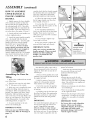
ASSEMBLY
HOW
(continued)
TO ASSEMBLE
UPPER
HANDLES
PIASTIC
visually check that the throttle triangle
hits both the idle screw and the full
open swp, THIS MUST BE DONE
BEFORE S'IT*_RTINGTHE ENGINE.
&
CARR_ING
HANDLE.
i, Lightly squeeze the lower handles
(#3) toward one another so that they
line up with the two smaller holes on
the carrying handle (#29). Then slide
the carrying handle over and down the
lower handles. It will rest about four to
six inches
above the engine
(Picture
2. Gently pull the lower handles
to their original position
1)
out
3. Attach the upper handle assembly
(#I) - the handle with the throttle
cable and ground wire - onto the right
handle, and secure with the handle
knob (#40) and 1 J_und head bolt
(#39) (Picture 2). Be sure you have
proper throttle
movements
and that
the throttle cable is not wrapped or
twisted around
the handle bar.
Squeeze trigger and let go. The triangle
must click in both directions.
If there
is any doubt, remove air :filter and
4. Follow the same steps to install
the left upper handle onto the other
lower handle. (Picture 3)
Picture
1
Picture
2
Picture
3
Picture
4
5. Use the clip (#6) to secure the
throttle cable and wire in place on the
lower handle. (Picture 4)
6. Now install the Handle Brace.
Line it up with the holes on the upper
handles. Then insert a Cap Screw
(#34) and a Lock Nut (#35) on either
side (Picture 5)
7, Use a w_mch to tighten Cap
Screws and Lock Nuts.
8, Now use wrench to tighten all
nuts and bolts firmly and securely.
IM[PORTANT
A
WARNING:
NOTE:
Improper thro_ie
installation can
cause tines to
Make sure you have installed
the
handles
properly: When yon stand
behind your tiller, holding the
handles, you should face the
gasoline
tank.
rotate unexpectedly.
Pictm_e5
Assembling
the
Tines
for
Tilling
1. Remove the cardboard
your "riller's base.
from around
2. Slide the tines onto the axle shafts.
The "D" hole goes on the outside.
3 Make sure you've installed the trees
properly for tilling. Liken the tines to
your fingers. When your pahn. t_ces the
ground, your fingers curl down. Stand
behind the Tiller and hold your hand
next to the tines. Do the tine blades curl
down, as your fingers do? If so, th W are
in tire tilling position. ('Ib switch to the
cuhivaOng position, see pagy_ 10.)
4. _lb secure each tine to the axle,
insert a tine retaining pin.
IMPORTANT
NOTE:
Belore you use your MANTIS Tiller,
read the Safe D, Rules & Warnings on
pages 3-4.
6
Your MANTIS Tiller comes with a
Dee pre_measured bottle of two<ycle
engine oil. Here's how to mix the oil
with the gas:
proper t;ael mixture.
I.Pour 1/2 of the gasoline into a sate,
container. Do not mix the fuel and oil in
the engine fuel tank.
Remember
2. Add 2.6 ounces of two-cycle
engine oil to the gasoline and mix.
Then add the rest of the gasoline.
3. Screw the cap onto the gasoline
can. Then swirl the can to blend the
oil and gas.
4 Carehtlly pour the fuel mix into
the tiller_s fuel tank. After putting the
fuel tank_ cap back on, wipe up any
spilled fuel from tank and gasoline
cal2.
Need more pre-nreasured engine oil?
You can order it from your local
authorized MANTIS dealer.
.,,
*Always :nix two-cycle oil with
gasoline betore fueling your tiller.
Neveg ever run your tiller on gasoline
alone. This will ruin your engine and
void all warranties.
•Always use a clean gas can and always
use unleaded gas.
• Never try to mix the oil and gasoline
in the engine fuel tank_
•Always mix oil and gas in the proper
proportions: 26 ounces of two<ycle
engine oil to one gallon of unleaded
gasoline.
IMPORTANT:
IMPORTANT
Fwo stroke tiael separates and ages. Do
not mix more than you wit/use in a
month. Using old fuel can cause
difficult starting or engine damage°
Shake fuel container
to thoroughly
mix
fuel before each use. Do not attempt to
run your engine on gasoline only, use
Do Not use old or stale oil/gasoline
mixture.
Always use the proper
oil/gasoline
m_ture.
If you do not,
your en#ne will suffer rapid,
permanent
damage. And you _1l
void the engine warramy.
NOTE:
ASSEMBLY
(continued)
M ng
Fuel
Your MANTIS Tiller is powered by a
commercial two stroke, air cooled engine
which requires a luel mixture of gasoline
and lubricating oil.
Use a mixture of 50 par_s unleaded
regular gasoline and I part two-stroke
MANTIS oil (50:1.) Use branded 89 octanc
(R÷M+2) unleaded gasoline or gasobol
(maxmmm 10% ethyl alcohol, or 15% MTBE, no methyl alcohol.)
STARTING
To Start
First
Your
Tiller for the
Time:
1_ Fill the luel tank with the proper
oib"g/asoline mixture°
(See previous section.)
2. Hand tighten the gasoline cap just
until it_ snug_
3. Place the O/I switch into the
"start!on" position (Picture 1)
starting. Press the purge bulb until
you see fuel flow through the clear fuei
return line. Since you're starting
"cold," you may need to press six to
eight times. As soon as fuel starts
flowing through the clear fuel line, stop
pressing! (Picture 3)
five times. Ovewulling
may cause
flooding. Also, bear in mind that, when
the engine fires, it only coughs or
sputter,
and will not run on choke.
6. Don't press the throttle trigger
during the starting of the engi_e.
9. Then pull the starmr cord again°
The engine should start and run. Let the
engine warm up two to three minutes
before using.
7. Pull the starter cord (Picture 4)
until resistance is t)tlt. Then give the
recoil starter coMa few brisk pulls until
the engine fires, Note: Pull the starter
cord about 12 '' to 18". During cold starting, you may need to pull at least three or
four times belbre the engine fires.
4. Pull the choke button all the way
out, to completely close the choke
(Picmre 2)
5. Locate the purge bulb on the
upper right of the engine, in front of
the fuel tank. (See Picture 3) It sends
fuel into the carburetoL for easy
NOTE: When the choke is closed,
never pull the cord more than four or
8. Push the choke button in, all the
wag to open the choke. (Picture 5)
Follow these stqos whenever you are
starting the engine "cold", or when the
engine has run dry and you have .just
added fiM, Remember, always _se short,
b_isk pulls, DoM give the co_d a tong,
jbr_efuI yank, ArM, do not let the cord
snap bach into the start_
housing,
Never use starting
fluids as they will cause permanent
engine
damage. Using them will void the warranty.
Before you use the
tiller, read the Safety&
Warning
rules on pages 3_4.
Picture
3
Picture
i
Picture
2
Picture
4
Picmre
5
7
STARTING (co.ti.ued)
Additional
Information
How to Stop
the Engine
A Special
(with the idle set properly
and the en_ne running)
Simply push the oh
' stop/start"
switch to
'O" (Picture 3). This
will stop the engine
instantly. If it should
Picture 3
ever fail to do so, just
pull out the choke button. The engine
will stop at once.
About
Even when the engine is running,
the tines won't turn unless you press
the throttle lock out button and
squeeze the throttle lever on the
handlebars.
And, when you release
throttle lever, the tines will stop.
the Choke
The choke
controls
A Tip for
the amount
IN CASE
the filter back in the rank. Then follow
the normal starting procedure.
Here's Another
Way
Start
your MA_NTIS
I Push
Picture
•Remove the cap over the spark plug.
•Unscrew the spark plug. (Picture 2)
NOTE:
1
Picture
2
Picture
the switch
disconnect spark plug wire and
remove plug. Use a paper towd or a
dean rag to dry, the spark plug, then,
with the spark plug out of the engine,
pull the starter cord several times.
Next, replace the spark plug.
Use the wrench to tighten it and replace
the cap. Next, put the switch in the "|"
position and pull the choke button out.
Pull the starter cord three or four times
until the engine coughs or sputters.
Open the choke (push the choke button
in) and pull the cord a few times, the
engine should start and run.
2, If the end of the spark plug is dry;
check to see if the fuel liine is blocke&
First loosen the fuel cap to relieve the
pressure in the tank. The fuel line runs
from the fuel tank to the carburetor,
Pull it off at the carburetor end. Fuel
should drip slowly from the line Wipe
off any excess or spilled fuel.
flow of fuel to the engine. Just
2. Push in the choke button to open
the choke,
3. Press the plastic bubble
Engine
1. if the end of the spark plug is wet,
the engine may be flooded. Make sure
the switch is in the "0" position,
8
If fuel drips too freely, the line may be
disconnected from the fuel filter. >au'll
find the t;ael filter inside the fuel tank.
Just re-attach the line to the filter, and put
a few times.
4_ Give the starter cord a few short,
quick pulls_ The engine should start
and
run_
5. If the engine does not start, then
pull out the choke button to cIose the
choke. Pull the starter cord four to five
times. The engine should sputter or
cough.
6. Alter the engine sputters, push the
choke button in. Then pull the starter
cord The engine should start and run.
7_ If the engine still does not start,
repeat steps 2 through 6.
8. If the engine still does not start,
call your local authorized
I_NTIS
dealer.
IMPORTANT
NOTE:
Never u_ starting tluids° Starting fluids
will eau_ permanent
en_e
damage.
Using them will void the warranty.
IMPORTANT
a Flooded
to 'l".
3
If fiaeI does not drip from t/he line,
To avoid possible damage to the
threads, do not try" to remove the plug
from a hot alminum
Wlinder head.
Starting
to
Tiller
if you follow the steps above and
your engine still won't start, try this:
• First, examine the spark plug. Use the
special wrench that comes with our
optional MANTIS Handy Item Kit
(item #8444) or a 3/4 inch spark plug
wrench. (Picture 1)
IMPORTANT
Life
After you start the engine, let your
tiller warm up for two to three minutes
betore you use it. Then, before you put
TO DO JUST
If you follow the normal
starting procedure, you should
have no problem starting your
tiller. But, just in case you do
have problems, here's what to do.
Make sure the oh switch is on I
%tart." You'd be surprised how
many people forget to push the
switch into the 'T' position.
If the switch was on 'o" when
you pulled the cord, you may have
flooded the engine.
the
Extending
Your Engine's
of
air drawn into the engine. Your tiller
will run only if the choke is open -that is, if the choke is pushed in.
¥HAT
your tiller away; let it idle for a minute to
give the engine a chance to cool down.
Feature
NOTE:
Before yon use your MANTIS Tiller,
read the Safety Rules & Warnings
on
pages 3-4.
GETTING YOUR TILLER TO YOUR GAP EN
Walk
it.
Take
Once your tiller is running,
you can
"walk" i/to your garden. Just press the
throttle lock out button and squeeze
the throttle lever gently and let the
tiller "tipotoe" across your yard on its
tines. It won't hurt your lawn or
Car_
It for a _de.
You can easily transport your
MANTIS Tiller to a [fiend's or relative's
house Just empty the f_ael tank_ (This
is crucial.)
Then stow your Tiller in
the trunk of your car or truck. It fits
easily. And you can put it in and take it
out without straining your back.
It.
Make sure the engine is off. Then
use one hand to grasp the convenient
carrying handle. Use the other hand to
hold the handlebars.
(Picture 1) Then
lift your tiller and car D , it to your
garden. Since it weighs only 20
pounds, it won't strain your muscles or
tire you out!
Picture
I
Picture
2
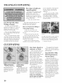
TILLING
Now You're Rea@
MANTIS Tiller.
to Use Your
if you've seen other tillers, your MANTIS
Tiller may surprise you. It tills best when
you pull it backward! You see, when you
pull your MANTIS Tiller backward, you
give extra resistance to the tines, so they dig
deeper. (Picture 1)
Picture
1
Whatg more when you go backward, you
erase your footprints. So your soil stays
light and f/uf[}_.With other tillers, by
contrast, you walk right over the soil you've
just tilled, packing it down, so it's less
plantable,
Run Your MANTIS
a Vacuum Cleaner.
Picture
2
Tiller
like
Place your Tiller at the head of the row
or area you want to till. Start it up. Then
use an easy rocMng motion. First, pull your
Tiller backward Then use an easy rocking
motion. Again, pull your J?ller backward.
Then, let it move forward just a little bit.
Then pull it backward again. This witl help
you till deeper_
Keep repeating these steps until you've
tilled an entire row. Start again on the next
row. It_ much like running a vacuum
cleaner! (Picture 2)
Picture
You Can
Even
For Deeper
Tilling:
Control
Depth.
Move your Tiller slowly back and k)rth,
as you would a vacuum cleaner. Work the
same area over and over until you've dug to
your desired depth. (Picture 3)
For Shallow
Tilling:
Switch the tines to the cultivating
position.
(See page 10 to learn how.) Then
move your Tiller quickly over your soil
surface.
For Big Weeds or Tough Roots:
Let your Tiller rock back and torth over
the tough spot, until the tines slice
through the weed or root.
Your NL&NTIS Tiller Handles
Special T_ng
Projects.
Want to mrn part of your lawn into a
colorful flower border? "four MANTIS Tiller
makes it easy! Just run your Tiller back and
forth until the sod begins to break up Then
continue tilling. Your Tiller will chop the
clumps of sod until they're line. Then, it
,#ill work them into fbe soil. Pretty soon,
you'll have a soft, fresh planting bed.
3
9
How about a family-size
vegetable garden?
tractor or big tiller to break ground
for you. This is a one-time-only
investment that's well worth the
small cost.
Nowadays many gardeners prefer
small gardens -- especially in the
suburbs, where space is at a
premium. But, if you're t0rtunate
enough to own a large lot, you can
create a bigger garden -- a half acre
or more. Here's how:
2. Then, use your _filler to break
up any remaining clumps of soil or
sod. Unlike a tractor or big tiller,
your MANTIS Tiller is a precision
tool. It will pulverize your soil into a
smooth seed bed.
1. First,. hire someone with a
"Your MANTIS
Weeding
Tiller Makes
a Pleasure!
As a tiller, your MANTIS Tiller
works the soil down to 10" (25.4 ca)
deep. But, as a cultivator, it gently
cultivates the sur[ace, only 2" to 3"
(509 cm to 7.62 cm) deep.
The result? Your Tiller will cut your
weeding time in half, and turn a
tiresome chore into a pleasure
How
to Switch
Cultivating
From
Tilling
to
Position
1. Make sure your Tiller is off.
First, you must change the tines to
the weeding position. This takes less
than a minute.
2. Ren-tove the retaining pins from
the tines.
Then, your MANTIS Tillerg sharp
"tine teeth" will slice up those pesky,
weeds, burying them as you go along.
And, since the tines in this position
won't dig too deep, they won't hurt
your plants' precious root systems.
4. Place the right-side tine onto the
left-side axle. Place the left side tine
onto the right-side axle. The "D" hole
should be to the outside.
3 Remove the tines [rom the axle
5. Here is how to make sure you've
installed the tines properb: Sand behind
Picture
1
Picture
2
the Tiller and hold your hand, pahn up,
next to the tines. Do the tine points
curl up, as your fingers do? if so, they
are in the correct cultivating
position.
6. Reinsert
the pins.
CULTIVATING
Now You're Ready to
Cultivate
or Weed.
Guide your Tiller where you
want to weed and start it up.
Pull your Tiller backward
slowly_ then let i_ move [orward
a biL in a gentle rocking
motion. "Watch it slice, shred,
and bury those weeds!
Tilling
Position
Tine teeth point in the
same direction as the
rotation of the tin< or
toward the [ront of the
Tiller, away from the
operator,
10
Cultivating
Position
Tine teeth point in the
opposite direction as the
rotation of the tine. Tines
point toward the back of
the tiller, or toward the
operator.
Got tough weeds? Lighten
yore" pressure on the throttle to
slow your Tiller down. Then
work back and forth until your
Tiller chops up the weeds, it's
easy and eltective!
Remember, any tiller will
tangle in tall grass_ stringy
vines, or supe>bg weeds, So, ff
you have a "backyard jungle,"
first use a knife, pruner, or
brush cutter to chop up the
ove>growth, If the tines become
tangled anywa> push the
switch to the "o" position to
turn the engine off complele|y
be[ore trying to clear them.
The optional Tine Detangler
(Item #1322) will clear tines in
a jifl_. Call your local authorized
MANTIS dealer,
Your M&NTIS
"Will Weed
Narrow
Tiller
Between
Rows!
Your MANTIS Tiller is a
precision weeder that easily fits m
tiOxt places. So don't be afraid to
weed awwhere: between plan_
and shrubs; in corners; against
[ences; on raised beds; in wide
rows; even in very narrow rows.
_Amr MANTIS Tiller weeds six*
to nme inches wide. So you can
run it in a tightly planted garden
without damaging your delicate
plants. That's good news for
suburban gardeners, who often
have to plant rows dose together!
*V,/ith optional Planter
Furrower attachment
(Item #6222.)
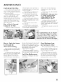
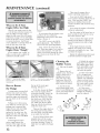
MAINTENANCE
Check the Air Filter Often
A wet or dirty air fiher can affect the
way your engine starts, performs, and
wears, So, it's a good idea to check }*our
air filter once a month.
If you work in dust}, soil, or if you
want to be on the saff_ side -- then
check your filter more often (for
instance, betore each use). But be sure
to replace it at least once a year, in the
spring or/all. Clean or change it as
needed. It is recommended
to change
the air filter yearly
How to Check,
Change
Clean
of the ai>cleaner cover, (See Picture 1,
or took up Key #1 in Air Cleaner Parts
Assembly on page 17,)
2. Take off the cover. Make sure to
clear the choke button. (Picture 2)
Order a new one directly fi'om our
Customer Service Dept. CalI 1-800366_6268o
3, The air filter is the pad on the
inside of the ai>cleaner cover. Check
whether it is soiled or moist
IMPORTANT!
blake
sure filter
is "seated"
properly
in the
cover. The filter must fit
snugly
inside
the rim that
holi[s the filter in place.
7 Insert your clean filter inside the
ai>cleaner cover.
4. If the air filter needs cleaning or
no longer fits properly; remove it. Just
lift an edge careRdly and 'peel" it out
(Picture 3)
installing the filter incorrectly will
cause engine damage and void the
warrant): Fit the cover back over the air
cleaner. (Again, make sure to clear the
choke buttom)
5. Use a brush to remove debris
fl'om the pa&
and
6. If the air filter is so dirty" that it
won't come clean, you m.ust replace it
or severe eng:ine damage will occur.
the Air Filter
1. Loosen the wing nut on _he side
8. Tighten the wing nut to secure the
cover.
Note:
Picture [
How
Picture 2
to Check
the
Worm
Housing
Gear
check
the lip on the Air Cleaner
Cover.
If the
lip is chipped
it should
be replaced.
dirt from
being
carburetor
into
ingested
the
or cracked,
This
Mll
prevent
through
inside
of the
the
engine.
Picture 3
the Grease
Level Inside
Please
the top of the housing_ If it doesn't, add
lithium #0 grease (Item 9985.) This is
the only- way to add grease to the worm
gear housin& (Picture 2) 'lb purchase
MANTIS grease, call your local
authorized
MANTIS dealer.
When we buih your MANI1S Tiller
we lubricated the worm gear housing
thoroughly
After you've used your Tiller [br a few
seasons_ check [or blockages in the fuel
tank and fuel filter. Such blockages can
keep your ?filler from stardngo
Please do not overfill. Too much
grease can create pressure, which could
cause seals to fail or the clutch to slip.
It is imperative
that you inspect the
grease level once a year: Simply remove
the cover plate on the worm gear
housing. (Picture I) Then check to
make sure the grease comes almost to
Picture
Clear Blockages
From
the Fuel Line & Filter:
Fuel
Filter
Clear any blockages you see in the
tank, fuel filter, or fuel line. Remember:
The fuel filter is located inside the tank.
Replacement:
(See Picture
Fuel filter to be changed at the end of
every season,
starting
3) Then use the normal
procedure
to start your Tiller.
2
Picture
3
Picture: 1
11
MAINTENANCE
(continued)
Then stop the engine after it
reaches operating ternperamre.
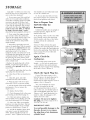
What
Engine
Now, turn the RED, high-speed
screw counter-clockwise all the way to
stop. °Then turn the WHITE, low
speed screw hali\vay between the
counter-clockwise and clockwise stop
positions.
to Do ff Your
Idles
Too High
What it your engine runs too last
.. or if the tines turn the instant you
start the Tiller? "x_9umay need to
adjust the idle screw (Key #19 under
Carburetor on page 17) by itself right
below the H and L screws. Gently turn
it counter-clockwise. _bu'll know
you've adjusted it correctly when the
axles do not turn at low idle.
V_rhat to Do ff Your
Engine
Runs
"Rough"
If your engine runs "rough" or
stalls, you may need to adjust the
carburetor and idle screws.
Picture
Now restart the engine to finish the
carburetor adjustment.
I
If you remove the air-cleaner coveL
you'll see the two carburetor,
adjustment
screws next to the choke
button. (Picture 1)
The "RED" screw is the HIGHspeed adjustment..The
"WHITE"
screw is the low speed adjustment.
First, remove the tines from the
axle_ Then start engine. Let it run for
two to three minutes.
"F:LASH" the
choke several times during the warmup to clear any air from the Fuel
system.
Run the engine at full speed two or
three seconds to clear out any excess
fiael. Then return to idle.
Now, accelerate the engine to flail
throttle several times to check for a
smooth transition from idle to high
speed.
If the engine hesitates turn the
WI!ITE, low-speed screw counte>
clockwise one<ighth of a turn. Then
accelerate the engine.
Repeat the adjustrnent until you get
a smooth transition to high speed.
Cleaning
the
Muffler Screen
1. Take out the spark
plug
Picture I ,., Note how the engine
doesn't sit all the way down on the
transmissions.
Ho'w
tO Reseai
the Flange
At some point, you may find
that the tines won't turn when
you press the throttle. This may
mean the engine isn't sitting all
the way dov,m on the worm gear
housing.
Perhaps you've been using
your Tiller for several years. Or
perhaps you've removed the
engine for use with our hedge
trimmer attachment, then
replaced it. In either case, the
flange bolt (Key #38, page 18)
may have come loose and lifted
the engine up.
If this happened
you'll
notice a gap between the
bottom of the engine clutch
case (Key #37, page 18) and
12
Picture 2 ,.. Note how the engine
the way down on the transmission.
sits all
the top of the worm gear
housing. (Picture 1)
To fix t_his,loosen the flange
bolt. Take the engine off the
worm gear housing. Notice tl:le
hex head on top of the drive
shaft (Key #9, Page 16). Inside
the clutch case, you'H find the
clutch drum (Key #31, Page
29). Make sure the hex head
lines up with the clutch drurn
inside the clutch case.
Then put the engine back on
the worm gear housing. Make
sure the plastic carrying handle
is not under the fuel tank.
If you've [bHowed these steps
properly, there will be no gap
between the clutch case and the
worm gear housing. (Picture 2)
Make sure you tighten the flange
bolt!
2. Remove the red
cylinder covet (Key #32)
which is held on by 2
phillips-head screws,
(Key #33) and 1 hexhead screw, (Key #34)
which you will need an
allen wrench to remove.
3. _fbuwilt see the
metal exhaust guide, held
on by 3 more phflfips-head
screws. (Key #26) Remove
the exhaust guide.
4. Behind the exhaust
guide (Key #25) will be
the muffler gasket (Key
#24) and muffler screen
(Key #23), The screen
sits under the gasket.
5. If the screen (Key
#23) is clogged with
deposits, it needs to be
cleaned. Use carburetor
cleaner, and any brush
that is not metal Brush
the screen until you are
able to see through it.
6. if the screen
remains plugged after
attempts at cleaning, it
must be replaced.
Each/illl-- orbefore
youstoreyour
MANTIS
Tillertbranylongperiod-- be
suretotakethese measures:
1. Do not store your l?ller with fuel
still in it. Even under ideal conditions,
stored fuel containing
ethanol or MEBE
can start to go stale in 30 days. And,
since stale fuel has a hNh gum content,
it can clog the carburetor,
this, in turn,
will restrict fuel flow. So, when yon're
read}, to store your Tiller, or NIl not
be using it for more than 2 weeks,
drain the furl tank completely
(Picture 2)
2. Next, restart the engine to make
sure no fuel is left in the carburetor:
Then run the engine until it stops. This
will prevent gum deposits, forming
inside of the carburetor
and possible
engine damage.
3. Disconnect
spark plug wire and
remove the spark plug. (Use the wrench
that comes in our optional
Handy item
Kit, Item #8444. Or use a 19ram or 3/4"
spark-plug
wrench.) Pour about a
teaspoon of clean, at>cooled,
two-cycle
oil through
the spark-plug
hole into the
combustion chamber. (Picture 3) Leaving
the spark plug out slowly pull the starter
cord two or three times to coat the inside
of the cylinder +wall+
4. Replace the spark plug with a NGKBPMSY. A repIacement
spark plug is
included in the optional
Handy Item Kit
item # 8444.
5 Install the spark plug, but leave the
spark plug wire disconnected.
6. Clean the air fiher as described
Page 11.
on
7. Clean dirt, grass, and other
materials t?om the entire machine.
8. Wipe the tines with oil or spray
them with WD-40, to prevent rusting,
9. Oil the throttle cable and all -,qsible
moving parts (Do not remove the
engine cover.)
10. Replace the fuel filter.
1I. Check the grease level in the worm
gear housing, as described on page 11,
Your handles are now folded and ready
to store in a smaller area,
15. Do you have fuel left over from
last season? Dispose of it properly_ Buy
fresh oil and gasoline next season.
How
to Prepare
MANTIS
Your
Tiller
for
Restarting
Unfold _he handles into an upright
extended
position. Tighten the two
handle knobs (#40)
In the Spring, when you take your Tiller
out of storage, remove the spark plug.
Pull the star_er cord three or four times
to clean oil from the combustion
chamber
(Picture 4) Wipe oil from the spark
plug. Place the spark plug back into the
cylinder, Re-connect the spark plug wire
back on the spark plug. Then lollow the
steps on pages 9 & 10 to ret:uel and
restart your Tiller.
Again, Check
Carburetor.
if your Tiller won't restart in the
Spring -- or if it lacks its usual power
-- the carburetor
may need attention.
Follow the steps on page 19 for adjusting
the H and L screws. (Picture 5)
Check
Picture
i
the
the Spark
Picture
Picture 3
2
PLug Too.
If your 'Filler won't restart, or if it
lacks full power, the spark plug may be
at fault. Check to see if the plug is
fkmled with oil.,/black deposits. Clean or
replace it if it is. (Picture 6)
Also, check whether the center
electrode is rounded at the end,
Picture
4
or if the ground electrode is worn. If
either is the case, you should replace it
with a NGK_BPM8Y spark plug. Use a
19rmn or a 3/4" spark-plug
wrench to
install it. Adjust the plug gap to .024
12. Order new parts to replace any
that are badly worn or broken, Just coil
your local authorized MANTIS dealer.
,028 in. (0.6 to 0.7 ram)
13. Store your Tiller, in an upright
position, in a clean, dry place, "_bucan
store with the handles in an extended
position or folded down. (Picture 1)
22 ft.-lbs.
14. "Ib fold the handles, tbllow these
easy steps: Loosen the handle knobs
(#40), fold the handles forward (see
picture 1, inset). Tighten knob securel>
or
Caution:
the plug.
Do not
over
The correct
(24-30 n.m)
IMPORTANT
ti_titen
torque
is 18 to
P_cture 5
Picture
6
NOTE:
To avoid
threads,
the plug
possible
damage
to the
do not try to remove
from a hot aluminum
cylinder
head.
13
TROUBLE
SHOOTING
Problem
1° Tines don't turn when throttle
is depressed
Cause
Remedy-
+ Engine is not seated properly on the gear
+ Re+instaI1 engine following the instructions
on page I2 (How to reseat the _Tange).
2. Engine fails to start
O11switch is in +o" position,
*
+
*
,
*
No fuel in tank.
Fuel strainer clogged.
Fuel line clogged.
Spark plug shorted or fouled+
Spark plug is broken (cracked
porcelain or electrodes broken)
, ignition lead wire shorted, broken or
disconnected from spark plug.
* Ignition inoperative
3_ Engine
4. Engine
hard to start.
continuously
*
floods.
'&'ater in gasoline
o
Move switch to _+12+
Q
Fill Tank.
Replace Strainer.
Clean fuel line
Install new spark plug.
Replace spark plug.
o
o
Replace lead wire or attach to spark plug
Contact your local authorized
or stale fiael mixture.
Drain entire
fresh fuel.
system
dealer+
and refill with
+ lbo much oil i_ iuel mixture+
Drair_ and refill with correct
*
Engine under or over choked
*
-
Carbm,:tor
out of adjustmenL
Gasket leaks (carburetor
or cylinder
base gaske0+
Weak spark at spark plug.
If flooded by over choking, proceed
according to instructions iu operation+
section, If under choked, move choke
lever to dosed position m_d crank two or
three times.
See "Carbtxretor Adjustment'
Replace gaskets.
Contact
your
local authorized
mixture.
dealer+
Return the t:uel tank vent line to the
upright: position and place it under the
cyiinder cover in the small pocket" in
the cylinder cover
+ Fuel tank vent line is not in an
upright position.
5+ There is black smoke coming from
exhaust
* The muffler screen is clogged
* Clean carbon frorn mufIler screen (page 12)
6. Engine misses.
* Dirt in tuel line or carburetor.
+ Carburetor improperly adjusted+
* Spark plug fouled, broken or incorrect
gap setting_
* Weak or intermittent spark at spark plug.
+ Remove and clean.
* See '_Carburetor Adjustment2
* Clean or replace spark plug - set gap to
024-.028 in. (06-0.7 mm)
- Comact your local authorized dealer.
7+ Engine lacks power
*
,
+
+
Air filter clogged
Carburetor out of adjusnrmnt+
Muffler clogged
Clogged exhaust ports.
+ Spark Arrestor Clogged.
* Poor compression.
8+ Engine overheats.
+ Insut_icient oiI in fuel mixture
+ Air flow obstructed
Clean or replace air filter.
See "Carburetor A_ustment"
Clean carbon from muNer+
Remove muff lee rotate engine until the
piston is at top of cylinder. With a
wooden scraper or blunt tool. remove all
carbon from exhaust ports. Be carefu! not
to scratch or damage piston or cylinder
wails+ Blow out all loose ca_on with
compressed air+ Install muffler and gasket.
+ Clean Spark Arrestor
Contact your local authorized dealer.
o
+ Mix fueI as described iu slarting
instructions.
+ Clean flywheel cylinder fins and screen.
91 Engine noisy or knocking.
+ Spark plug in incorrect heat range.
* Beatings, piston ring or cylinder walls
are worn.
+ Replace x_ith plugs specified for engine.
+ Contact your local authorized dealer
i0. Engine stalls under load.
+ Carburetor adjustment mo 'leanY+
+
+ See 'Carburetor AdjustmentY
* Remove dust and dirt from between fi_s+
14
ENGINE
Dry Weight
I)pe
SPECIFICATIONS
.......
of Engine
2.8kg
....
-- 6 lbs., 3 ounces
Rotation .......
Bore ............
Air Cooled, Two stroke, Single-Cylinder,
Gasoline Engine
Clockwise,
viewed from TOP
32.2 mnr (1,268 in.)
Stroke
26.0 mm (1.04 in)
..........
Spark Plug ........
Fuel ...........
NGK BPMSY
Premixed
two stroke
Fuel Oil Ratio
50:1 ratio with MANTIS
Gasoline
.....
.........
Unleaded
SER CE
fuel
oil
Displacement
.....
Exhaust System ....
Carburetor .........
Ignition System ....
21.2 cc (1.294 cu. in,)
Spark arrester muffler
ZAMA diaphragm model C1U type
Flywheel magneto, capacitor discharge
ignition type
Starter ...........
Automatic rewind type
Oil ............
Designated, two-stroke, ai>cooled
engine oil
FueI Tank Capacity .0.5 lit. (17.0 oz)
(see page 7)
MAINTENANCE
GUIDE
Area
Maintenance
Frequency
Air Filter
Clean
Replace
Daily or every 4 hrs use
Every 3 mths. or 90 hrs. use
Fuel Filter
Inspect
Replace
Mor_th|y
Spark Plug
Clean
Replace
Every 3 mtbs. or 90 hrs_ use
6 months or 270 hrs. use
Carburetor
Check / Rebuild
Replace
6 months or 300 hrs. use
Yearly or 600 brs. use*
Cylinder Exhaust Port
Every 3 mths. or 90 hrs. use
luspect / Clean
Betore Use
Inspect / Clean
Monthly
Gear }lousing
Check Grease
Yearly
Trees
Inspect / Clean / Lubricate
After Use
Fuel Leaks
Inspect / Repair
Betore Use
Fasteners
Inspect / Tighten / Replace
Bet}:_reUse
Labels
Befure Use
Handles
Behare Use
Guards / Safety Devices
Inspect / Replace
Before Use
Fuel Line
Inspect / Replace
Monthly
Starter Rope
Monthly
Fuel Strainer
Replace
EveW 3 mths. or t00 hrs. use
Choke
Check
With each reo_t_aeling
Ignition .System
Clean
Replace
No maintenance
For coil and flywheel
Replacement w_tlbe required for commerdal use aher 600 hours. For CoT_sumeruse, cleaning every 6 months is required. Cleaning i_c[udes Rebuild Kils.
IMPORTANT:
Time Intervals
shown are rnaxinmm.
Actual use and your experience
will determine
the frequency
of required
maintenance.
Notes:
15
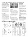
USING
THE BORDER
EDGER
ATTACHMENT
Your MANTIS Tiller has been
designed and built to accept a -,vide
range of MANTIS Tiller Attachments to
increase its usehalness in your lawn and
garden. And, all MANTIS Tiller Attachrrtents have been designed/br quick and
easy attachment to the Tiller or Engine.
How
Border
(Item #3222)
Picture
The most popular attachment, the
Border Edger can be used to create
clean, neat edges along walkways, or
around trees, shrubs, and garden beds.
2. Then slide the Edgerg wheel onto
the right axle,
1
Picture
The Border Edger has two parts: a
Wheel and a hardened steel blade, with
pointed tines.
How
4. Insert retaining pins on both le[t
and right axles.
Border
Edger
The foliowing instructions refer to
'right" and ' left" axles. Assume that
you're standing behind your Tillec as
you would for tilling and cultivating.
Some areas of your yard may harbor
roots and other underground
obstructions. In places like this you'll
want to edge your borders shallowly
(1" to 2" deep). Here's how to install
the Border Edger tor shallow edging:
I. First remove your tilling,,'
cultivating tines.
MANTIS
TILLER
2. Start your Tiller and pull your
MANTIS backward along the garden
edge. (Picture 2)
2
3. Now slide the Edger blade onto
the left axle. The blade's angled face
should bit the ground when you spin
the blade forward; do not operate tiller
without tine pins in place
the
E@r
i. Position your MANTIS Tiller so
that the Edger blade is right along (he
garden edge and the wheel is outside
(on the lawn, on the sidewalk,
wherever). (Picture I)
The Border Edger
to Install
to Use the
The Border
Handle
Special
Can
Projects!
1. Install the Edger lor deep edging,
as directed above. Then use it to cut
sod strips.
2. Edge and weed at the same time!
Just attach the Edger blade on one axle
and a Tiller fine on the other axle, "Mix
and match" blades; don't be afraid to
experiment.
Around walkways and garden beds,
you'll want to edge more deeply (3" to
4" deep). Here_ how to install the
Border Edger for that purpose:
1. Remove the tilling/cultivating
tines.
IMPORTANT
NOTE:
If you do a lot of edging, you'll
appredate
the Mk_NTIS Wheel Set
(Ire:m#9222.) It gives you added
stability, for even easier handling.
2 Slide the Edger_ blade onto the
right axle The bladeE pointed face
should hit the ground when you spin
the blade forward; do not operate tiller
without tine pins in place
3 Slide the wheel onto the left axle.
4. Insert retaining
Edger
_lborder the Wheel Set or any
MANTIS Attachment, call your local
authorized MANTIS dealen
pins on both sides.
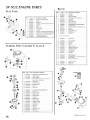
ASSEMBLY
P/N 438LA
P/N 438RA
DIRECTION
D_RECTION
Raised
Hub
Teeth point
a Clockwise
Direction
Hub
in
....
When _o_1 look a a [me wiIh the aised
|TEI_NAME _q.TY
NAT_81AL
1 400254 1 Trigger Handle
Assm, RH
2 400255 I HandleAssm, LH
3 400224 2 Lower Handle Foid Down
4 400620 1 Label
5 148
1 Handle Brace
6
7
478
465
8
400908 !
*9 468
10 466
16
2 TbrotBe Ciip
1 Fender Guard
EngineAssm, SVo
5C/2
1 Drive Shaft
! Worm Gear
11 436
12 437A
13 651
Ho_sing
1 Gasket
1 Housing Cover
4 Rd Hd, Se#
14 423
Tapping Screw
1 Roller Bearing
tmb [amg
When yo_ i_ok at "Ine ,vdl de raised hub facing you
a_d the _eeth are poi_Im_g in a (OUNIER
Cn)CKW1S[:
_n_adm, ym_ a_ad a RIG[IT ;CIANI}MINE
ITIENNAME QTY MATernAL
!5 425
2 Worm Bearing
Race
16 424
!
17
18
19
20
2!
22
I
I
1
!
1
2
422
426
428
429
431
430
23 432
24 434
25 435
point in
a Counter C!ock_
wee Direction
Worm Thrust
Bearing
Worm Shaft
Worm Disk
Retaining Ring
Worm Gear
Tine Shaft
Worm Gear
Thrust Washer
2 Worm Gear
2
2
26 438RA I
27 438LA I
28 418-1 2
Bearing
Beark/g Seal
Bearing Sea!
Retainer
Ene Assm, (RT)
Tine Assm (LT)
Fine Retaining
Hair Pin
ITeMNA_E Q_
29 400218 1
30 487MA 1
31 4043
1
NATEmA[
Carrying Handle
Engine Label
Tine Label
32 458
33 4058
1 Relier Bearing
1 Mantis LabeI
34 410
2 Cap Screw 1/420 x 1" LG
4 Lock Nut 1/4 - 20
2 1/4 - 20 x 3" Bolt
2 Bolt 1/4-20 x
3/8" kg.
2 HandIe Ctamp
2 Bolt
2 Knob
2 Plug
1 Transmission
Assm.
35 972
36 470
37 140
38
39
40
41
42
377
400509
400510
400230
400010
* Also in Key #42
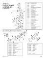
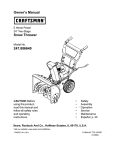
ITEM
SV-5C/2
ENGINE E4RTS
ASSEMBLIES
B _;t51_]€_20
_
Nl: ']AINI_{, PURGE PUMP
4
I_X}51_;_NSI]
1
BASE PURGE
----,,-
/
-
:
6
12533942¢_30
1
SCREW METERING LEVER P_N
8
_2537242B30
1
SWWEL
111
NI:_;1_3107_1
I
SItAFL TNR(YFrLE
2
125314139311
SCREW, THRUI_rLE VALVE
I4
1253_715_30
CLI_VrHROTrL_
SIL'_
CA_URETOR
@
QTV, DESCRIPTION_S
2
5
@
PART
#
I6
_25_2909a@
EAP, MIX'_URE LtMI EER- LOW SPE_iD
_25"{_)!a31g
NEEDLE
8
/253293903#
CAE M[XI URE L/MFIER - HIGH SPEED
22
125319i282t1
23
1253 _413 20
25
27
.................
2
[tl!Gff S_EgD
SCPd_W H)EL PUMP COVER
REIS\!R KIT / INCI,{ DES t_IEMS 24-3
I
GASKE'E METt RING DIAPHRAGM
1
_VN{
ME_INNNG
v_a::v
E,lal ,_'_NBDEE
2¢
3/I
I
__._.ss____=..__
3]
.........................
3
.....................
3g
/2._30313 2B
WELC_ Pi,_JG
STRAINER
1
GASKEZ F/[:L PUMP
I
GASKEZ;DIAPHRAGMKI_l{INCL1"DESI*ITiMS353g
;;; ; ; _ ;;;;;;
36
...........................
spin,o, MErVRNO1,Ev_a
DDNNRA(_M; MEJER!N()
I
GASKEZ METERING DIAPHraGM
, ;;,;,.22;.2:,;;2;2
38
AxR CL NER,
GASKET
MVFFLER,&
GASKET, fUEL PUMP
TnRorr E
KIT
ITEM
PART #
QTY
DESCRIPTION
/ REMARKS
I_M
2
13032611522
i
PART #
QTY. DESCRIPTION
/ REMARKS
COVEK A_R CLEANER
19
Aaiu_IIlI0S2t
1
NKFFLER
l
S(REEN,MLEFLER
4 lsos_c_4s(_t
_ _rEa, A_
23 14586240630
g
17851B00830
1
SEACER
17881005230
I
GROMMET
::9
10
i
BOLD Indicates New Pa_
..........................
12
AO211DIl_N
1
EARB/;RETOR
14
_._;_123805020
2
SCRE'@ 5X20
-- Ell-KS2
17
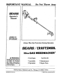
SV-5C/2 ENGINE PARTS
BLOCK
FUELTANK
2
A ER_)/_550
1
CYLINDER
vio_:_l_-a_i
l_
_,_r _ {,FY_
DEscmmoNREmRKS
2
_3R_528230
_
SPACER
4
V4711_i23{}
_
PIPE, FI_EI
P02_007712
6
10{R)1311520
t
PIN, PISTON
10{5_314i
152(}
2
SPACER, P_S'ION PIS;
V55300(_)10
t
BEi'_RING ,NEED_ E
1002_242031
2
OIL SEAL
i_i_:_x._)N
8
3X5X2 0MM/BtlKOgI']ON:9(}{}i4
7 ._z05ov_:o _ PILre_<FU_L
12
_
_i _N ......
130H I00530
l
CLIR PIPE
11
13201t}49030
_
NPE, RIJlUR)-a _3X_XS(P_IM/ BULK ON?ION: 9{_11
*
i
I4
I(_F2_242031}
t
GASKET, CRANKCASE
/6
90016205028
3
BOI_ 5X28
GASKE'L 115EL'IANK ( AP
Also i_chld_t iI_GASKET KIT
i7
PI}2it}091 iI)
l
GASKE!i KIT
l_ A4iiiu_:i_aii
COIL;
iiiSi;ri0r;
20
1
BUSHING
i56! I_14920
v4v_c_
STARTER,
PAWL
CATCHER
&
CLUTCH
18
PART #
QTY. DESCRII:_rION
17722605530
1
ROPE
15901N)1620
t
CAP, SI_RK
X t0(_gMM 39q/2
PIUG
24
I59¢_I019830
t
SPARK PlUG - BPM_Y
26
6t032502730
1
WOODRU/P
29
1772021222{}
1
S'_ARIER RAWLAS_x / INCLUDES [TfMS 3031
3]
177234t2220
2
SPRIN& PAWL R]2"IURN
32
A16(_1()0611}
t
COVER_ CYLINDER
2
SCREW
4X8
KEY
GASKET
/ REMARKS
STARI'ER 3MM(1/8'
...................
22
2_4 9I_/l?o_/o_
ITEM
................
i_v_50b_o
9
_
PIS_ON, KIT / INCLUDES ITEMS 5o8
AOlil_m_a
tO
U_ 13101655830
t
......... ............
4
KIT
{
R ULK O}ff1ON: 999444400%
20
177228tlt20
22
11723644330
®-@
I
S_ARTERGRIPK1T
1
SCREW
a
25
17501(_)5020
]
bIU[_ CLUATH
N
2v i75oo_)5t3_
2 SHOE
CLUTCH
{
29
3_
9t)0_d._000010
1
WAS}tER/11
: 9_)0gf,)83@fX)
33
1750t4t1520
_
g
_aASI_ER,
CLUTCH
35
900238{_0f4
4
SCRIW4X]4
37
90060500(K)5
i
SPRING WASHER 5
1
CASE
38
39
5:N
6t022311520
CLUTCH
BOLD k_dicatesNew Pmt
18
EPA PHASE
2 / CALIFORNIA
TIER
YOUR
III EMISSION
RIGHTS
AND
CONTROL
WARRANTY
STATEMENT
OBLIGATIONS
The Elwironmental Protection Agency (EFLA)and the Cali[ornia Air Resources Board (C.A.R B_) and "rbe Equipment ManMi_cturer are pleased to explain the
emission control system warranty on your EPA Phase 2 / C.A.R B. "TierIII model year 2005 a_ul later small off road engine (SOREs). New small off road engines
must be designed, b_ilt and equipped to meet stringent EPA and C.A.R.B. anti--smog standards. Echo, incorporated must warrant the emission control system on
your small off road engine for the periods of time listed below provided there has been no abuse, neglect or improper maintenance o_ your small off r<)ad engi_le.
Your emission control ystem may include parts such as the carburetor
may be hoses, belts, connectors and other emissiomrelated
assemblies.
Where a warrantable
condition
MANUFACTURER'S
exists, the Manulacmrer
WARRANTY
WARRANTY
system, and the ignition system and catalytic converter
wiiI repair your small off road engine at no cost to you including
Also included
diagnosis, parts and labor
COVERAGE:
The 1995 and laier small off road engines are warranted
repaired or replaced by the Mannfacturer:
OWNER'S
or ItleI iqected
lk_r two years
If any emissionmelated
part on your engine is del;ec{ive, the part will be
RESPONSIBILITIES:
-As the small off road engine owner; you a_: responsible for the performance of the required maintenance listed in your Operator's Mamla[. The
Manufacturer recommends thai you reiain al! receipts covering maintenance cm your small off road engine, but the Manufacturer cannot deny warranty
solely [or the lack of receipts or for your tailure to ensure the performance of a!l scheduled maintenance.
-As the small off road engine ow'ner; you should however be aware that the Manu_'acturer may deny you warranty
a part has lailed due to abuse, neglect, imp_a)per maintenance or unapproved modifications.
You are responsible for presenting your small off road engine to the Manu{k_cturer's authorized
should be completed in a reasonable amount of time, not to exceed 30 days.
II you have any questions
regarding your warrant}' rights and responsibilities,
EPA PHASE
This is additional
WHAT
DOES
2 / CALIFORNIA
detailed information
THIS
WARRANFY
TIER
service center as soon as a problem exists.
you should contact your Product
III EMISSIONS
about the ED\ PitAS_g..2L.
coverage if your small off mad engine or
DEFECT
The warranty
repairs
Manufacturer.
"WARRANTY
°
_g.P_N.!o_[
EXPLANATION
[or your smali off road engine.
COVER?
The Manufacturer warrants tbat ym_r unit was designed, bnih and eq_ipped to coMbrm with applicable Calitornia emissions standards and that your unit is flee
from defecls in material and workmanship that would cause it to faiJ to cnMorm with applicable requirements within I_ve (5) years The wa_'ran_y period br@_s
on the date the product is delivered to a re_ail purchaser "this is your emission control system,
HOW
WILL
A COVERED
PART BE CORRECTED?
If there is a de{_'et in a part covered by this walranty; a Mamdacmrer
s Authorized Service Dealer will correct the deli, ct
You will _mt have to pay anything to have the part adjusted, repaired o_ replaced This includes any labor and diagnosis lot warrani:ed repairs performed
dealer, in addition, engine parts not expressly covered under this warranty but whose failure ix a _vsult qf a fhilut_: of acm, ered part will be warranted
Emissions
System repairs covered under this warranty
should be completed
in a reasonaMe
by the
time, not to exceed 30 days
IMPORTANT
!f the dfagnosi
reveals no delk_ct the emission
WHAT PARTS ARE COVERED
DEFECT
_NARP_a_NTY?
BY TttE
defect warranty
EPA PItASE
does not apply.
2/CALIFORNIA
TIER III 2005
& LATER
SMALL
OFF ROAD
ENGINE
EMISSIONS
,Any emission related part not scheduled to_; "required maintenance" (See Engine Operators Manual, %ERVICli MA1N'IENANCE SCHI!DULE ') wit! be
repaired or replaced witbin the warran V period. the repaired or reptaced part svill be warranted for the remaining Emissions Defect warramy period.
*Any emission related part scheduled for replacement during 'h_equired maintenance"
(See Engine Opermors Mammal, _SERVICE MMNTENANCE
SCHEDULE) is warranted for the period of time prior to the first scheduled replacement point for that part Any such part repaired or replaced under
warranty shall be warranted tPr the remainder of the period prior to the first scheduled replacement point/)_r tbat part.
°Any manulacmrer-app_wed
must be provided without
replacement part may be used in the perDarmance of any warranty
charge if the part is still under warranty:
,Any replacement part that is equivalem m pertk>rmance and dmabibty
warramy obligations o_;the mamd;acturer.
-'['he owner is responsible
SPECIFIC
EMISSION
for the pertormance
RELATED
- Fuel injection Assembly or replaceable compo*_ents
Electronic Ignition System
* Catalytic Converter / Mtdtler Assembly
DEFECT
1S NOT
COVERED
BY THE EPA PHASE
described
or repairs on emission-related
maintenance
parts, and
or repai_'s, and shall not _:duce the
in the operators manual.
PARTS:
- Choke
WHAT
may be used m non-warranty
of the required maintenance
WARRANTED
maimenance
- Carlmretor
- Air Filter
(complete
assembly or replaceable
components)
- Spark Plug
2/CALIFORNIA
TIER III
2005
& LATER
SMALL
OFF
ROAD
ENGINE
EMISSIONS
\¥?kRRANTY?
,Any f!_iturc caused }_yabuse, nrglecL imprope_ maititenance.
,Any.fl_ilun, caused by unappr_wed modifications, _se _?funapp_nved aM-on parts/mod{fied parts or unapp_r>ved accessories.
19 ¸
, NTIS
LIMED
LLER
MANTIS extends this limited warranty against
defects in material and workmanship for a
period of five (5) years for nodal residential
purposes and two (2) years for commercial use
from the date of purchase, to the first retail
purchaser and each subsequent owner, during
the warranty period. This warranty covers ail
portiorm of the MANTIS TILLER
MANTIS will repair or replace, at its option, aW
part or parts of the product proven to be
defective in material or workmanship under
normal usage during the warranty period.
Warranty repairs and replacemenm will be made
without charge [or parts or labor. All parm
replaced under warranty will be considered as
part of the original product, and aW warranty on
the replaced parts ,s4it expire coincident ,xith the
original product warmnb: If you think your
MANTIS TILLER is defi:ctive in material or
workmanship, you must send it, along with your
proof of pumMse (sales receipt) to:
Mantis
1028 Street Road
Southarrq)ton, PA 18966
You are responsible for pickup and delivery
charges; the product must be returned to us
postage paid.
MANTIS assumes no responsibility in the e:%nt
that the product was not assembled or used in
compliance with aW assembly; care, safety, or
operating instructions contained in the Ownerg
Manual or accompanying the product; was not
used vdth reasonable care or requires replacement
or repair due to accidents or lack of proper
maintenance; or was misused, ahered, used for
Specifications,
descriptions,
and illustrative
rnaterial in this literature
_) 2009 Mantis, Division d Schiiler Grounds Care, Ioc,
other than normal or intended purposes. This
warranty does not cover damage due to nonnaI
wear and tear.
You must maintain your MANTIS TILLER by
following the mamtenance procedures
described in the owner's manual. Such routine
maintenance, whether performed
dealer, is at your expense.
by you or a
MANTIS MAKES NO EXPRESS OR IMPLtED
WARRANTIES OR REPRESENTATIONS
EXCEPT THOSE CONTAINED HEREIN. THE
DURATION OF ANY IMPLIED WARILA_NTY,
INCLUDING MERCHAN'D_BILITY AND
FITNESS FOR A PARTICULAR PURPOSE, IS
LIMITED TO THE DURATION OF THIS
WRITTEN LIMITED \_v_A_RRANTY.
MANTIS
DISCL4IMS ALL LIABIMTY FOR INDIRECT,
INCIDENTAL AND!OR CONSEQUENTIAL
DAMAGES IN CONNECTION
WITH THE USE
OF THE MANTIS PRODUCTS COVERED BY
THIS VviARRANT'fl SOME STATES DO NOT
ALLOW LIMITATIONS ON HOW LONG AN
IMPMED \VARKANTY LASTS AND/OR DO
NOT ALLOW THE EXCLUSION OR
MMITATION OF INCIDENTAL OR
CONSEQUENTIAL
DAMAGES, SO TI:LaS
ABOVE LIMITATIONS AND EXCLUSIONS MAY
NOT APPt2f TO YOU. THIS V_&RRANTY
GIVES YOU SPECIFIC LEGAL RIGHTS, AND
YOU MAY ALSO _ _'X/E OTHER RIGHTS
WHICH \_4F,Y FROM STATES TO STATE.
MANTIS
1028 Street Road
Southampton,
PA 18966
(215) 3550700
am as accura:_e as known at the lime of publication,
but are subject to change without notice
P/N 401710 1/09
Printed in USA