1
User’s Guide
Wireless Bridges
Wireless LAN-to-LAN Bridges
for Ethernet
Products supported:
BR2040-E, BR2000-E, and BR1000-E
DOC-710-003850 Rev. A0
Aironet Wireless Communications, Inc. • 367 Ghent Road, Suite 300
P.O. Box 5292 • Fairlawn, Ohio 44334-0292
Aironet Wireless Communications, Inc.
No part of this document may be reproduced or transmitted in any means,
electronic or mechanical, for any purpose, without the written permission of
Aironet. Information in this document is subject to change without notice.
Aironet makes no representation or warranties with respect to the contents of
this manual and specifically disclaims any express or implied warranties of
merchantability or fitness for any particular purpose.
© 1997 Aironet Wireless Communications, Inc.
All rights reserved.
ARLAN® & Aironet® are trademarks of Aironet Wireless Communications, Inc.
Printed in USA
DOC-710-003850 Rev. A0
Manufacturers Federal Communication Commission
Declaration of Conformity Statement
Models : BR1000-E, BR2000-E, BR2040-E
Manufacturer :
Aironet Wireless Communications, Inc.
367 Ghent Rd , Suite 300
Fairlawn, OH 44333
1-800-3-WIRELESS
This device complies with Part 15 rules. Operation is subject to the
following two conditions:
1) this device may cause harmful interference, and 2) this device must
accept any interference received, including interference that may cause
undesired operation.
This equipment has been tested and found to comply with the limits of a
Class B digital device, pursuant to Part 15 of the FCC Rules. These limits
are designed to provide reasonable protection against harmful interference
when the equipment is operated in a residential environment. This equipment generates, uses, and radiates radio frequency energy, and if not
installed and used in accordance with the instructions, may cause harmful
interference. However there is no guarantee that interference will not
occur. If this equipment does cause interference to radio or television
reception, which can be determined by turning the equipment off and on,
the user is encouraged to correct the interference by one of the following
measures:
l Reorient or relocate the receiving antenna.
l Increase separation between the equipment and receiver.
l Connect the equipment into an outlet on a circuit different from
which the receiver is connected.
l Consult the dealer or an experienced radio/TV technician.
User Warning
The Part 15 radio device operates on a non-interference basis with
other devices operating at this frequency. Any changes or
modification to said product not expressly approved by Aironet could
void the user’s authority to operate this device.
i
Department of Communications—Canada
Canadian Compliance Statement
This Class B Digital apparatus meets all the requirements of the Canadian
Interference-Causing Equipment Regulations.
Cet appareil numerique de la classe B respecte les exigences du
Reglement sur le material broilleur du Canada.
This device complies with RSS-210 of Industry of Canada. Operation is
subject to the following two conditions: 1) this device may cause harmful
interference, and 2) this device must accept any interference received,
including interference that may cause undesired operation.
European Telecommunication Standards Institute
Statement of Compliance
Information to User
This equipment has been tested and found to comply with the European
Telecommunications Standard ETS 300.328. This standard covers Wideband Data Transmission Systems referred in CEPT recommendation T/R
10.01.
This type accepted equipment is designed to provide reasonable
protection against harmful interference when the equipment is operated in
a commercial environment. This equipment generates, uses, and can
radiate radio frequency energy, and if not installed and used in accordance
with the instruction manual, may cause harmful interference to radio
communications.
ii
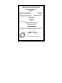
Declaration of Conformity
Aironet Model Number:
BR2000-E
Application of Council Directive:
Application of Council Directive:
89/336/EEC
72/23/EEC
CE Type Examination Certificate: HDTP/RDR/167/328880/11
Standards to which Conformity is Declared:
EN 55022 (B)
EN 55011 (B)
EN 50082-1
EN 60950
Manufacturer:
Aironet Wireless Communications, Inc.
367 Ghent Road, Suite 300
Fairlawn Ohio, 44333
The undersigned hereby declares that the equipment specified
above conforms to the directives and standards cited herein.
Michael Smedley
Director, Manufacturing Engineering
Aironet Wireless Communications, Inc.
iii
Declaration of Conformity
Aironet Model Number:
BR2040-E
Application of Council Directive:
Application of Council Directive:
CE Type Examination Certificate:
89/336/EEC
72/23/EEC
HDTP/RDR/167/377223
Standards to which Conformity is Declared:
EN 55022 (B)
EN 55011 (B)
EN 50082-1
EN 60950
Manufacturer:
Aironet Wireless Communications, Inc.
367 Ghent Road, Suite 300
Fairlawn Ohio, 44333
The undersigned hereby declares that the equipment specified
above conforms to the directives and standards cited herein.
Michael Smedley
Director, Manufacturing Engineering
Aironet Wireless Communications, Inc.
iv
Safety Information
The FCC with its action in General Docket 93-62, 1997, has
adopted a safety standard for human exposure to radio frequency
(RF) electromagnetic energy emitted by FCC regulated equipment. Aironet subscribes to the same safety standard for the use
of its products. Proper operation of this radio according to the
instructions in this manual will result in user exposure substantially
below the FCC recommended limits.
n
n
n
n
n
Do not move the BR1000-E/BR2000-E/ BR2040-E antenna(s)
while the unit is receiving or transmitting.
Do not hold any component containing a radio such that the
antenna(s) is(are) very close to, or touching, exposed parts of
the body, especially the face or eyes, while transmitting. Hold
such a component 15 centimeters (6 inches) or more from
your face.
Do not allow children to play with any radio equipment
containing a transmitter.
Do not operate a portable transmitter near unshielded
electrical blasting caps or in an explosive atmosphere unless
it is a type especially qualified for such use.
Do not turn on the BR1000-E/BR2000-E/ BR2040-E or
attempt to transmit data unless the antenna(s) is(are)
attached; if the antenna(s) is(are) not attached, the radio
module may be damaged.
The BR1000-E/BR2000-E/ BR2040-E are compliant with ANSI
C95.1.91 (1991).
v
Table of Contents
Introduction .........................................................................1
Wireless Bridge Overview..................................................2
Supporting Mixed Network Topologies...........................3
Adding In-Building Wireless Connectivity.......................4
System Configurations ...................................................5
Point-to-Point Wireless Bridge ...................................6
Point-to-Multipoint Wireless Bridge ............................7
Network Extension with Repeaters ............................9
Wireless Bridge with Wireless End Nodes ...............10
Radio Characteristics ...................................................11
Radio Network Terminology .....................................11
Understanding the Radio Network ...........................14
Before You Begin..............................................................15
Determining the Location for the Bridge.......................15
Indoor locations ........................................................15
Outdoor Locations ....................................................16
Installing the Hardware ....................................................17
Connecting the Antenna...............................................17
Connecting the Console Port Cable .............................18
Connecting the Ethernet Cable ....................................18
Connecting the 10Base2 Cable................................19
Connecting the 10Base5 Cable................................20
Connecting the 10BaseT (Twisted Pair) Cable ........21
Connecting the Power Pack .........................................22
Viewing the Bridge’s Top Panel Indicators...................23
Configuring the Wireless Bridge.....................................24
Using the Console Port ................................................24
Setting Configuration Parameters ................................26
Configuring the Radio Network ................................27
Setting Ethernet Parameters ....................................30
Disconnecting the Terminal..........................................30
vi
Where to Go from Here ....................................................31
Technical Support ............................................................31
Shipping Address .........................................................31
Communications ..........................................................31
Web Site.......................................................................31
Appendix A: Serial Cable Pinout.....................................32
Serial Port Pinout..........................................................33
Appendix B: Ethernet RJ-45 Cable..................................34
vii
viii
Introduction
Designed for linking networks together—typically in different
buildings—Aironet Wireless Bridges offer a low-cost
alternative to installing cable or dedicated telephone lines,
and are used when traditional wired LAN interconnections
are impractical. Rivers, rough terrain, private property and
highways can impede wired cable installation. Wireless
Bridges easily elude these challenges.
Now you can connect two or more buildings quickly and
easily with no expensive, time-consuming cable installation,
no right-of-way negotiations, and no monthly service fees
(unlike leased 56K, ISDN or T1 lines). By implementing an
Aironet wireless bridge solution, hundreds of your users can
experience speeds faster than 56K leased lines.
Aironet's field-proven wireless solutions deliver high-speed
network connectivity at a far lower cost than comparable
wired solutions. With no service fees required, you can save
hundreds—even thousands—of dollars per month.
Aironet Wireless Bridges establish radio links between two
or more networks up to 25 miles apart and move data
between buildings faster than T1 lines allowing all your PC
users to gain Internet access, email and network resources
housed in different buildings easily and efficiently.
Aironet Wireless Communications, Inc. has pioneered the
design and manufacture of wireless LAN products using
advanced spread spectrum radio technology for extremely
reliable data transmissions.
1
Wireless Bridge Overview
Aironet Wireless Bridges enable you to connect two or more
Token Ring and/or Ethernet networks to create a single
virtual LAN. The workstations on each LAN can communicate with each other over the Wireless Bridges as if they
were on the same physical LAN.
When connecting two or more LANs, each LAN uses an
Aironet Wireless Bridge and an antenna to transmit and
receive information between the LANs. Each RF-based
Bridge unit is connected to a LAN. Aironet offers a variety of
antennas to satisfy varying communication requirements
often dictated by premise considerations.
A wireless bridge appears as a single network node on the
wired LAN. It performs routing functions by moving packets
from the wireless LAN to remote workstations on the radio
network. Aironet Wireless Bridges support Direct Sequence
(DS) spread spectrum radios at frequencies of either 900
MHz or 2.4 GHz.
2
Supporting Mixed Network Topologies
To support mixed topologies, a Token Ring Bridge would be
installed to support a local Token Ring network and an
Ethernet Bridge would be installed to support a local
Ethernet network. The Aironet Ethernet and Token Ring
Bridges can then communicate with each other—linking
both types of networks into a single LAN.
You can connect an Aironet Wireless Token Ring Bridge
directly to Shielded Twisted Pair (STP) or Unshielded
Twisted Pair (UTP) network segments or a Wireless
Ethernet Bridge to 10Base2, 10Base5, or 10BaseT
segments.
3
If the existing network to which you are connecting the
Bridge is not Token Ring- or Ethernet-based, you can install
a Token Ring or Ethernet Network Interface Card (NIC) in
the File Server or third-party Bridge and accommodate other
network topologies.
Adding In-Building Wireless Connectivity
You can use an Aironet Wireless Bridge to support inbuilding wireless connections when local devices such as
fixed, portable or mobile devices are equipped with Aironet
wireless adapters. Aironet offers a wide array of wireless
adapters—supporting ISA, Micro Channel, PC Card, Serial
as well as Token Ring and Ethernet network infrastructures.
4
System Configurations
You can use wireless bridges in many different network
configurations. The way in which you configure your network determines the size of a network microcell (the area
for which a single Bridge provides radio coverage). You can
create multiple microcells on a LAN to extend your RF
coverage area.
The most common system configurations are:
• Point-to-Point Bridge
• Point-to-Multipoint Bridge
• Network extension with a Repeater
• Wireless Bridge with Wireless End Nodes
5
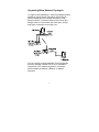
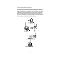
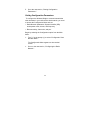
Point-to-Point Wireless Bridge
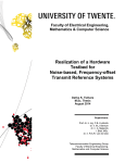
The Point-to-Point Wireless Bridge configuration (shown in
the following figure) uses two units to bridge two individual
LANs. Packets are sent between the File Server and Workstation B through the Bridge units (Root Unit and Remote
Node) over the radio link. Data packets sent from the File
Server to Workstation A go through the wired LAN segment
and do not go across the wireless radio link.
6
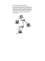
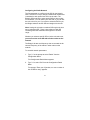
Point-to-Multipoint Wireless Bridge
When connecting three or more LANs (usually in different
buildings), each building requires an Aironet Wireless Bridge
and antenna. This is called a ‘multipoint’ bridge
configuration. One bridge is designated as the central site
and its antenna is configured to transmit and receive signals
from the bridges at the other sites. Generally, the central
site is equipped with an omni-directional antenna that
provides radio signal coverage in all directions. The other
bridges are typically served by directional antennas that
direct radio signals toward the central site.
Under a multipoint wireless bridge configuration, workstations on any of the LANs can communicate with other
workstations on their respective LAN or with any workstations on the remote LANs.
7
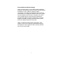
The following figure shows an example of a Point-toMultipoint configuration. Packets sent between Workstation
A and Workstation B are forwarded by their respective
bridges to the Root Unit. Then the Root Unit forwards these
packets back down to the appropriate bridge for routing to
the workstations. Packets sent between the File Server and
the remote workstations are routed through the Root Unit
and the appropriate Bridge.
8
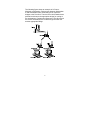
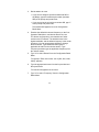
Network Extension with Repeaters
You can use bridges configured as repeaters to extend the
range of a wireless network beyond that of a single radio
hop. Repeaters can operate as either stand-alone units or
they can have LAN connections. (See the following figure.)
9
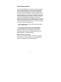
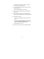
Wireless Bridge with Wireless End Nodes
You can configure a Wireless Bridge to send and receive
radio signals from in-building, radio-equipped devices at the
same time that it functions as a wireless bridge. By equipping fixed, portable or mobile devices with Aironet Wireless
Adapters, these devices can establish radio contact with the
Bridge and have wireless access to all local and remote
LANs, workstations and network resources. (See the
following figure.)
10
Radio Characteristics
Aironet Wireless Bridges use a radio modulation technique
known as Spread Spectrum Transmission. Spread Spectrum radios broadcast signals over a range of available
frequencies. The sending station uses a spreading code to
encode the signal. Only the receiving station that uses this
same spreading code can decode or "despread" the signal.
This lets the spread spectrum radio operate on a range of
frequencies with high data bandwidth and excellent
immunity from interference and multipath effects. Two Direct
Sequence (DS) spread spectrum radio models are offered
with the Wireless Bridges that differ in their frequency band
of operation and maximum data rate:
• Aironet 1000 Series of Wireless Bridges supporting the
902 - 928 MHz band.
• Aironet 2000 and 2040 Series of Wireless Bridges
supporting the 2400 - 2483.5 MHz (2.4 GHz) band.
Data is transmitted over a half-duplex radio channel
operating at data rates up to 860 Kbps (BR1000) and 2
Mbps (BR2000) or 4 Mbps (BR2040).
Radio Network Terminology
When you are reading this User’s Guide and configuring
your system, you may encounter some of the following
terms. You should become familiar with them.
11
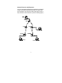
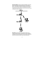
Wireless Network—Aironet’s Advanced Radio Local Area
Network (ARLAN) is designed as shown in the following
figure. This network structure shows that the Root Unit is at
the top of the wireless network, and Repeaters and radio
nodes branch down and away from the root to provide areas
of wireless network coverage.
Root Unit—An RF-based device that is at the top of a
wireless network structure. The Root Unit is the network’s
starting point and its Registration Table contains information
about other wireless network nodes associated with it.
12
Bridge—A device that connects two or more networks to
create a virtual network.
Remote Node—A non-Root Unit that communicates by
radio with the Root Unit.
Repeater—A device used to extend your network’s radio
range. A single Bridge is limited to a specific RF range. If
your system configuration includes nodes outside this range,
you need to add a Repeater for these nodes to
communicate.
Radio Node—A PC, File Server, notebook computer, etc.
that contains a Radio Card, LAN Adapter, or PCMCIA card.
End Node—A Radio Node located at the end of the wireless
radio network structure.
Parent/Child Node—The relationship between nodes on
the network. For example, The Root Unit in the preceding
figure is the parent of the other nodes in the network
structure. Likewise, the End Nodes are the Children of the
Root Unit.
Registration—Each Wireless Bridge on the Radio Network
has a Registration table that controls packet routing from the
wired LAN to the Radio network. This table maintains
entries for all radio nodes below the selected Wireless
Bridge in the network. This table determines data packet
routing.
13
Understanding the Radio Network
The preceding figure shows a simplified graphic illustration
of a Radio Network. In this example shown, the Root Unit
does not register but accepts registration from those nodes
within Radio Range (The Repeater and top End Node).
The Repeater registers to the Root Unit and accepts
registrations from nodes in its radio range (the bottom End
Node).
The End Node now registers to the Repeater as if it is the
closest Wireless Bridge in Radio Range. Then, the
Repeater passes the End Node’s registrations to its parent,
the Root Unit. Now the Root Unit has registration for all the
nodes.
14
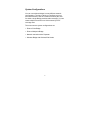
Before You Begin
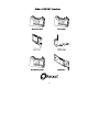
Unpack your Wireless Bridge. Make sure the following items
are present and in good condition:
• Wireless Bridge (Ethernet model)
• 120VAC/60Hz to 12-18VDC Power Pack or 90-264
VAC/47-63Hz to 12-18VDC Universal Power Pack
• Standard 2dB Dipole Antenna
If any item is damaged or missing, contact your retailer.
Save all shipping and packing material to repack the unit in
the future if servicing is required.
Determining the Location for the Bridge
Before you begin installation and configuration, determine
where you want to put the Wireless Bridge. Because the
Bridge is a radio device, you need to make decisions
regarding the location of the Bridge and its antenna to
provide optimum radio range and performance. You can use
the Bridge in both indoor and outdoor Radio network
environments.
Indoor locations
The radio ranges for indoor locations depend on the
following:
Antenna type and placement: To maximize a radio’s range
indoors, you should try to place the Bridge’s antenna as high
as is possible (but below the ceiling to reduce interference).
For additional antenna solutions, please contact your
Aironet representative.
15
Environment openness: The less cluttered and open your
work environment, the greater the Bridge’s radio range.
Building materials: The floor-to-floor penetration of the
Bridge’s radio depends on the materials in your building’s
construction. For example, the radios will achieve a greater
range when used in buildings that have drywall rather than
concrete block walls.
Outdoor Locations
Radio ranges for outdoor locations are basically determined
by antenna elevation, path clearances, and line-of-sight
considerations.
Outdoor applications will achieve greater radio ranges when
the antenna is elevated as high as possible.
Line of Sight—When considering line of sight criteria be
sure that there are no obstructions between antennas. You
can attain ranges up to 300 meters (1,000 feet) with 1.8
meters (6 feet) elevation of both antennas and up to 40
kilometers (25 miles) with directional antennas at both ends
and appropriate elevation and maximum path clearance.
16
Installing the Hardware
Use the following procedures to install the Wireless Bridge
hardware.
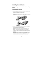
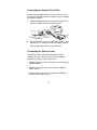
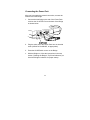
Connecting the Antenna
1. With the Bridge powered off, attach the antenna to the
antenna connector as shown below.
Connect the antenna until it is finger-tight. Do not overtighten.
2. After it is connected, position the antenna vertically to
achieve an omni-directional pattern.
Note: If you are using a remote antenna with your
Bridge, connect the coaxial cable to the Antenna
connector. Only use antennas and cables supplied by
Aironet.
Note: Because of changes in FCC and DOC regulations, the antenna connector on the Bridge is the
reverse polarity of the standard TNC connector.
17
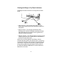
Connecting the Console Port Cable
Connecting the Bridge’s console port to a terminal or to a
PC running a terminal emulation program lets you configure
the Bridge’s software.
1. With the Bridge powered off, connect the console port
cable to the EIA-232-E port as shown below.
2. Connect the other end of the cable to the serial port of a
terminal or a PC running a terminal emulation program.
Make sure the terminal or PC is powered off.
Connecting the Ethernet Cable
The Ethernet model of the Wireless Bridge supports
10Base2 (Thinnet), 10Base5 (Thicknet), and 10BaseT
(twisted pair) cabling. If your system uses:
• 10Base2 cabling, go to the next section, "Connecting the
10Base2 Cable."
• 10Base5 cabling, go to the "Connecting the 10Base5
Cable" section.
• 10BaseT cabling, go to the "Connecting the 10BaseT
(Twisted Pair) Cable" section.
18
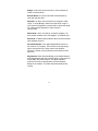
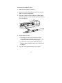
Connecting the 10Base2 Cable
1. Make sure the Bridge is turned off.
2. Connect one end of the Ethernet cable to one end of a
BNC T-connector (if applicable).
3. Slide the T-connector onto the Bridge’s 10Base2 BNC
connector and turn it until it locks into place, as shown in
the following figure.
4. Decide what to do next:
• If the Bridge is at the end of the Ethernet cable,
connect a 50-ohm terminator to the open end of the
T-connector (shown in the preceding figure).
• If it is not at the end, connect another end of the
Ethernet cable to the other end of the T-connector on
the Bridge.
5. Go to the "Connecting the Power Pack" section.
19
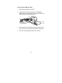
Connecting the 10Base5 Cable
1. Make sure the Bridge is turned off.
2. Connect the Transceiver Connector to the Bridge’s
10Base5 AUI port, and slide the locking mechanism into
place (shown in the following figure).
3. Connect the other Transceiver Connector at the end of
the Transceiver drop cable to the External Transceiver.
4. Go to the "Connecting the Power Pack" section.
20
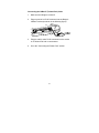
Connecting the 10BaseT (Twisted Pair) Cable
1. Make sure the Bridge is turned off.
2. Plug one end of an RJ-45 connector into the Bridge’s
10BaseT socket (as shown in the following figure).
3. Plug the cable’s other RJ-45 connector into the socket
on a Twisted Pair hub or concentrator.
4. Go to the "Connecting the Power Pack" section.
21
Connecting the Power Pack
After you have made the network connection, connect the
Power Pack to the Bridge.
1. Connect the small plug on the end of the Power Pack
cord into the 12-18VDC Port on the back of the Bridge
as shown below.
2. Plug the other end of the Power Pack into an electrical
outlet (120VACor 90-240VAC, as appropriate).
3. Press the On/Off Switch to turn on the Bridge.
4.
With the Bridge on, follow the instructions in the next
section ("Viewing the Bridge’s Top Panel Indicators") to
check the Bridge’s indicators for proper startup.
22
Viewing the Bridge’s Top Panel Indicators
The Bridge has three Indicators on its top panel as shown
below.
• Radio Indicator—This indicates radio traffic activity; it
flashes green whenever the radio transmits or receives a
data packet.
• Status Indicator—This indicates operational status;
flashing green indicates the Bridge is operating normally.
When the Bridge has accepted a Radio registration the
indicator becomes solid green.
• Network Indicator—This indicates Ethernet network activity;
it flashes green whenever a data packet is transmitted or
received over the network link.
When power is initially applied to the Bridge, all three
Indicators will flash yellow, red and then green, in sequence,
to test the functionality of the Indicators. The Power-On Self
Test follows. If any power-on test fails, the Status Indicator
will go solid red and the unit will stop functioning. Refer to
the BR1000-E/BR2000-E/BR2040-E Technical Reference
Manual for error codes.
23
Configuring the Wireless Bridge
Use the Bridge’s Console Port and the Console System to
configure the unit to communicate with the rest of your network. The Console System consists of a series of menus
from which you can change and set Bridge parameters to
conform with your network.
Using the Console Port
You can access the Console Port directly by connecting a
straight through serial cable between the Bridge’s console
(serial) port and a terminal or PC running a terminal emulation program. When you installed the Bridge hardware, you
connected a serial cable to this port and to a terminal or PC.
To begin using the Console System:
1. Set the communication parameters of the terminal or
PC running the terminal emulation software to the
following:
• 9600 baud
• No parity
• 8 data bits
• 1 stop bit
• Xon/Xoff flow control
2. Start the communication session between your terminal
or PC and the Bridge.
3. After the Bridge is powered up, the following message
appears on the terminal’s screen:
Are you using an ANSI compatible terminal [y/n]:
24
• If you are using an ANSI compatible terminal, type "y"
at the prompt and press Enter.
Note: An ANSI terminal shows you formatted text and
clears the screen before each new screen displays.
• If you are using a Teletype (TTY) terminal, type "n" at
the prompt and press Enter.
Note: The TTY terminal scrolls information as it
arrives at the terminal’s screen.
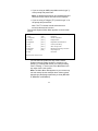
The Console System’s Main Menu appears on the terminal
screen:
ARLAN 64x Vx.x
Option
Main Menu
64x_123456
Value
Description
1 - Configuration
[ menu ]
- General configuration
2 - Statistics
[ menu ]
- Display statistics
3 - Registration
[ menu ]
- Registration table maintenance
4 - Filter
[ menu ]
- Control packet filtering
5 - Logs
[ menu ]
- Alarm and log control
6 - Diagnostics
[ menu ]
- Maintenance and testing commands
7 - Privilege
[ write ]
- Set privilege level
8 - Help
- Introduction
Enter an option number or name
>
You can select an option from any of the Console
System menus by typing its name or number at the
prompt (>). Pressing Esc returns you to the preceding
menu. Pressing "=" returns you to the Main Menu from
any other menu in the system.
Note: The Main Menu that appears on your screen may
not look exactly like the example above. Menu options
depend upon the Bridge model that you have (BR1000E, BR2000-E or BR2040-E).
25
5. Go to the next section, "Setting Configuration
Parameters."
Setting Configuration Parameters
To configure the Wireless Bridge to communicate with the
other elements in your radio and/or wired network, you need
to access the Configuration Menu and set:
• Radio Network parameters: System Identifier (SID),
root/repeater mode, bit rate, and frequency
• Ethernet activity, frame size, and port
Begin by selecting the Configuration option from the Main
Menu.
1. Type "1" at the prompt (>) to select "Configuration" from
the Main Menu.
The Configuration Menu appears on the terminal
screen.
2.
Go on to the next section, "Configuring the Radio
Network."
26
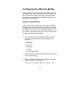
Configuring the Radio Network
The first parameter to configure is the SID for the bridge’s
radio. The SID is a unique, 6-digit, hexadecimal number that
is attached to each packet sent out over the radio. The
Bridge’s SID must be the same as the SIDs of other nodes
on its network. You can select your own SID, or you can ask
the unit to do it for you. If you ask it to select an SID for you,
the Bridge selects a random SID and assigns it to the unit.
Note: Letting the unit select a random SID may be the best
way to select the SID. There is less chance of this SID
conflicting with other networks that might be in its radio
range.
Whether you select a specific SID or let the unit select one,
you must use the same SID with all other nodes on the
network.
The Bridge’s bit rate and frequency also must match the bit
rate and frequency of the radios in other nodes on the
network.
To set radio network parameters:
1. Type "1" at the prompt to select "Radio" from the
Configuration Menu.
The Configuration Radio Menu appears.
2. Type "1" to select "Sid" from the Configuration Radio
Menu.
The prompt: "Enter one of [random, an even number in
hex of ffffffh or less]" appears.
27
3. Decide what to do next:
• If you want to assign a specific hexadecimal SID to
the Bridge, type the hexadecimal number (less than
ffffff) at the prompt and press Enter.
• If you want to let the unit select a random SID, type "r"
at the prompt and press Enter.
The selected SID appears at on the Configuration
Radio Menu.
4. Examine the default bit rate and frequency on the Configuration Radio Menu, and decide what to do next:
The bit rate and frequency must match that of other
nodes on the RF network. The default bit rate is the
highest available, and the default frequency is the center
frequency. You can accept these defaults or change
them as follows. Type Bitrate and then type the
applicable bit rate from the choices shown. Type
Frequency and then type the applicable frequency from
the choices shown.
5. Type "2" to select "Bitrate" from the Configuration Radio
Menu.
The prompt: "Enter rate in kb/s, one of [354, 500, 1000,
2000]:" appears.
6. Type the appropriate bit rate from the list provided and
then press Enter.
The new bit rate appears on the menu.
7. Type "3" to select "Frequency" from the Configuration
Radio Menu.
28
The prompt: "Enter frequency in MHz, one of [2412,
2427, 2442, 2457, 2465]:" appears.
8. Type the appropriate frequency from the list provided
and then press Enter.
The new frequency appears on the menu.
9. Type "4" to select "Distance" from the Configuration
Radio menu.
10. Type the maximum distance (in kilometers) between
this bridge and its farthest partner and then press Enter.
11. Decide what to do next:
• If you are using the Bridge as a Root Unit, go on to
Step 12.
• If you are not using the Bridge as a Root Unit or you
are using it as a Repeater Bridge, type "5" to select
"Root" from the Radio Configuration Menu.
The Root option is set to "off".
12. Press the Esc key to return to the Configuration Menu.
29
Setting Ethernet Parameters
The Ethernet port has three parameters (Active, Size, and
Port) whose default settings are already correct for most
basic installations. You should probably need to make no
changes to any of the Ethernet parameters. Go on to the
"Disconnecting the Terminal" section. If you require
additional information refer to the BR1000-E/BR2000E/BR2040-E Technical Reference Manual.
Disconnecting the Terminal
With the initial configuration of the unit finished, you need to
end the terminal session and disconnect the terminal (or
PC) from the Bridge’s serial port.
1. Power-off the Bridge.
2.
Remove the serial cable connector from the
Bridge’s EIA-232-E port.
3.
Power-on the Bridge.
30
Where to Go from Here
Please ask your Aironet representative for the BR1000E/BR2000-E/BR2040-E Technical Reference Manual.
Read the Technical Reference Manual to learn more details
about your Aironet unit and ARLAN software. Use the
instructions in this reference to view statistics and perform
system diagnostics.
Technical Support
Shipping Address
Aironet Wireless Communications, Inc.
367 Ghent Road, Suite 300
Fairlawn, Ohio 44333
Communications
Telephone - (800) 705-5555
Fax - (330) 664-7990
e-mail - [email protected]
Web Site
http://www.aironet.com
31
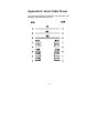
Appendix A: Serial Cable Pinout
A typical Wireless Bridge serial cable is a 9-pin cable. The
following diagram shows its pinout.
32
Serial Port Pinout
9-Pin AT
Name
Abbr.
DTE
3
Transmit Data
TD
Output>
2
Receive Data
RD
Input<
7
Request to Send
RTS
Output>
8
Clear to Send
CTS
Input<
6
Data Set Ready
DSR
Input<
5
Signal Ground
SG
1
Data Carrier Detect
DCD
Input<
4
Data Terminal Ready
DTR
Output>
Ring Indicator
RI
Input<
9 N/C
• The “DTE” column indicates the data direction in terms of
the DTE.
• The “9-Pin AT” column indicates the pin numbers used on
the Console Port connector.
33
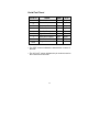
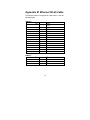
Appendix B: Ethernet RJ-45 Cable
The Ethernet cable is configured as a Hub device. See the
following figure.
10Base5
Pin 1
2
3
4
5
6
7
8
9
10
11
12
13
14
15
GND
CN+
TX+
GND
RX+
GND
NC
GND
CNTXGND
RX12V
NC
NC
Pin 1
2
3
6
TD+
TDRD+
RD-
10BaseT
34
35
36