1
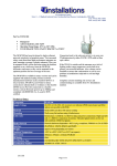
User’s Guide
2200 and 1200 series
Wireless Access Points for
Ethernet
Products supported:
AP2200-E and AP1200-E
DOC-710-003848 Rev. B0
Aironet Wireless Communications, Inc. • 367 Ghent Road, Suite 300
P.O. Box 5292 • Fairlawn, Ohio 44334-0292
Aironet Wireless Communications, Inc.
No part of this document may be reproduced or transmitted in any means,
electronic or mechanical, for any purpose, without the written permission of
Aironet. Information in this document is subject to change without notice.
Aironet makes no representation or warranties with respect to the contents of
this manual and specifically disclaims any express or implied warranties of
merchantability or fitness for any particular purpose.
© 1998 Aironet Wireless Communications, Inc.
All rights reserved.
ARLAN® & Aironet® are trademarks of Aironet Wireless Communications, Inc.
Printed in USA
DOC-710-003848 Rev. B0
Manufacturers Federal Communication Commission
Declaration of Conformity Statement
Models : AP1200-E, AP2200-E
Manufacturer :
Aironet Wireless Communications, Inc.
367 Ghent Rd , Suite 300
Fairlawn, OH 44333
1-800-3-WIRELESS
This device complies with Part 15 rules. Operation is subject to the following two conditions:
1) this device may cause harmful interference, and 2) this device must
accept any interference received, including interference that may cause
undesired operation.
This equipment has been tested and found to comply with the limits of a
Class B digital device, pursuant to Part 15 of the FCC Rules. These limits
are designed to provide reasonable protection against harmful interference
when the equipment is operated in a residential environment. This equipment generates, uses, and radiates radio frequency energy, and if not
installed and used in accordance with the instructions, may cause harmful
interference. However there is no guarantee that interference will not
occur. If this equipment does cause interference to radio or television
reception, which can be determined by turning the equipment off and on,
the user is encouraged to correct the interference by one of the following
measures:
l Reorient or relocate the receiving antenna.
l Increase separation between the equipment and receiver.
l Connect the equipment into an outlet on a circuit different from
which the receiver is connected.
l Consult the dealer or an experienced radio/TV technician.
User Warning
The Part 15 radio device operates on a non-interference basis with
other devices operating at this frequency. Any changes or
modification to said product not expressly approved by Aironet could
void the user’s authority to operate this device.
i
Department of Communications - Canada
Canadian Compliance Statement
This Class B Digital apparatus meets all the requirements of the Canadian
Interference-Causing Equipment Regulations.
Cet appareil numerique de la classe B respecte les exigences du
Reglement sur le material broilleur du Canada.
This device complies with RSS-210 of Industry of Canada. Operation is
subject to the following two conditions: 1) this device may cause harmful
interference, and 2) this device must accept any interference received,
including interference that may cause undesired operation.
European Telecommunication Standards Institute
Statement of Compliance
Information to User
This equipment has been tested and found to comply with the European
Telecommunications Standard ETS 300.328. This standard covers Wideband Data Transmission Systems referred in CEPT recommendation T/R
10.01.
This type of accepted equipment is designed to provide reasonable
protection against harmful interference when the equipment is operated in
a commercial environment. This equipment generates, uses, and can
radiate radio frequency energy, and if not installed and used in accordance
with the instruction manual, may cause harmful interference to radio
communications.
ii
Declaration of Conformity
Aironet Model Number:
AP2200-E
Application of Council Directive:
Application of Council Directive:
89/336/EEC
72/23/EEC
CE Type Examination Certificate: HDTP/RDR/167/328880/11
Standards to which Conformity is Declared:
EN 55022 (B)
EN 55011 (B)
EN 50082-1
EN 60950
Manufacturer:
Aironet Wireless Communications, Inc.
367 Ghent Road, Suite 300
Fairlawn Ohio, 44333
The undersigned hereby declares that the equipment specified
above conforms to the directives and standards cited herein.
Michael Smedley
Director, Manufacturing Engineering
Aironet Wireless Communications, Inc.
iii
Safety Information
The FCC with its action in General Docket 93-62, 1997, has
adopted a safety standard for human exposure to radio frequency
(RF) electromagnetic energy emitted by FCC regulated equipment. Aironet subscribes to the same safety standard for the use
of its products. Proper operation of this radio according to the
instructions in this manual will result in user exposure substantially
below the FCC recommended limits.
n
n
n
n
n
Do not move the AP1200-E/AP2200-E antenna(s) while the
unit is receiving or transmitting.
Do not hold any component containing a radio such that the
antenna(s) is(are) very close to, or touching, exposed parts of
the body, especially the face or eyes, while transmitting. Hold
such a component 15 centimeters (6 inches) or more from
your face.
Do not allow children to play with any radio equipment
containing a transmitter.
Do not operate a portable transmitter near unshielded
electrical blasting caps or in an explosive atmosphere unless
it is a type especially qualified for such use.
Do not turn on the AP1200-E/AP2200-E or attempt to transmit
data unless the antenna(s) is(are) attached; if the antenna(s)
is(are) not attached, the radio module may be damaged.
The AP1200-E/AP2200-E are compliant with ANSI C95.1.91
(1991).
iv
Table of Contents
Before You Start .................................................................1
Terminology ........................................................................1
Understanding the Radio Network....................................2
Installing the Hardware ......................................................4
Configuring the Access Point............................................8
Console Port...................................................................8
Telnet Session................................................................8
System Identifier (SID) ...................................................9
Bitrate/Frequency (2200 Series/2.4 GHz Models)..........9
Channel (1200 Series/900MHz Models) ......................10
Root Mode....................................................................10
Verifying Registration ...................................................10
Where to Go from Here ....................................................11
Technical Support ............................................................11
Shipping Address .........................................................11
Communications ..........................................................11
Web Site.......................................................................11
v
vi
The purpose of this User’s Guide is to allow you to install
and configure your Access Point so that an end node or
another Access Point (acting as a Repeater) will be able to
register to it. For detailed installation and configuration
procedures, see the AP1200-E/AP2200-E Technical
Reference Manual.
Before You Start
After unpacking the system, make sure the following items
are present and in good condition.
• Wireless Access Point — 2200 or 1200 series
• 120VAC/60Hz or 90-264VAC/47-63Hz to 12-18VDC
Power Pack
• Standard 2dB Dipole Antenna
If any item is damaged or missing, contact your Reseller.
Save all shipping and packing material to repack the unit in
the future, should service be required.
Terminology
Root Unit - An Access Point which is located at the top of a
RF Network Tree. The Root Unit is the starting point in the
network and contains information in its Registration Table
regarding all nodes on the network.
Repeater - A Repeater is an Access Point which is used to
extend the radio range of your RF Network. A single Access
Point has a limited RF range. If your system configuration
includes nodes outside this range, you will need to add a
Repeater in order for them to communicate.
1
Radio Node - A PC, notebook computer, etc. containing a
Wireless LAN ISA, MCA card or PCMCIA Adapter.
End Node - A Radio Node that is at the end of the RF
Network Tree.
Understanding the Radio Network
Advanced Radio Local Area Network (ARLAN) is designed
like an upside-down tree, with a Root Unit at the top, and
repeaters and Radio nodes branching down and out from
the Root as shown in the figure below.
Wireless Access Points can serve as a Root Unit or Repeater, providing wireless data communications between
the Ethernet based network and other end nodes, or within
the radio network itself.
In the example shown,
the Root Unit does not
register, but will accept
Registration from those
nodes within Radio
Range (The Repeater)
The Repeater registers to
the Root Unit and will
accept registrations from
the End Nodes within
radio range.
The Repeater will pass
along the End Nodes’
registrations to its parent,
the Root Unit.
2
The Root Unit will have registration information for all nodes
on the radio network in the tree.
Optional long range antennas are shown below; a range of 6
miles can be achieved with the 900MHz Yagi and 4 Miles
with the 2.4GHz Yagi.
3
Installing the Hardware
With the unit powered off, attach the RP-TNC antenna to
the antenna connector.
Do not over-tighten when connecting, finger-tight is
sufficient. Once connected, make sure the antenna is
positioned vertically to achieve an omni-directional pattern.
Attach the console port cable to the EIA-232-E port and the
other end of the cable to the serial port on a terminal, or PC
running a terminal emulation program.
4
If using Thinnet cabling, attach the cable to each end of
a BNC T-connector, if applicable, then slide the
T-connector onto the unit’s 10Base2 BNC connector.
If the Access Point is at the end of the Ethernet cable, a 50ohm terminator must be installed on the open end of the Tconnector.
If using 10Base5 (Thicknet) cabling, attach the
Transceiver Connector to the unit’s 10Base5 AUI Port. Slide
the locking mechanism in place. The other end of the
Transceiver drop cabling should connect to an External
Transceiver.
5
If using 10BaseT (Twisted Pair) cabling, plug the RJ-45
connector into the 10BaseT (Twisted Pair) socket and
connect the other end of the cabling to a Twisted Pair hub or
concentrator.
Insert the small plug on the end of the AC/DC Power Pack
Cord into the 12-18VDC port, then plug the AC/DC power
pack into an electrical outlet.
Power-on the Access Point by pushing the ON button.
6
When power is initially applied to the Access Point, all three
Indicators will flash yellow, red and then green, in sequence,
to test the functionality of the Indicators. The Power-On Self
Test follows. If any power-on test fails, the Status Indicator
will go solid red and the unit will stop functioning.
7
Configuring the Access Point
To configure the Access Point to communicate with end
nodes or repeaters, you must first use the Console Port to
set the following parameters - SID, Bitrate/Frequency (or
Channel), Root Mode. If you set an IP address now, you will
be able to Telnet to the unit.
The Console Port can be accessed directly by connecting
the Access Point to an EIA-232-E terminal emulation
program or by running a Telnet session from a remote on a
network.
Console Port
To start the Console Port, set the EIA-232-E terminal (or PC
running a terminal emulation program) to 9600 Baud, NoParity, 8 data bits and 1 stop bit.
Power-on the Access Point and the terminal and then type
Yes or No when prompted for the ANSI or Teletype
command.
The Console Port consists of a main menu and a series of
sub-menus containing the configuration parameters. Simply
type the name of the parameter or the menu number and
then press ENTER.
Telnet Session
Telnet sessions can be disabled under Configuration
Console Telnet Off
Before starting a Telnet session to a remote Access Point,
you must first assign the unit an IP Address.
8
From the Main Menu, type Configuration Ident Inaddr and
then type the applicable address.
System Identifier (SID)
The SID is a unique identifier that is attached to each packet
sent out over the radio. You must make sure that the
Access Point is set with the same SID as the other nodes
on the network with which you would like to share RF
communication.
You can either set your own SID or ask the unit to pick a
random value for you. This is probably the best way to pick
a SID as there is less chance of conflicting with other
networks that may be in radio range. You may use only one
unit to pick the random value. This same value must be
used on all other devices on this system.
At the Console Port, type Configuration Radio SID and then
enter an even HEX number not exceeding 6 digits, or select
random if you want the Access Point to pick the SID.
Bitrate/Frequency (2200 Series/2.4 GHz Models)
The bit rate and frequency must match those of other nodes
on the RF network. The default bit rate is the highest
available, and the default frequency is the center frequency.
You can accept these defaults or change them as follows.
Type Bitrate and then type the applicable bit rate from the
choices shown. Type Frequency and then type the
applicable frequency from the choices shown.
9
Channel (1200 Series/900MHz Models)
The channel must match that of other nodes on the RF
network. The default channel is the center frequency with
the highest data rate. Since each channel is matched to a
bit rate, changing the channel will also change the bit rate.
Type Channel and then type the applicable channel from the
choices shown. See Appendix D in the AP1200-E/AP2200-E
Technical Reference Manual for more details.
Root Mode
If your Access Point is serving as a repeater (no
connections to the backbone) you should set root mode to
“Off” as follows:
Type Configuration-Radio-Root and then type “Y”
in response to the argument prompt.
Verifying Registration
Once you have configured your Access Point with the
correct parameters and the end nodes are correctly
configured, RF communication may begin. The Radio
Indicator will flash “green” indicating RF data traffic. The
Status Indicator will be “solid green” indicating that one or
more nodes have registered to the unit.
10
Where to Go from Here
Please ask your Aironet representative for the
AP1200-E/AP2200-E Technical Reference Manual.
In the Technical Reference Manual, you can learn more
details about your Aironet unit and ARLAN software. Use
the instructions in this reference to view statistics and
perform system diagnostics.
Technical Support
Shipping Address
Aironet Wireless Communications, Inc.
367 Ghent Road, Suite 300
Fairlawn, Ohio 44333
Communications
Telephone - (800) 705-5555
Fax - (330) 664-7990
e-mail - [email protected]
Web Site
http://www.aironet.com
11
12