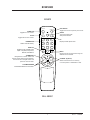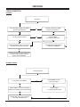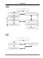
1
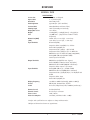
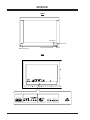
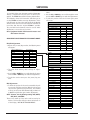
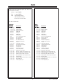
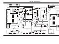
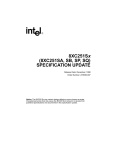
SERVICE MANUAL Product Type: Manual Part#: Chassis: Product Year: Model Series: DPDP40 MU40PA10B PLASMA 923-03472 PDP 40” 2001 Service Manual is a part the Service Kit. Manual is to remain with Service Kit. CONTENTS OVERVIEW ........................................................ 5 TROUBLESHOOTING ............................................. 8 ADJUSTMENTS ................................................. 10 PARTS ............................................................ 12 DIAGRAMS ...................................................... 13 SCHEMATICS .................................................... 20 Published by Technical Publications LG & Zenith Electronics Corporation P.O. Box 240007 Huntsville, Alabama 35824 Copyright Made/Printed in the U.S.A. August 2001 by LG & Zenith Electronics Corporation PRODUCT SAFETY GUIDELINES IMPORTANT SAFETY NOTICE A.C. Voltmeter This manual was prepared for use only by properly trained audio-visual service technicians. When servicing this product, under no circumstances should the original design be modified or altered without permission from Zenith Electronics Corporation. All components should be replaced only with types identical to those in the original circuit and their physical location, wiring and lead dress must conform to original layout upon completion of repairs. Special components are also used to prevent x-radiation, shock and fire hazard. These components are indicated by the letter “x” included in their component designators and are required to maintain safe performance. No deviations are allowed without prior approval by Zenith Electronics Corporation. 0.15uF Good Earth Ground such as the Water Pipe, Conduit, etc. Circuit diagrams may occasionally differ from the actual circuit used. This way, implementation of the latest safety and performance improvement changes into the set is not delayed until the new service literature is printed. 1500 OHM Place this probe on each exposed metal part. 10 WATT X-RADIATION CAUTION: Do not attempt to modify this product in any way. Never perform customized installations without manufacturer’s approval. Unauthorized modifications will not only void the warranty, but may lead to property damage or user injury. 1. Be sure procedures and instructions to all service personnel cover the subject of x-radiation. The only potential source of x-rays in current TV receivers is the picture tube. However, this tube does not emit x-rays when the HV is at the factory-specified level. The proper value is given in the applicable schematic. Operation at higher voltages may cause a failure of the picture tube or high-voltage supply and, under certain circumstances may produce radiation in excess of desirable levels. 2. Only factory-specified CRT anode connectors must be used. 3. It is essential that the service personnel have available an accurate and reliable high-voltage meter. 4. When the high-voltage circuitry is operating properly, there is no possibility of an x-radiation problem. Every time a color chassis is serviced, the brightness should be run up and down while monitoring the high voltage with a meter, to be certain that the high voltage does not exceed the specified value and that it is regulating correctly. 5. When troubleshooting and making test measurements in a product with a problem of excessively high voltage, avoid being unnecessarily close to the picture tube and the high voltage power supply. Do not operate the product longer than necessary to locate the cause of excessive voltage. 6. Refer to HV, B+, and shutdown adjustment procedures described in the appropriate schematics and diagrams (where used). Service work should be performed only after you are thoroughly familiar with these safety checks and servicing guidelines. GRAPHIC SYMBOLS The exclamation point within an equilateral triangle is intended to alert the service personnel to important safety information in the service literature. The lightning flash with arrowhead symbol within an equilateral triangle is intended to alert the service personnel to the presence of noninsulated “dangerous voltage” that may be of sufficient magnitude to constitute a risk of electric shock. The pictorial representation of a fuse and its rating within an equilateral triangle is intended to convey to the service personnel the following fuse replacement caution notice: CAUTION: FOR CONTINUED PROTECTION AGAINST RISK OF FIRE, REPLACE ALL FUSES WITH THE SAME TYPE AND RATING AS MARKED NEAR EACH FUSE. SERVICE INFORMATION IMPLOSION While servicing, use an isolation transformer for protection from AC line shock. After the original service problem has been corrected, make a check of the following: FIRE AND SHOCK HAZARD 1. Be sure that all components are positioned to avoid a possibility of adjacent component shorts. This is especially important on items transported to and from the repair shop. 1. All direct view picture tubes are equipped with an integral implosion protection system; take care to avoid damage during installation. 2. Use only the recommended factory replacement tubes. TIPS ON PROPER INSTALLATION 2. Verify that all protective devices such as insulators, barriers, covers, shields, strain reliefs, power supply cords, and other hardware have been reinstalled per the original design. Be sure that the safety purpose of the polarized line plug has not been defeated. 3. Soldering must be inspected to discover possible cold solder joints, solder splashes, or sharp solder points. Be certain to remove all loose foreign particles. 4. Check for physical evidence of damage or deterioration to parts and components, for frayed leads or damaged insulation (including the AC cord), and replace if necessary. 1. Never install any receiver in a closed-in recess, cubbyhole, or closely fitting shelf space over, or close to, a heat duct, or in the path of heated air flow. 2. Avoid conditions of high humidity such as: outdoor patio installations where dew is a factor, near steam radiators where steam leakage is a factor, etc. 3. Avoid placement where draperies may obstruct venting. The customer should also avoid the use of decorative scarves or other coverings that might obstruct ventilation. 4. Wall- and shelf-mounted installations using a commercial mounting kit must follow the factory-approved mounting instructions. A product mounted to a shelf or platform must retain its original feet (or the equivalent thickness in spacers) to provide adequate air flow across the bottom. Bolts or screws used for fasteners must not touch any parts or wiring. Perform leakage tests on customized installations. 5. Caution customers against mounting a product on a sloping shelf or in a tilted position, unless the receiver is properly secured. 6. A product on a roll-about cart should be stable in its mounting to the cart. Caution the customer on the hazards of trying to roll a cart with small casters across thresholds or deep pile carpets. 7. Caution customers against using a cart or stand that has not been listed by Underwriters Laboratories, Inc. for use with its specific model of television receiver or generically approved for use with TVs of the same or larger screen size. 8. Caution customers against using extension cords. Explain that a forest of extensions, sprouting from a single outlet, can lead to disastrous consequences to home and family. 5. No lead or component should touch a receiving tube or a resistor rated at 1 watt or more. Lead tension around protruding metal surfaces must be avoided. 6. After reassembly of the set, always perform an AC leakage test on all exposed metallic parts of the cabinet (the channel selector knobs, antenna terminals, handle and screws) to be sure that set is safe to operate without danger of electrical shock. DO NOT USE A LINE ISOLATION TRANSFORMER DURING THIS TEST. Use an AC voltmeter having 5000 ohms per volt or more sensitivity in the following manner: Connect a 1500 ohm, 10 watt resistor, paralleled by a .15 mfd 150V AC type capacitor between a known good earth ground water pipe, conduit, etc.) and the exposed metallic parts, one at a time. Measure the AC voltage across the combination of 1500 ohm resistor and .15 mfd capacitor. Reverse the AC plug by using a non-polarized adaptor and repeat AC voltage measurements for each exposed metallic part. Voltage measured must not exceed 0.75 volts RMS. This corresponds to 0.5 milliamp AC. Any value exceeding this limit constitutes a potential shock hazard and must be corrected immediately. 2 PDP 40” - SAFETY TABLE OF CONTENTS OVERVIEW ........................................................ 5 SPECIFICATIONS ............................................. 5 CONNECTIONS/CONTROLS .................................. 6 REMOTE ........................................................ 7 TROUBLESHOOTING ............................................. 8 NO POWER ..................................................... 8 ABNORMAL PICTURE ....................................... 8 NO RASTER .................................................... 9 NO SOUND ..................................................... 9 ADJUSTMENT INSTRUCTIONS ............................... 10 PRECAUTIONS .............................................. 10 VOLTAGE ADJUSTMENTS ................................. 10 RGB CUTOFF ................................................ 10 COLOR TEMPERATURE .................................... 10 VIF VCO ...................................................... 11 AGC ........................................................... 11 OPTION TABLE.............................................. 11 PARTS ............................................................ 13 DIAGRAMS ...................................................... 14 EXPLODED VIEW ........................................... 14 INTERCONNECT ............................................. 15 PHOTO / MODULE LAYOUT .............................. 16 BLOCK DIAGRAMS ......................................... 17 VIDEO SCAN CONVERTER PCB TOP .................... 18 VIDEO SCAN CONVERTER BOTTOM ..................... 19 ADDITIONAL PCB .......................................... 20 SCHEMATICS .................................................... 21 VIDEO SCAN CONVERTER CIRCUIT ..................... 21 3 PDP 40” - TOC Overview OVERVIEW GENERAL INFO Screen Size Aspect Ratio Resolution Peak Brightness Contrast Ratio Viewing Angle Displayable Colors Weight Life Dimensions(MNT) (SPK) Input Terminals Output Terminals Input Terminals Display Frequency Picture Sound SPECIFICATIONS 40 in/101 cm diagonal 4 :3 (width:height) 640 x 480 pixels typ.330cd/m² (with 45%filter) 550:1(Dark Room with 45% filter) 160° horizontally and vertically 16.7 million 32.55kg(MNT), 6.45kg(D/Stand), 3.1kg(Spk.)x2 >25,000 hours (elapsed time to 50% of initial brightness) 930cm wide, 71.1cm high, 7.8cm deep 12cm wide, 71.1cm high, 7.8cm deep RF terminal(NTSC) Composite Video input(RCA) X 2, S-Video Audio L&R input(RCA) X 2 Component Video (Y,Cb,Cr) + R/L for DVD Component Video (Y,Pb,Pr)+ R/L for HDTV Stb. RGB-SUB 15 pin for HDTV Stb.(480p/720p/1080i) Analog RGB-SUB 15pin(PC VGA ~SVGA) Stereo Input for PC Audio RGB-SUB 15 pin(PC/DTV1 out : bypass) Audio L&R(RCA) & Woofer Sound out(option) RGB-SUB 25 Pin for MNT(RGB/HV in & Control) Composite Video output + R/L output Analog RGB-SUB 15 pin ( PC VGA ~SVGA) RGB-SUB 25 Pin for STB(RGB/HV in & Control) Component Video (Y/Y,Pb/Cb,Pr/Cr) for HD(SD)TV Stb & DVD Composite Video input Audio L&R input(RCA) X 2 15.73kHz to 60kHz horizontally, 50Hz to 70Hz(V) DRP, Digital 3D Comb filter, LTI/CTI A2 stereo, Dolby Virtual, AVL, 2x10Wrms(woofer:opt.) Remote Control External Control Power Source Power Consumption Included(Unified) D-sub 25-pin connector 220V / 50 Hz 310 watts( with Max. Audio : 330W) *Designs and specifications are subject to change without notice. *Weight and dimensions shown are approximate. 5 PDP 40” - OVERVIEW OVERVIEW FRONT Input Select INPUT VOLUME SELECT ON/OFF Remote Control Sensor Main power button Sub Power Volume BACK ½ (+) (+) ( ) ( ) (+) ( ) ( ) AC INPUT Y (+) Y PB PB PR Audio Inputs PR 6 RGB Input/Control PDP 40” - OVERVIEW OVERVIEW REMOTE power on POWER ON Toggles the on on and off. system off sleep mute CC MUTE Toggles the sound on and off. 1 2 3 Selects channels directly. 4 5 6 VIDEO PC 7 8 9 THUMBSTICK Navigates the on-screen menus and adjusts system settings and preferences. Use the arrows to navigate menus and press the center to select. Toggles the current component power on/off. SLEEP Turns sound Off and On while picture remains. CC Displays closed caption menu. NUMBER PAD Toggles through available video inputs. Composite, Component, RGB-PC, & RGB-DTV SYSTEM OFF video/pc menu 0 MENU Displays menus and advances through the different menus available. up vol enter vol down CHANNEL (Up/Down) Selects next channel in TV’s memory or scrolls up/down in GUIDE Plus+ Gold. VOLUME UP/DOWN Increases/decreases the sound level. 924-10107 7 PDP 40” - OVERVIEW SERVICING TROUBLESHOOTING NO POWER No Power Check all supply voltages from SMPS. Are all sources present? Is power control line on P808 (RLY) at 5.0V power on. Yes Yes No Are any sources present? Replace SMPS. Loc (18), Pt # 809-10723 No Yes No No Unload missing/low source. Turn unit on. Does the source return to normal? For additional technical support Contact 877-9-ZENITH Yes If problem is other than main Video Scan Converter PCB. Contact Technical Support at 877-9-ZENITH. ABNORMAL PICTURE Abnormal Picture Is 12V present from SMPS? No Unload SMPS 12V line. Does 12V return? No Yes Replace SMPS. Loc # (18) Pn# 809-10723 Inspect (PD501) connector for proper seating or for damage. Does video return? No Replace Main Video Scan Converter Loc # (20), Pt # 809-10722 Yes 8 PDP 40” - SERVICING SERVICING NO RASTER No Raster Is all of the raster missing? No Is part of the raster missing? Yes No Is 15V present on P803 and P804 on SMPS? Yes No Unload P803 and P804, does 15V return? Yes No Replace SMPS Loc # (18) Pn # 809-10723 Yes Check ribbon cables for proper seating or damage. Does raster return? For additional technical support Contact 877-9-ZENITH No For additional technical support Contact 877-9-ZENITH NO SOUND No Sound Are the connectors for P006A and P007A properly seated? No Reseet connectors and inspect cables for damage? Does audio return? Yes Replace Main Video Scan Converter Loc # (20), Pt # 809-10722 No 9 PDP 40” - SERVICING SERVICING 2. Press the VOL + or VOL - button. ADJUSTMENT INSTRUCTIONS 3. It displayed all of the black on the screen and then adjustment is started. PRECAUTIONS Because this is not a hot chassis, it is not necessary to use an isolation transformer. However, the use of isolation transformer will help protect test instruments. Adjustments must be done in the correct order. They must be performed in the at a temperature of 25±5°C and 65±10% of relative humidity. The input voltage of the receiver must keep 220/230V, 50/60Hz in adjusting. and the receiver must be operated for about 15 minutes prior to the adjustment. 4. If adjustment is finished, exit from adjustment mode by pressing A/V button. White Balance should be done after RGB cut-off become adjustment. Operate the Zero-calibration of the CA-100, then stick sensor to PDP module surface when you adjust. 1. Select WHITE PATTERN of HEAT RUN mode by pressing SVC button on Remote Control for adjustment then operate HEAT RUN more than 15 minute. 2. Supply window Signal in pattern generater. [ When adjustment is operated manually, operate process (3) or (6) regular sequence, when adjustment is operated automatically operate process (1)~(2). 3. To adjust Low Light, stick sensor to pattern(Dark), select the R cut/B cuby pressing SVC button on Remote Control for adjustment and adjust it until color coordination becomes X=0.280±0.003, Y=0.310±0.003 and color temperature becomes 8.800cK ± 500cK by pressing VOL+, - button. (Gcut fixation) (4) To adjust High Light, stick sensor to pattern(White). Select the R Gain/G Gain(adjustment 6) by pressing SVC button on Remote Control for adjustment and adjust R Gain/G Gain until color coordination becomes X=0.280±0.003, Y=0.310±0.003 and color temperature becomes 8.800cK ± 500cK.(B-Gain fixation) 5. Confirm the result of the High Light adjustment. If the deviation of High Light occur, operate the adjustment of Low Light and High Light again. 6. Exit adjustment mode using AV button. After receiving 100% white pattern, the receiver must be operated prior to adjustment (Or white condition in HEATRUN mode). Then enter into HEAT-RUN mode and select the HEAT-RUN OFF by pressing ADJ button on Remote Control for adjustment. Press the VOL + button in HEAT-RUN OFF (OSD display HEAT-RUN WHITE and screen display 100% full WHITE PATTERN). Set is activated HEATRUN without SET TOP BOX or signal generator in this mode. [ Single color pattern of HEAT-RUN mode uses to check PANEL (RED/BLUE/GREEN). Caution - A still screen for more than 20 minutes may cause an aftter image in the black level part of the screen. VOLTAGE ADJUSTMENT Test Equipment: D.M.M 1EA Va Adjusment(Address Voltage Adjusment) 1. Connect pin 1 of P806 or P811 to (+) jack of D.M.M. 2. After turning the VR803(Va Adj), voltage of D.M.M adjustment as same as Va voltage which on label of panel right/bottom.(Deviation : ±0.5V) Vs Adjustment COLOR TEMPERATURE ADJUSTMENT Required Equipment: Color Analyzer(CA-110, CA-100 or same production). 1. Connect pin 9 of P803 to (+) jack of D.M.M. 2. After turning the VR804(Vs Adj), voltage of D.M.M adjust as same as Vs voltage which indicated on label of panel right/bottom.(Deviation : ±0.5V) VSC Adjustment Connection diagram of equipment for measuring 1. To adjust the deviation of the STB signal output. 2. Use regular PDP Monitor(JIG). Adjustment Method 1. Connect pin 4 of P802 to (+) jack of D.M.M. 2. After turning the VR806(VSC Adj), voltage of D.M.M adjust as same as Vs voltage which indicated on label of panel right/bottom.(Deviation : ±0.5V) 1. Connect the STB to regular PDP Monitor. Operate the zero-calibration of the CA-100, then stick sensor to surface of PDP module when you adjust. 2. Select ITE PATTERN of HEAT RUN mode by pressing SVC button on Remote Control for adjustment, then operate HEAT RUN more than 15 minute. (Operate the HEAT RUN to adjust the STB at first, then if OFF hour don’t keep more than 3 minutes, operate next adjustment of the STB without HEAT RUN.) VSETUP Adjustment 1. Connect pin 1 of P802 to (+) jack of D.M.M. 2. After turning the VR805(VSETUP Adj),voltage of D.M.M adjust as same as Vs voltage which indicated on label. ADJUSTMENT OF RGB CUT OFF 1. Select A/C SRT (cut-off automatic adjustment ) by pressing SVC button on Remote Control for adjustment. 10 PDP 40” - SERVICING SERVICING AGC ADJUSTMENT 1. Connect the signal of PAL-B/G 05ch. to Antenna jack. 2. Connect Multi meter to point(J150) of AGC adjustment. 3. Adjustment the voltage of Multi meter to 2.3 0.1V by changing VR102. 3. Supply window Signal to TD-710 in pattern generator. [ When adjustment is operated manually, operate process (3) to (7) regular sequence, when adjustment is operated automatically perate process (1) to (2). 4. Select STB CXA2101 by pressing SVC,ADJUST button on Remote Control for adjustment. 5. To adjust Low Light, stick sensor to 9th pattern(Dark). Select the B Cut/R Cut, then adjust the B Cut/R Cut until color coordination becomes X=0.280±0.003, Y=0.310±0.003 and color temperature becomes 8.800cK ± 500cK by pressing VOL+, button. (Adjust in B Cut 10±1, R Cut 6±1) 6. To adjust High Light, stick sensor to 2th pattern(White). Select the R Gain/G Gain, then adjust the R Gain/G Gain until color coordination becomes X=0.280±0.003, Y=0.310±0.003 and color temperature becomes 8.800cK ±500cK. (B-Gain fixation) 7. Confirm the result of the High Light adjustment. If the deviation of High Light occur, operate the adjustment of Low Light and High Light again. (Expectation average adjustment data : B-Cut & RCut= 6±2, R-Gain/G-Gain=25±3) 8. Exit adjustment mode using A/V button. OPTION TABLE Funtion of Line Service 1. Enter to SVC mode by using SVC button on the remote control. To enter to the SVC mode,press the “OK” button on RTBA10 local key ond “OK” button on the remote control simultaneously. In MT-BA10 only,press the “INPUT” button and “OK” button on remote control to enter to SVC mode. 2. Select the item by using the Quick View(Yellow) button. 3. After adjusting,restore adjusted item in EEPROM by using “OK” button and use the CYAN button to cancel the adjusted condition. 4. Select the program directly and input the data of option by using the number button. 5. Line SVC-0(Hitrun&W/B Adj.mode)=> VSC EEPROM. H/T RUN:OFF,WHITE,RED,GREEN,BLUE,OFF. A/C SRT:Auto Cutoff. R/G/B Fine 16,R/G/B Gain 3,R/G/ B Cutoff 100 6. Line SVC-1(Phase&Position Adj.mode)=> VSC EEPROM. Phase 15,H-Pos 32,V-Pos 32,Auto Position 7. VSC CXA2101 Adj.mode)=> VSC EEPROM 8. STB CXA2101 Adj.mode)=> STB EEPROM 9. SOUND Adj.mode => VSC EEPROM 10. Option 1 Adj.mode => VSC EEPROM. Select it directly by using Teletext Size button. 11. Option 2 Adj.mode. Select it directly by using Teletext Hold button. ADJUSTMENT OF VIF-VCO COIL RF Signal generator - If any model don t have SECAM-L/L System, you should not operate adjustment of VR101. - Output of Power Supply = DC 5V - Oscilloscope range = set 0.5V/div., 5msec/Div.(using scope) Adjustment 38.9MHz IF(B/G, D/K, I, L, M) 1. Input the signal of the signal generater(38.9MHz) to TP105(IC102 pin 7) through 0.01uF(103) capacitor. 2. S1 : OFF, S2 : IN, S3 : OFF 3. Adjust voltage of the TP103 to 2.5 0.1V by adjusting X106. L VCO(Adjustment SECAM-L ) Adjustment —> Only SECAM L model 1. After changing the signal of the signal generater to 34.25MHz, input the signal to TP102(IC102 pin 11) through 0.01uF(103) capacitor. 2. S1 : on, S2 : off, S3 : ON 3. Adjust voltage of the TP103 to 2.5 0.1V by adjusting VR101. 11 PDP 40” - SERVICING SERVICING SERVICE MENU ADJUSTMENTS 2. The chart shows starting value settings for adjustments. 3. Use the UP or DOWN keys to scroll through the menu and the LEFT or RIGHT keys to make the adjustments. 4. To exit this portion of the service menu cycle power off and on. If the Main Video Scan Converter module (Part# 80910722) is installed the unit will come on when A/C is applied. The EEPROM data will be in Factory default values. The following charts and instructions will allow you to set the EEPROM and make necessary adjustments. If the unit will power on prior to the replacement of this Module and the menus can be accessed it would be advisable to record the data from the original EEPROM if possible. The provided Service Remote must be used to make adjustments or access the service menu. VP VP VP VP VP VP VP VP VP VP VP VP VP VP Note: Equipment Needed: NTSC Pattern Generator and DTV Pattern Generator. ADJUSTMENTS MUST BE DONE IN NTSC AND DTV MODES NTSC/PC Adjustments 1. Depress the (in-start) key one time, the following menu will appear. NP-00LE M28037K E.0 OPTION CXA2101 CXA2101 STB PHASE H POSITION V POSITION OSD POSITION PLL-GAIN EEPROM INIT Input Settings DTV NTSC 48 48 0 0 12 0 12 13 17 Heatrun Adjustments NTSC 0 HEATRUN OFF 1 CUTOFF-AUTO 2 R-FINE 16 3 G-FINE 16 4 B-FINE 16 5 R-GAIN 16 6 G-GAIN 10 7 B-GAIN 3 8 R-CUT 151 9 G-CUT 94 10 B-CUT 25 11 (NTSC) DVCO ADJ OFOO 11 (DTV) AUTO PLL 12 OPTION FKO REMOCOM FKO AREA FKO LANGUAGE FKO SYSTEM FKO WOOFER 30 0 0 13 17 DTV OFF 16 16 16 16 10 3 161 95 26 END 48 ZENITH USA ENGLISH 3 SYS OFF PC & NTSC Adjustments CXA2101 0 VP 0 BCUT 9 VP 1 RCUT 7 VP 2 R-GAIN 10 VP 3 G-GAIN 10 VP 4 B-GAIN 9 VP 5 S CONTRAST 3 VP 6 S BRIGHT 0 VP 7 S-COLOR 6 VP 8 S-TINT 7 VP 9 S-SHARP 3 VP 10 CTI-LEVEL 1 VP 11 R-Y/R 6 VP 12 G-Y/R 10 VP 13 R-Y/B 9 VP 14 G-Y/B 5 VP 15 GAMA 5 VP 16 BLK-BOTTOM 15 VP 17 PRE/OVER 1 VP 18 D-TRAN 1 VP 19 D-PIC 2 VP 20 V-TC 2 VP 21 H-WIDTH 1 VP 22 D-COL 1 VP 23 HD-TC 0 VP 24 SHP-FO 1 2. The chart shows starting value settings for adjustments. 3. Use the UP or DOWN keys to scroll through the menu and the LEFT or RIGHT keys to make the adjustments. 4. To exit the service menu press the (enter) key one time. DTV Adjustments 1. To Enter this protion of the service menuwith the unit on press the (adj) Key one time. With the unit off you can press the (power on) key two times, this method of access to this menu will automatically set Heat run to WHITE and will allow you to make adjustments. NOTE: “Heatrun” has the following settings: OFF, WHITE, RED, BLUE, and GREEN. These are for warm up of the unit as well as testing for defects. This function will also remove minor burn in of the display. NOT FOR SETTING RGB DRIVES. 12 PDP 40” - SERVICING PARTS All DPD models are module level repair only. Parts contact information is below. Voice: 1-888-3-ZENITH Fax: 1-888-6-ZENITH Mail: Zenith National Parts 201 James Record Road Huntsville, AL 35824-1513 NSP = NON STOCKED PART MU40PA10B LOC PART# 206-03713 811-10049 6710V0042J 1 3091V00288E 2 PART OF 1 3 PART OF 1 4 PART OF 1 5 PART OF 1 6 NSP 7 PART OF 6 8 PART OF 6 9 PART OF 6 10 PART OF 6 11 PART OF 6 12 809-10721 13 PART OF 6 14 PART OF 6 15 PART OF 6 16 PART OF 6 17 PART OF 6 18 809-10723 19 809-10685 20 809-10722 21 895-10140 22 809-10683 23 959-10111 24 809-10684 25 814-10206 26 812-10158 DPDP40 DESCRIPTION OP GUIDE AC LINE CORD REMOTE CONTROL CABINET ASSY, BLACK FRAME,SIDE FRAME,TOP FRAME,SIDE FRAME,BOTTOM 400 4:3 640*480 DOU PDP ZCNT TOP B/D ASSY ZSUS B/D ASSY ZCNT BOTTOM B/D ASSY X LEFT BOTTOM B/D ASSY Vertical SYSTEM CTRL B/D ASSY X RIGHT BOTTOM B/D ASSY YDRV B/D ASSY YSUS B/D ASSY X RIGHT TOP B/D ASSY X LEFT TOP B/D ASSY BOARD ASSY, PDP POWER PCB ASSY, SPK NP-00LA MN-40PA10 SPK PCB ASSY, MAIN NP-00LA MN-40PA10 VSC BOARD ASSY,PDP POWER LINE FILTER PCB ASSY,CONT NP-00LA MN-40PA10 CONT BUTTON,POWER POWER AC SWITCH PCB NP-00LA MN-40PA10 BACK COVER ASSY PLATE ASSY,REAR A/V LOC PART# 206-03713 811-10049 924-10107 1 857-10370 2 PART OF 1 3 PART OF 1 4 PART OF 1 5 PART OF 1 6 NSP 7 PART OF 6 8 PART OF 6 9 PART OF 6 10 PART OF 6 11 PART OF 6 12 809-10721 13 PART OF 6 14 PART OF 6 15 PART OF 6 16 PART OF 6 17 PART OF 6 18 809-10723 19 809-10685 20 809-10722 21 895-10140 22 809-10683 23 959-10111 24 809-10684 25 814-10206 26 812-10158 13 DESCRIPTION OP GUIDE AC LINE CORD REMOTE CONTROL CABINET ASSY FRAME,SIDE FRAME,TOP FRAME,SIDE FRAME,BOTTOM 400 4:3 640*480 DOU PDP ZCNT TOP B/D ASSY ZSUS B/D ASSY ZCNT BOTTOM B/D ASSY X LEFT BOTTOM B/D ASSY Vertical SYSTEM CTRL B/D ASSY X RIGHT BOTTOM B/D ASSY YDRV B/D ASSY YSUS B/D ASSY X RIGHT TOP B/D ASSY X LEFT TOP B/D ASSY BOARD ASSY, PDP POWER PCB ASSY, SPK NP-00LA MN-40PA10 SPK PCB ASSY, MAIN NP-00LA MN-40PA10 VSC BOARD ASSY,PDP POWER LINE FILTER PCB ASSY,CONT NP-00LA MN-40PA10 CONT BUTTON,POWER POWER AC SWITCH PCB NP-00LA MN-40PA10 BACK COVER ASSY PLATE ASSY,REAR A/V PDP 40” - MODEL PARTS PDP 40” Exploded View NUM 1 2 3 4 5 6 7 8 9 10 11 12 13 14 15 16 17 18 19 20 21 22 23 24 25 26 1 3 4 6 2 17 7 16 5 8 PART NUMBER SEE PARTS LIST PART OF 1 PART OF 1 PART OF 1 PART OF 1 NSP PART OF 6 PART OF 6 PART OF 6 PART OF 6 PART OF 6 809-10721 PART OF 6 PART OF 6 PART OF 6 PART OF 6 PART OF 6 809-10723 809-10685 809-10722 895-10140 809-10683 959-10111 809-10684 814-10206 812-10158 DESCRIPTION CABINET ASSY SIDE FRAME TOP FRAME SIDE FRAME BOTTOM FRAME 40Ó 4:3 640*480 DOU PDP Z CNT TOP B/D ASSY Z SUS B/D ASSY Z CNT BOTTOM B/D ASSY X BOTTOM LEFT B/D ASSY VERTICAL SYSTEM CTRL B/D ASSY X BOTTOM RIGHT B/D ASSY Y DRV B/D ASSY Y SUS B/D ASSY X TOP RIGHT B/D ASSY X TOP LEFT B/D ASSY PDP POWER BOARD ASSY SPK PCB ASSY, NP-00LA MN-40PA10 MAIN VSC PCB ASSY, NP-00LA MN-40PA10 POWER LINE FILTER BOARD ASSY CONTROL PCB ASSY, NP-00LA MN-40PA10 POWER CONTROL PCB POWER AC SWITCH PCB ASSY, NP-00LA MN-40PA10 BACK COVER ASSY REAR PLATE ASSY A/V 9 15 10 21 20 14 13 25 11 18 24 19 23 22 12 26 14 Remove the above screws from Display to remove back cover. PDP40” - DIAGRAMS PDP 40” Interconnect To Plasma To Plasma P5 To Plasma P3 P2 P302 P1 RT Top Interface P301 P203 X TOP RIGHT B/D ASSY P202 P002A 809-10683 CONTROL PCB ASSY P1 P802 VSS VSC GND GND P004A VA N/C GND 15V GND 5V P501A 5V 5V 5V P801 5V GND GND GND GND P2 +5V GND +15V GND GND GND N/C V/S V/S P15 P3 P14 P006A P13 MAIN VSC PCB ASSY 809-10722 P005A P4 P003A P007A Y SUS B/D ASSY SYS SYS SYS +5V GND +15V GND GND GND N/C V/S V/S VA N/C GND P807 +15V GND +5V POWER SUPPLY PCB ASSY 809-10723 VA N/C GND 15V GND 5V P810 32V 32V GND GND P803 P806 P811 VSS VSC GND GND To Plasma P201 To Processor PCB (P2) P805 VA N/C GND +15V GND +5V P804 5V GND 15V GND N/C V/S GND VA N/C GND +15V GND +5V X TOP LEFT B/D ASSY To Processor PCB (P1) Z TOP B/D ASSY VA N/C GND 15V GND 5V To Plasma P4 32V 32V GND GND P809 SYS SYS SYS P808 ACD RLY 5V GND VSON 5VD N/C P102 5V GND 15V GND N/C V/S GND P208 P207 P203 ACD RLY 5V GND VSON 5VD N/C P204 P101 Cn801 P5 Z SUS B/D ASSY P6 P3 P2 P1 5V 5V 5V 5V P300 GND GND GND GND P11 P205 P12 P206 P102 P7 P101 SPK PCB ASSY P100 External Speakers SYSTEM CONTROL PCB ASSY 809-10721 VA N/C GND 15V GND 5V P304 P802 P801 P206 P205 P204 X BOTTOM RIGHT B/D ASSY P105 P104 To Plasma To Plasma P6 P5 P4 VA N/C GND +15V GND +5V P102 To Plasma To Plasma 15 P202 P201 809-10684 P303 Power I/O X BOTTOM LEFT B/D ASSY P103 Z BOTTOM B/D ASSY P007B 809-10685 P8 895-10140 P101 To Plasma POWER A/C SWITCH PCB ASSY PDP40” - DIAGRAMS PDP 40” Module Layout System Control PCB Assy 809-10721 PDP Power PCB 809-10723 Main Video Scan Converter 809-10722 Speaker PCB Assy 809-10685 Power Line Filter Assy 895-10140 Power PCD Assy 959-10111 Control PCB Assy 809-10683 16 PDP40” - DIAGRAMS PDP 40” Block Diagrams MAIN BLOCK DIAGRAM IC001 M37280 M37270 EEPROM Micro-Com Video Video&& Chroma D0-16 16 IC401 IC401 MX88L284 3X2M 3X2M Scan Scanconverter converter 208Pin 208Pin SDRAM 2 I C Bus CAX-HS/VS DS102 1 CVBS (A) P101 V/R/L 3 Y, Cb ,Cr (A) 2 3X8 IC304 IC304 THS8083 THS8083 100Pin 100Pin PAB0-7 8 PAG0-7 8 PDP Module IC501 74F541 74F541 PAR0-7 8 PD501 (41Pin) 2 PVS/ PHS _OUT P102 DVD IC604 LA7222M (Audio S/W) Vout 100 8 D O B 0-7 IC401 IC401 MX88L284 MX88L284 3X2M 3X2M Scan Scanconverter converter 208Pin 208Pin 203 IC405 THS-CLP V H OSD-R/G/B/YS BA408 H V BA407 I C501 I C502 74F541 74F541 204 8 D OR0-7 D O G0-7 8 I C503 I C504 PA B 0 - 7 8 74F541 PA G0 - 7 8 PA R0 - 7 8 74F541 13 15 Hs 2 Vs PV S/PH S_O U T PD 501 (41P in) Processor Descriptions IC001 Main Microcontroller IC203 Comb Filter Video Process CVBS (Composite Video Baseband) Processor Descriptions IC001 Main Microcontroller IC203 Comb Filter Video Process Converts Analog signal to Y/C (Y,U,V) IC204 Lout Rout Multi-Component Processor Baseband Video Signal Processor Converts Digital/Analog signal into Analog R/G/B IC304 Video & Graphic Digitizer w /Digital PLL Converts analog R/G/B into 3X8 Digital R/G/B Display Scan Converter Scales VGA/SVGA up or dow n PD501 (Tone (Tone Control) Control) Converts interlace into Progressive IC303 PDP Controller Multi-Component Processor Baseband Video Signal Processor Converts Digital/Analog signal into Analog R/G/B Video & Graphic Digitizer w /Digital PLL Triple 8 Bit, 80 MSPS, 3.3V IC603 TDA2616 Audio Amp. (12Wx2) Display Processor Scan Rate Converter (Format Converter) IC304 Converts analog R/G/B into 3X8 Digital R/G/B IC401 Display Scan Converter PD501 PDP Controller Scales VGA/SVGA up or dow n Pin11 Lout LA4282 Pin7 Rout Triple 8 Bit, 80 MSPS, 3.3V IC401 IC602 CXA2022S C619 Scan Rate Converter (Format Converter) IC303 Converts Analog signal to Y/C (Y,U,V) IC204 Display Processor Converts interlace into Progressive P007A (Spk . Jack) C650 74F541 74F541 4 IC502 C610 Audio Amp. (12Wx2) AV/DVD/DTV IC503 CVBS (Composite Video Baseband) IC603 TDA2616 C651 (Tone Control) STB/PC AV/DVD/DTV2 STB/PC/DTV1 IC602 CXA2022S LU0-7 2 IC204 IC204 SDA9410 SDA9410 Deinterlace Deinterlace && D/A D/A 100Pin 100Pin (D) 8 IC504 H:R301 V:R302 Y:C305 Vs Hs 27 8 DOR0-7 4 Deinterlace Deinterlace & D/A D/A 26 100Pin 100Pin 8 CHR0-7 DOG0-7 8 TV-Y/U/ V/ HVs (A) 3X8 (R/G/B) (D) Vs IC204 IC204 Hs:R208 SDA9410 SDA9410 C211 DOB0-7 8 8 LU0-7 IC604 LA7222 (Audio S/W) IC203 57 VPC3230 IC203 56 (A) Decoder VPC3230 80Pin Decoder Y, Cb ,Cr C209 80Pin 3 (A) C210 P101 V/R/L H:R212 V:R213 C236 1 CVBS 8 P102 DVD 15 DS102 CXA-R/G/B (A) CHR0-7 (D) IC304 IC304 THS8083 THS8083 100Pin 100Pin H:R345 V:R344 TV-Y/U/ V/ HVs (A ) R220 3 IC203 IC203 VPC3230 VPC3230 Decoder Decoder 80Pin 80Pin R:C362 G:C366 B:C370 PLL-H:R355 D -sub D - sub IC403 2M D16-31 16 A0-10 11 80Pin 80Pin 15 STB-R/G/B/HS/VS (D) C323~319 35 37 39 5 PC-R/G/B/HS/VS (A) C317~319 IC303 CXA2101AQ CXA2101AQ P601 5 DTV-Y/ Pb Video Video&& Chroma L/R 3 /Pr (A) C382~384 80Pin 80Pin IC402 2M SDRAM H:R319 V:R318 3 CXA-R (A) R G B 25 OSD_R/G/B/YS IC303 CXA2101AQ CXA2101AQ (A) : Analog Signal (D) : Digital Signal D -sub D -sub OSD_HS/VS 2 HS/VS_OUT 4 7 STB-R/G/B/HS/VS (A) 5 PC-R/G/B/HS/VS (A) P601 5 DTV-Y/Pb/Pr (A) L/R 3 25 DS101 STB-POWER VSC DET/POWER HDSTB_DET IC002 STB_SCL/SDA 24C08 ANA_STB_DET 6 (A) : Analog Signal (D) : Digital Signal DS101 DIGITAL SIGNAL FLOW BLOCK DIAGRAM P007A (Spk Jack) 17 PDP40” - DIAGRAMS PDP 40” Main PCB Top 18 PDP40” - DIAGRAMS PDP 40” Main PCB Bottom 19 PDP40” - DIAGRAMS PDP 40” Other PCBs Speaker PCB Top Speaker PCB Bottom Control Panel PCB 20 PDP40” - DIAGRAMS SECTION 7 DPDP40 Schematic DPDP40 CRITICAL SAFETY COMPONENTS IN THE SCHEMATIC ARE IDENTIFIED BY THE SYMBOL . REPLACE ONLY WITH PART NUMBERS SPECIFIED. 7-1 DPDP40 SHEET 1