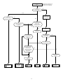
1
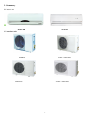
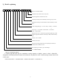
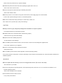
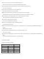
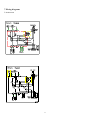
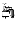
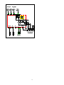
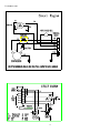
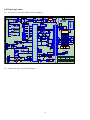
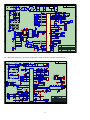
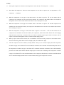
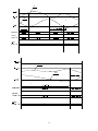
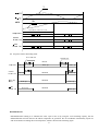
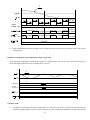
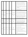
Service manual
Room airconditioner
Split Wall-Mounted Type
NOTE:
Before servicing the unit, please read this first
Always contact with your service center if meet
problem.
1
Table of Contents
1、Summary ………………………………………………………………………………………………………………3
2、Model explaining …………………………………………………………………………………………………….4
3、Installation……………………………………………………………………………………………………………..4
4、Exploded view and part list………………………………………………………………………………………..8
5、Operation principle………………………………………………………………………………………………….9
6、Specifications…………………………………………………………………………………………………………10
7、Wiring diagrams……………………………………………………………………………………………………...11
8、PCB principle chart……………………………………………………………………………………………….....16
9、PCB function …………………………………………………………………………………......17
10、Troubleshooting………………………………………………………………………………....33
2
1. Summary
1.1 indoor unit
Model 38B
model 85
1.2 outdoor unit
9000BTU
12000~18000 BTU
22000 BTU
24000~26000 BTU
3
2、Model explaining
c
Improve an ordinal number
Divide the body outdoors box a body code
External appearance characteristic code
Separately the body indoor machine(or whole type) style code
Separately the body pit code inside the indoor machine(or whole
type)
Code of refrigerant type:no code - R22;C-R407c、A-R410a
Power type:1:115v/60Hz 2:220V/60Hz;3:220-240V/
50Hz;4:240V/50Hz;
Main function code: c-Cold breeze type;H-Hot pump type;A-Hot
pump the type take assistance electricity to heat;E-The electricity
heat
Capacity code: x1000W
Structure form code
Special craft code:Q-Deal with contact quickly;S-Soft start;dOutside tube in addition to frost
The weather type code(T1 type code abridge)
"C" CHIGO brand
Such as: CS-25C3A-V85AY1
T1 climate type,wall split type air conditioner, cooling capacity is 2500W,power is 220V~/50Hz/1PH,
refrigeration is R410A,the kernel of indoor unit is fresh 98,the pattern no. is 85,first time design, outdoor unit is 1HP
of 2003 year。
Indoor unit modle is:CS-25C3A-V85A,outdoor unit model is:CS-25C3A-Y1。
4
3. Attention of installation
3.1 Safety Precaution
■To prevent injury to the user or other people and property damage, the following instructions must be followed.
■Incorrect operation due to ignoring instruction will cause harm or damage.
■Before service unit, be sure to read this service manual at first.
3.2 Warning
﹥Installation
■Do not use a defective or underrated circuit breaker. Use this appliance on a dedicated circuit.
There is risk of fire or electric shock.
■For electrical work, contact the dealer, seller, a qualified electrician, or an Authorized service center.
Do not disassemble or repair the product, there is risk of fire or electric shock.
■Always ground the product.
There is risk of fire or electric shock.
■Install the panel and the cover of control box securely.
There is risk of fire of electric shock.
■Always install a dedicated circuit and breaker.
Improper wiring or installation may cause fore or electric shock.
■Use the correctly rated breaker of fuse.
There is risk of fire or electric shock.
■Do not modify or extend the power cable.
There is risk of fire or electric shock.
■Do not install, remove, or reinstall the unit by yourself (customer).
There is risk of fire, electric shock, explosion, or injury.
■Be caution when unpacking and installing the product.
Sharp edges could cause injury, be especially careful of the case edges and the fins on the condenser and evaporator.
■
For installation, always contact the dealer or an Authorized service center.
There is risk of fire, electric shock, explosion, or injury.
■Do not install the product on a defective installation stand.
It may cause injury, accident, or damage to the product.
5
■Be sure the installation area does not deteriorate with age.
If the base collapses, the air conditioner could fall with it, causing property damage, product failure, and personal injury.
■Do not let the air conditioner run for a long time when the humidity is very high and a door or a windows is left open.
Moisture may condense and wet or damage furniture.
■Take care to ensure that power cable could not be pulled out or damaged during operation.
There is risk of fire or electric shock.
■
Do not place anything on the power cable.
There is risk of fire or electric shock.
■Do not plug or unplug the power supply plug during operation.
There is risk of fire or electric shock.
■Do not touch (operation) the product with wet hands.
There is risk of fire or electric shock.
■Do not place a heater or other appliance near the power cable.
There is risk of fire and electric shock.
■Do not allow water to run into electric parts.
It may cause fire, failure of the product, or electric shock.
■Do not store or use flammable gas or combustible near the product.
There is risk of fire or failure of product.
■
Do not use the product in a tightly closed space for a long time.
Oxygen deficiency could occur.
■When flammable gas leaks, turn off the gas and open a window for ventilation before turn the product on.
Do not use the telephone or turn switches on or off. There is risk of explosion or fire.
■If strange sounds, or small or smoke comes from product. Turn the breaker off or disconnect the power supply cable.
There is risk of electric shock or fire.
■Stop operation and close the window in storm or hurricane. If possible, remove the product from the window before the hurricane
arrives.
There is risk of property damage, failure of product, or electric shock.
■Do not open the inlet grill of the product during operation. (Do not touch the electrostatic filter, if the unit is so equipped.)
There is risk of physical injury, electric shock, or product failure.
■When the product is soaked (flooded or submerged), contact an Authorized service center.
There is risk of fire or electric shock.
■Be caution that water could not enter the product.
6
There is risk of fire, electric shock, or product damage.
■Ventilate the product from time to time when operating it together with a stove, etc.
There is risk of fire or electric shock.
■Turn the main power off when cleaning or maintaining the product.
There is risk of electric shock.
■When the product is not be used for a long time, disconnect the power supply plug or turn off the breaker.
There is risk of product damage or failure, or unintended operation.
■Take care to ensure that nobody could step on or fall onto the outdoor unit.
This could result in personal injury and product damage.
﹥CAUTION
■Always check for gas (refrigerant) leakage after installation or repair of product.
Low refrigerant levels may cause failure of product.
■Install the drain hose to ensure that water is drained away properly.
A bad connection may cause water leakage.
■Keep level even when installing the product.
To avoid vibration of water leakage.
■Do not install the product where the noise or hot air from the outdoor unit could damage the neighborhoods.
It may cause a problem for your neighbors.
■Use two or more people to lift and transport the product.
Avoid personal injury.
■Do not install the product where it will be exposed to sea wind (salt spray) directly.
It may cause corrosion on the product. Corrosion, particularly on the condenser and evaporator fins, could cause product malfunction or
inefficient operation.
﹥Operational
■Do not expose the skin directly to cool air for long periods of time. (Do not sit in the draft).
This could harm to your health.
■
Do not use the product for special purposes, such as preserving foods, works of art, etc. It is a consumer air conditioner, not a
precision refrigerant system.
There is risk of damage or loss of property.
■
Do not block the inlet or outlet of air flow.
It may cause product failure.
7
■Use a soft cloth to clean. Do not use harsh detergents, solvents, etc.
There is risk of fire, electric shock, or damage to the plastic parts of the product.
■
Do not touch the metal parts of the product when removing the air filter. They are very sharp.
There is risk of personal injury.
■
Do not step on pr put anything on the product. (outdoor units)
There is risk of personal injury and failure of product.
■Always insert the filter securely. Clean the filter every two weeks or more often if necessary.
A dirty filter reduces the efficiency of the air conditioner and could cause product malfunction or damage.
■Do not insert hands or other object through air inlet or outlet while the product is operated.
There are sharp and moving parts that could cause personal injury.
■
Do not drink the water drained from the product.
It is not sanitary could cause serious health issues.
■Use a firm stool or ladder when cleaning or maintaining the product.
Be careful and avoid personal injury.
■Replace the all batteries in the remote control with new ones of the same type. Do not mix old and mew batteries or different types of
batteries.
There is risk of fire or explosion.
■
Do not recharge or disassemble the batteries. Do not dispose of batteries in a fire.
They may burn of explode.
■
If the liquid from the batteries gets onto your skin or clothes, wash it well with clean water. Do not use the remote of the batteries have
leaked.
The chemical in batteries could cause burns or other health hazards.
3.3 Installation details
■
Wrench torque sheet for installation
Outside diameter
Torque
mm
inch
Kg.m
φ6.35
1/4
1.8
φ9.52
3/8
4.2
φ12.7
1/2
5.5
φ15.88
5/8
6.6
φ19.05
3/4
6.6
8
■Connecting the cables
The power cord of connect should be selected according to the following specifications sheet.
Grade
Unit
7K
9K
12K
18K
24K
28K
mm2
1.0
1.0
1.5
2.5
2.5
2.5
■ Pipe length and the elevation
Standard length
Capacity
Max.
Max.
Additional
Elevation
Elevation
refrigerant
B (m)
A (m)
(g/m)
Pipe size
(m)
Btu/h
GAS
LIQUID
9K-12K
3/8’’ (φ9.52)
1/4’’ (φ6.35)
3.5
5
10
30
18K-22K
1/2’’ (φ12.7)
1/4’’ (φ6.35)
4
10
15
30
24K-28K
5/8’’ (φ15.88)
3/8’’ (φ9.52)
5
15
20
65
Caution:Capacity is base on standard length and maximum allowance length is base of reliability.Oil
trap should be install per 5-7 meters.
4、Indoor unit and outdoor unit explosion diagram and spare parts list(see explosion diagram file)
5. Refrigerant cycle diagram
5.1 Cooling only
9
5.2 Heat pump mode
6. Specifications (see spec sheet)
10
7.Wiring diagrams
7.1Indoor unit
11
12
13
14
7.2 Outdoor unit
15
8.PCB principle chart
8.1、38 section of crystal color ordinary schematic diagram
3
4
B
E1
C13
10 4
8
P07
30
20
X3A
13
4
P32
GND
P33
C15
10 2
HSTP.0
B
16
电加热
26
P12
D11
GND
41 48
外风 机
X4A
FM O
15
外风 机
2
52 X4B
P11
Q 5 制热
5
DATA
GND
4
D7
41 48
IC1
R8
4. 7 K
R9
4. 7 K
74 AL S1 64
电 加 热 /无
HSTP.1
32
R13
IN41 48
18 15
4. 7 K
4. 7 K
R7
B
L1
C24
U2
GND
GND
8
R6
4. 7 K
P00
+5
2
Q7
18 15
GND
13
P34
1
XL
8. 0 0
R20
4. 3 K
C8
10 4
GND
GND
3
R17
51 0
P20/AN0
R18
4. 3 k
Vss
C6
10 4
15
3
4. 7 K
R22
GND
P14
R21
C18
10 1
14
10 K
4. 7 K
GND
C10
10 2
+5
GND
INT0
16
R4
10 K
10 K
产品 名称
AC..ZERO
R2
设
计
绘
图
5
GND
GND
6
8.2、65 Mitsubishi main chip schematic diagram
16
22 UF/1 6V
(37544)38款晶彩普通电 控 原 理 图
审
A
核
姚贤 清
批 准
杜娟
日 期
4. 7 K
标准 化
Q1
C18 15
10 2
4
E1
1
GND
10 2
C5
HS 0 0 3 8
R1 51
GND
C11
GND
3
GND
C19
10 4
R3
22
GND
3
2
1
2
GND CNW
R5
4. 7 K
4
GND
2
+5
风机 反馈
5
P37
GND
B
LED
DPY-8 *2
dp
RMT
S
1 GN D
3 +5 V
CNTR0
Xin
f
b
c
d
S
3
R24 10 K
R23
P30
2
CN D
+5
+5V
30 0K
Tp 管
GND
11
R15
P21/AN1
GND
GND
10 uf/1 6F
4. 7 K
C12
10 2
51 0
CO M2
GND
-+
R19
a
a
g
e
10 4
GND
17
Xout
GND
h
f
dp
接收头
R35
12
+5
g
b
c
d
21
C14
10 2
/RESET
g
e
E5
51 0
R38
10 K
7
10
SW 1
GND
b
a
2
Vcc
C4
R16
10 K
GND
R25
R39
10 K
c
f
6
应急 键
d
R31
4. 7 K
Q8
9012
2
e
COM2
P22
+5
E8
1u F/5 0V
C7
10 4
6
1
MC3 02 1
C9
10 4
23
com2
R37 33 0
R34
2K
4
CO M3
com1
4
+5
1
6
Q5
90 12
R11
P24
L E D5
R30
4. 7 K
R14
39 0
IC5
3
CNG
TEMP
3
D2
L E D3
4. 7 K
3
2 BCR
R36
22 0
+5
10 2
+5
IC6
L E D4
L E D7
COM3
3
1
D1
4. 7 K
2
C20
47 3/2 75 V
L E D6
4. 7 K
Q6
90 12
R12
P25
24
1
N
改为 跳 线 , 保 留 孔 位
CFI
1. 2 uF
1
9
BUZZ
P01
1
R32
S
C23
10 4/2 75 V
L E D2
CO M1
L E D1
COM1
+5
Q2
2K
CNU
Q4
90 12
P02 25
90 13
GND
R5
8
D6
R33
+5
4. 7 K
52 CB
Q3
R6
压机
BZ
41 48
D8
R10
GND
C
R9
D10 41 48
41 48
R2
D12
8
7 P23
R8
P13
51 0* 8
R4
2
+5
TYPE1.1
dhon/off
31
14
41 48
R3
P10
3
52 X5B
JZC-7F*2
Tr 室
102
+5
TYPE1.0
heat/cool
D9
Q 3 通风
102
R7
14
换向阀
A
51
C16
10 2
FM C
B
R26
CLOCK
3
1
51
单 冷 / 双温
P03
1
52 X6B
R27
C2
9
4
19
P31
C3
8
29
C28
10 2
Q7
P06
Q 4 除湿
DA T A
7
5
Q 2 制冷
CL OC K
MR
28
5
Q6
12
3
步进电机
5
4
GND
Q 5 CL K
CN M
U1
C
AT 2 4 C0 2
4
13
P05
6
18
20 S
7
R28 4. 7 K
D
Q 7经 济 F
R11
10 K
12
11
电加热
四通阀
3
5
R12
10 K
R29 4. 7 K
2
52 X6A
6
CN1
1
+5
27
IC7
Q 1强 力 D
Vss
P04
7
GND
CN
2
MC2 00 3
10
1
10 4
1
A
Q 0 定时 E
Q4
9
C17
火线
七灯显 示 板
Q 6 运行
GND
+5
11
52 C-1A
配灵通3号遥控器
22 0UF/16V
+5
E4
22 UF/2 5F
2
CN
10 00 UF/35 V
JS2-B38aC-M15A/0
E3
C3
10 4
A
COM
CM
+5
3
OUT
CN4T
B
5
压机
Vin
C2
10 4
B
U2
JL C03 01
IN40 01
变压器
L2
U1
变压初级
火线 由 压 机 的 COM 端进 入
E2
C1
10 4 22 0UF/35V
Q3
1 0A
FUSE
F3 A 25 0V
1
D5
Q2
火线
51 /1W
D1-D4
C22
10 4/2 75
Q1
47 1
U
D
R1
AC.ZERO
T
JL C03 01
C21
10 4/2 75 V
6
10
L3
ZR
8
编号
5
零线
7
78 05
Q0
N
6
IC4
4
CNB
N1
5
变 压 器 次级
G ND
2
2
1
佛山市中格威电
7
子有限公 司
8
2
3
FU S E
火线
4
5
L1
FU S E +ZR
6
B
1 0 A- 1 8 0 - 6 2 1
R1
1
T1
CNC
8
编号
+5
Vin
51 /2W
CNB
2 5 0 V/3 .1 5 A
7
IC 6
7805
3
Vout
G ND
1
JS2-B65aC-M11A/0
E1
D1 -D 4
D
5 2 CB
1 10
低风
CN U
7
8
C2 2
1 0 0 /1 W
P3 0
E3
1 0 0 UF/2 5 V
GND
11
0 .1 u f/27 5 V
IC 2 F
18
6
CFO
4
高风
电 容
3 .5 UF/50 0 V
低风
X3 B
中风
X4 B
高风
X5 B
IC 2 E
12
P3 1
19
5
X2 A
P0 3
4
20
IC 3
2003
1
4. 7 K R13
26
10 3
C10
P3 3
16
IN 2 OUT 2
15
3
IN 3 OUT 3
14
4
IN 4 OUT 4
13
5
IN 5 OUT 5
12
6
IN 6 OUT 6
11
7
IN 7 OUT 7
10
8
COMCLAMP
9
X1 A
外风
IC 2 C
X2 B
机 FMO
2 14
换向 阀
X1 B
20S
5 2 X6 A
R1 6
9
NC
1
E1 0
DA 2
IN 4 1 4 8
DA 3
IN 4 1 4 8
DA 4
IN 4 1 4 8
DA 5
IN 4 1 4 8
DA 6
IN 4 1 4 8
*
R1 0
R8
4 .7 K
4 .7 K
R1 1
R9
4 .7 K
1
P1 0
4 .7 K
R7
+5
GND
R6
10K
P 11
3
4 .7 K
A
单冷
有
室外传感器化霜
双温
双温有电加热
外板化霜
数码管显示
DA 3
DA 4
AR 5
39 0Ω
R5
R4
6
4. 7 K
4. 7 K
7
R28
R29
8
IC 8
+5V
GND
COM 1
P2 3 / AN3
C7
10 2
90 12
COM 2
COM 1
P2 1
Q4
COM 2
GND1 0 0 UF/2 5 V
30
Vs s
P0 7
C1 9
104
SW1
GND
AR 5
金膜
E 10
22 UF/2 5V
(37544)诚 丰 65款主控/ 电 源板 原 理 图
产品 名称
可调 电 阻
GND
C2 0
104
GND
GND
16
Vr e f 1 0
4. 7 K
10 2
C9
90 12
C22
10 4
设
计
张建
绘
图
范丽英
4
批 准
日 期
佛山市中格威电
GND
3
5
A
核
审
标准 化
M3 7 5 4 4 G2 ASP
+5
CN1
2
GND
R2
R2 4
10K
GND
E8
1 0 0 u f/25 V
10 2
C8
FE E D
外反 馈
7
13
Vc c
5
B
化霜
R2 3
+5
C4
+5
90 12
E4
1
R2 5 4 .7 k
R12GND
+5V
A0
*
Q3
C6
102
A1
VCC
1 0 0 u f/25 V 1 0* 4
P2 0
4. 7 K
DATA
WP
2
2 4 C0 2
R M T _IN
CLK
4
GND
3
SCL
4
DE FR OS T E R
2 0 0 K/2 W
D6
IN 4 0 0 7
C1 8
A2
SDA GND
E5
R3
4. 7 K
+5V
COM 3
1
5
31
Q2
39 0Ω
双温无电加热
智能化霜
灯板显示
化霜参数调节(请参看说明书)
DA 2
P1 4
32
103
+5V
C5
102
P 10
GND
DA 1
P1 1
P1 3
L
R2 2
2 0 0 K/2 W
D5
IN 4 0 0 7
IC 5
+5
P1 2
2
GND
104
AA
25 v
GND
10K
R2 6
4 .7 K
T YPE _ IN2
104
IC 4
R2 1
P0 6 2 9
金膜
C1 7
103
RE SE T
T YPE _ IN1
C2 3
E7
1 0 UF
GND
10K
R2 7
TR t。
室温
+5V
4 .7 K
R3 1 5 1 0 Ω
10K
GND
无
无
P2 2 / AN2 6
11
R3 4
R3 2
10K
P20
B
DA 1
IN 4 1 4 8
金膜
R1 9
4 .3 K C2 1
C1 6
104
R20
Q1
90 12
CN1 2 0
P21
R3 5
4 .7 K
t。
TP
管温
GND
4 .7 K
GND
AA
4 .7 u F/5 0 v
DA 5
R1 8
C1 5
104
R3 3
2K
8
P07
CN G1
R1 7
4 .3 K
C1 4
104
8
P0 0
CO M
5 2 CA
二极管
P2 4 / AN4
23
+5
C
104
+5
4 .7 K
C1 3
104
GND
7 16
压机
GND
C2 4
P3 7
IC 2 A
5 2 X6 B
电 加 热
R3 6
4 .3 K
GND
22
2
+5
BZ
R14
C1 2 1 0 4
GND
P2 5 / AN5
6 15
电加 热
B
CN M2
2 2 UF/25 V
P3 4
IC 2 B
换 向 阀
CNG2
CN M1
E6
R3 7
4 .7 K
*
21
3
T P2
管温 2
2K
CNVs s 1 2 GND
C
+12
IN 1 OUT 1
2
P3 2
IC 2 D
3 13
外风 机
步 进 电 机
GND
P0 5 2 8
27
P0 4
25
P0 2
24
P0 1
X5 A
电 容
R3 0
3 0 0 K XL 1
8M
15
Xo ut
6
中风
零线
17
C3
104
X4 A
R2 5
14
Xi n
B
CN
负离 子
GND
I C1
IC 2 G
X3 A
火线
t。
B
2003
CN 1
S2
4 7 0 u F/3 5 V
金膜
0 .1 UF/27 5 V
零线
C2
104
2 2 0 UF/2 5 V
40 07
9
D
E2
2
C1
104
C2 1
S1
6
子有限公 司
7
8
8.3、85 section of schematic diagrams
1
2
3
零线
1
2
4
3
变压 器
初
1
E1
10 00 UF/35 V
IN 4 0 0 7
D1 --D 4
次级
级
4 7 3 / 2 75 V
2K
C1
9
净化
R2
CNL
C30
10 4
E9
22 UF/1 6V
GND
X1A
换向 阀
CNG
T MP86 F80 9NG
30
CLAMPCOM
8
OUT 7 IN 7
7
11
OUT 6 IN 6
6
12
OUT 5 IN 5
5
15
13
4
16
OUT 4 IN 4
IW
U1
B
E2
22 0UF/25V
GND
C32
31
10 2
R47 4. 7 k
R27 10 K
X2A
电加 热
5 2 X4 A
F MO
外风 机
+5V
压机
L3
C3
N1
IC4
CF I
1 . 2 UF / 4 5 0 VAC
MF1
1
R1
220
内风 机
4
1
6
2
BT 13 1
IW
24
C20
C21
104
104
VD D 5
IC2
14
3
18
OUT 3 IN 3
15
2
25
OUT 2 IN 2
R3 0
10 4
4 .3 K
4 .3 K
10 4 C16
16
OUT 1 IN 1
GND
R32
P1 1
R25 4. 7 k
+5
7
10 2
19
C24
10 2
R9
20
GND
21
C9
10 2
10 4
R19
GND
5
+5
10 2
10 2
10 2
11
C33
12
CNE
10 4
R14
E9
C22
+5
+5
4
IC5
24 C02
8
A1
WP
7
SCL
6
A2
10 2
C29
GND SDA
4148
4148
D9
GND
D7
4148
4148
GND
R11
+5
GND
GND
R6
1
2
+5V
管温2
B
强制 按键
GND
5
R7
GND
C8
10 2
1 6 VC C
1 0 S CL R
9 Q H*
51
R5
4. 7 K
C10
10 2
G ND
GND
+5
CL OC K1 4 S I
DA T A 1 1 S CK
13 G
8
GN D
E5
QH 7
QG 6
QF 5
QE 4
QD 3
QC 2
QB 1
Q A 15
G ND
4 7 UF/25 V
M7 4 H5 9 5
3
4. 7k
10 4
IC16
16
15
14
13
12
11
10
9
IN 1OUT 1
IN 2OUT 2
IN 3OUT 3
IN 4OUT 4
IN 5OUT 5
IN 6OUT 6
IN 7OUT 7
COM
CLAMP
SW1
C7
10 2
GND
GND
GND
+5
RC K
+5
1
2
3
4
5
6
7
8
20 03
IC 1 3
12
51
Q1
90 13
2
10 K R41 R38 R35 R34
R4
4. 7 K
R12
4. 7 k* 2
C6
B
R39 R40 R37 R36
4148
10 2
A
1
R1 3
10k
R2 4
4. 7 K
R4 5
+5
VCC
4148
D1 1
C28
4 .7 k
+5V
A0
D8
D1 0
R2 9
4 .3 K
10 4
C18
10 4
10 k* 5
R4 4
4 .7 k
1 0 0 uF/ 2 5 V
E6
D1 2
+5
22 UF/1 6V
3
R17 R16
CNP
+5V
GND
GND
2
9
13
10 4
GND
1
R15 R18
GND
R28 10 K
32
1
C36
E 7 4 .7 UF/50 V
RE S E T 8
10
C11
IN 4 1 4 8
D6
28
R23
C12
GND
GND
R4 3
10K
R22
4
2
+5
2
29
22 0* 3
6
B
XI N
XL
C14
10 2
Z
R8
4. 7 K
10 3
RX
8M
30 0K
26
22 0 R20
C37
10 K
C27
XO UT 3
27
C
GND
Q2
18 15
C26 10 2
R21 22 0
C13
GND
GND
R42 10 K
P1 0 2 2
C34
1
C15
10 2
R10
4. 7 K
+5
2
10 2
GND
CNM
3
10 k
GND
23
14
1
+5
GND
C19
E 3 1 0 0 UF/2 5 V
GND
+5
10 0UF/25V
TE ST 4
GND
4 7 3 / 2 75 V
3
+5V
R3 1
C17
E8
C31
10 4
6
R4 6
390
C3 5
52 CA
B
R3
330
1 0 4 / 2 75 V
5
C
52 X6A
U1
X5B
室温
17
P1 2
VS S 1
FMC
管温
R26 10 K
GND GND
H F 2 16 0-1A -1 2D E
外风 机
220
5 2 X5 A
20S
JS2-B85aC-T01A/0
3
20 03
IC14
10
电加 热
四通阀
OUT
IC1
R3 3
U
COM
B
Vin
C25
10 4
10 4
C23
B
BZ
COM
B
9 5 3 -1 A
5 2 X6
HE AT NO
X 5B
CN A
U
火线
X5A
5 2 C (12 V )
NO
8
编号
D
负离子
CM
7
+5
7805
U1
S1
压机
6
IC 5
IN 4 0 0 7
10 4/2 75 V
10 4/2 75 V EF - 1 0 05 GS1
2
1
CN C
T RANS
C2
C1
S
B
D5
G ND
ZR
CN1
5
Z
CN B
L
FUSE
D
4
U1
62 1-1 0-12 6
2
3. 1 5A 2 50V
火线 U
1
2
3
4
5
6
7
8
IC15 20 03
IN 1OUT 1
IN 2OUT 2
IN 3OUT 3
IN 4OUT 4
IN 5OUT 5
IN 6OUT 6
IN 7OUT 7
COM
CLAMP
16
15
14
13
12
11
10
9
CNM2
B
E4
CNM1
B
CNM
产品 名称
M70 内核东 芝 809 芯片85款(简易 三 灯 )
电 控 原理 图
计
审
绘
图
批 准
B
日 期
标准 化
B
1 0 0 UF/2 5 V
C5
GND
4
10 4
佛山市中格威电
5
6
A
核
设
7
子有限公 司
8
8.4、Three water chestnut 18NV 85 section of entire compatible electrically controlled schematic diagrams
17
1
2
3
4
5
6
7
B
U1
L
Vin
4
3
1
2
D1 - D4
4001
C1 2
1 0 4 / 2 75
AC- N
编号
3
OUT
JS2-B85AC-M01A/0
GN D
L1
火线 由 压 机 的 ON端引人
8
+5
1
安规 电 容
E1
C1
I C4
7805
C2
10 4
E1
E3
2
F USE+ ZR
F USE
C3
104
4 7 0 UF / 2 5 V
T RANS
1 0 0 0 UF/ 3 5 V
1 0 4 4 7 0 UF / 5 0 V
零线
D
D
N
HI
IC1
U1
X3 B
B
GND
C5
IC1
X4 B
MI D
I C4C 9
B
MF1
低风
X5 B
中风
X4 B
P07
14
R9
30
220
4148
D6
4 .7 K
P10
8 P2 4 / AN
3
高风
R1 0 2 2 0
31
4148
D7
D9
13
52 X6 B
X2 B
X1 B
换向阀
外风 机
2
X2 B
15
20 03
1
电加热
COM
52 X6 B
I C3B
L
压机
3
52 CB
16
火线
CN
UL 20 03
52 CB
COM
压机
火线
+5 V
CM
CN
C4
9
10
11
12
13
14
15
16
2
步
进
3
电
VC C
GND
QH 7
QG 6
10 4
机
9
10
11
12
13
14
15
16
1
CNM
GND
G
3
电
4
C2 2
C2 4
10 2
10 2
10 2
17
51
R4 7
51
P0 3
27
P0 4
P1 2
1
P1 1
32
1
GND
R11
4. 3 K
P2 1 / AN
R1 5
5
C10
10 2
+5
39 0
R1 2
4. 3K
GND
+5 V
P2 0 / AN
室温
28
P0 5
IC4F
6
2
P1 3
IC4E
3
5
20 03
B
。
t
3
铜头
R1 3
4. 3K
C1 1
10 4
R7 22 0
CNG 管温
C9
10 4
GND
IC5
+5
A T2 4C 0 2
R 40
R 39
4.7K
4.7K
8
P1 4 / CNTR0
1
2
6
3
E8
4.7u f/2 5F
7
4
5
GND
8
GND
E7
+5 V
GND
E 10
R44
2K
30 0K
14
1
R45
10 K
E6
2 2 SDA
R 3 51 0
Xi n
Vr e f
10
Vc c
13
+5 V
1 1 / RES ET
C1 2
22 uf / 2 5V
CN1 6 1
R46
10 K
GND
4. 7K
R2
Vs s
1 2 CNVs s
16
三菱(37544)18NV P型板85款全兼容电控原理图
产品 名称
R4 1
8. 00
GND
90 12
2 1 SCL
P3 7
XL
Q7
1u F/50 V
B
P3 4
1 5 Xo ut
10 0u F/25V
R6 10 0
1 泪滴
C8
10 4
R1 4
4
4 7 UF/16 V
12
5
。
t
2
C1 0
10 4
+5
机
10 4
E9
管温2
C7
10 4
4
E4
11
R5
C2 0
2
1
4. 7 K
GND 22 Uf / 5 0V
R8 4.7K
2K
CNG2
R4
6
GND
GND
BZ
E5
10 4
计
审
绘
图
批 准
10 uf / 1 6v
日 期
标准 化
GND
GND
佛山市中格威电
GND
2
3
4
5
6
7
2
3
4
5
CN B
IN 4 0 0 7
变压器
FU S E
F3 .1 5 A 2 5 0 V AC
火线 由 压 机 的 COM 端进 入
U1
变压初级
IN 4 0 0 7
CN
5 2 C-1 A
C2 2
102
P11
32
26
4 .7 K
D8
P03
5 2 X6 A
P12
1
P13
2
25 P02
D1 5
B
31 P10
M C 20 03
B
X1 A
四通阀
X2 B
电加热
5 2 X6 B
P24
5
13
L1
压机
5 2 CB
外风机
X1 B
11
R2 6
220
1
C1
4 7 3 /2 75 V
1
1
P00 23
6
P23
7
P32
4
IC 4
+5
17
18
P01
2
P3 0
P3 1
10K
R19
10K
28 P05
24
2
1
GND
C2 4
104
Xout
P20
10K
P21
3
+5
4
C2 6
104
R3 2
4 .3 k
GND
Q1
R2 0 2 K
AC..ZERO
R3 0
10K
C1 1 1 0 K
102
C2 5
103
2
+5
+5
R2 1
4 .3 K
+5
C23
10 4
QD
QE
QF
1
2
3
4
5
IC2
7 QH
6
8
10
SCLR
RCK
R38
4. 7 K
QG
M74HC595
1
2
C5
16
VCC
B
G
90 13 Q4
13 GND
GND
+5
104
XH-2A
GND
GND
90 13 Q2
GND
10 VRE F
GND
C1 7
104
15
+5
E1
1 0 0 u F/1 6 V
R4
10K
4
5
29
P06
GND
R1 6
4 .7 K
S
P37
C1 8
102
产品 名称
+5
22
R3
10K
C1 0
102
3
16
Vss
CNW
+5
R3 1 4 .7 K
CNTR0
P14
C1 3
102
风机 反馈
GND
4
E2
GND
5
计
绘
图
小分体电控原 理图( 0C314芯片)
C2 9
104
陈
斐
审
A
核
批 准
日 期
标准 化
佛山市中格威电
6
18
设
10 0μF/2 5V
GND
3
QC
12
R7
4. 7 K
CN1
R2 9 1 0 K
INT10
GND
GND
GND
11
S1 14
4. 7 K
GND
R2
C1 8 1 5
SCK 1 5
R13
R2 7
10K
GND
GND
GND
1
C2 0
104
R5
QB
13 Vcc
RX
300K
+5
GND
R1 4
R22
10 0
47 1
104
C1 9
14
10 0
C28
11 /RESET
Xin
XL
8 .0 0
GND
47 1
GND
Q3
9012
10K
E6
47 UF/2 5V
GND
C27
C7
2K
E3
GND
7
4
CLK
DATA
6 P22
104
510
5
4
3
2
1
B
E5
4 7 u f/2 5V
3
QA
GND
GND
R3 3
1uf/50V
C2 1
104
2
IC7 AT 2 4 C0 2
27 P04
R23
GND
1
5
15
R3 4
R36
+5
R1
R1 7
4 .3 K
8
R3 7 4 .7 K
6
P07 30
7
2K
TEMP
GND
CNM1
B
R1 8 4 .7 K
10
C
步 进 电 机内 风 门
+5
2
5
4
3
2
1
B
D1 6
GND
GND
A
步 进 电 机外 风 门
C16
10 2
GND
1
GND
C1 4
104
COM
CLAMP
IN 7OUT 7
IN 6OUT 6
IN 5OUT 5
IN 4OUT 4
IN 3OUT 3
IN 2OUT 2
IN 1OUT 1
R3 5 4 .7 K
R2 4
390
BC R
B
Tp 管
C12
10 2
C8
10 2
CNM
9
10
11
12
13
14
15
16
20 03
R1 0 2 2 0
IC1
0C314
IC5
4148
BZ
+5
QA
QB
QC
QD
QE
QF
QG
1
2
3
4
5
6
8
7
6
5
4
3
2
1
IC 9
B
Tr 室
CNE
XH-6A
+5
S
GND
R6 2 2 0
MC3 0 2 1
CNG
GND
DI
20 P33
12 CNVSS
R2 5 3 3 0 6
3
B
C15
4148
D9
R1 1 2 2 0
U1
3
2
D1 4 4 1 4 8
4148
WR
+5
CFI
1 .2 u F
TYPE1.1
dhon/off
3
N
5
16
C2
1 0 4 /2 75 V
电 加 热 /无
CS
21 P34
P25 9
4
D1 3 4 1 4 8
D1 2 4 1 4 8
10 4
19
外风机
D7
R9
R8
4 .7 K 4 .7 K
8
FM C
CNU
4148
9
GND
IC3 12
+5
TYPE1.0
heat/cool
E4
4 7 u F/2 5 V
四通阀
GND
R1 2
4 .7 K
D1 0 4 1 4 8
单 冷 / 双温
HSTP.1
C9 1 0 4
X2 A
FM O
D1 1 4 1 4 8
4148
HSTP.0
GND
C
E1 1
2 2 0 UF/2 5 V
D
GND S W 1
U1
JS2-B85aC-M01A/2
104
+5
R2 8
火线
8
编号
C6
R1 5
10K
H E AT
20 S
OUT
+5
应急 键
电加热
C4
104
E1 0
1 0 0 0 UF/3 5 V
变压器次级
COM
CM
压机
Vin
AC.ZERO
D1 2
D1 -D 4
2
D
T
3
2
ZR 6 2 1 -1 0-1 2 6
火线
L
7
+5
IC 8 7 8 0 5
1
1
零线
N
6
B
CN C
C3
1 0 4 /2 75 V AC
G ND
1
7
子有限公 司
8
8.5、Mitsubishi Jin dynasty 85 model of simple three lamp electrically controlled motherboards
N1
A
核
设
GND
1
C
2
GND
C8
10 2
HS 0 0 3 8
2 2 UF/16 V
3
P3 0
26
51
+5 V
SW1
GND
A 10 15
Q3
R1
C N 13 3
R2 2
10 k
强制按键
R4 6
3
2
1
E2
1 +5 V
1
RMT
S
3 GN D
GND
R2 3
10 k
+1 2V
20 03
6
S CN 1 2 3
C2 3
+5
8
M7 4 H5 9 5
8
7
6
5
4
3
2
1
AJ1
进
2
Q6
90 13
R45
4. 7 K
13
GN D
BB 5
BB
39 0
CLAM COM
P
OUT 7 IN 7
OUT 6 IN 6
OUT 5 IN 5
OUT 4 IN 4
OUT 3 IN 3
OUT 2 IN 2
OUT 1 IN 1
2
步
R36
P2 2 / AN
16
IC7
E7
22 uf / 2 5V
10 0
C6
10 4
S CL R 1 0
5
4
Q H* 9
3
2
1
14
15
CL OC K S I
DA T A S CK 1 1
QF
QE
QD
QC
QB
QA
B
B
25
AA
2
R44
4. 7 K
8
7
6
5
4
3
2
1
20 03 C5
5
P02
+5 V
CLAM COM
P
OUT 7 IN 7
OUT 6 IN 6
OUT 5 IN 5
OUT 4 IN 4
OUT 3 IN 3
OUT 2 IN 2
OUT 1 IN 1
4
R35
RC K 1 2
IC6
C N -AC
A
P3 1
10 0
+5 V
GND
10 4
B
B
18
24
IC 3
CN12
负离子
P3 2
20 03
I C3C
EF AN
HEAT
P3 3
19
23
P01
- +
FM C
20
3
P00
AA 4
ST B
14
X1 B
C
4
I C3D
外风 机
P23
R34
10 0
20 03
CNH
M37544G2SP
换向阀
7
4
20 03
I C3E
电加热
R3 2
D1 1 4 1 4 8
4148
4 .7 K
13
X3 B
CF I
VALVE
+5
R3 3
D1 0 4 1 4 8
9 P2 5 / AN
20 03
I C4E
CF
4148
D8
GND
20 03
I C4D
X5 B
LO
10 4
2
15
子有限公 司
8
9. PCB function:
NOTE: Ts is the set temperature, Tr is indoor room temperature, TP1 is indoor coil pipe temperature, TP2 is outdoor
coil pipe temperature.
Display panel
[1]only two LED
①running lamp(green):power on light, flash one time/ one second during anti cooled wind.
②timer lamp(yellow):only light at timer state.
[2]eleven LED
① running lamp(green):power on light, flash one time/ one second during anti cooled wind.
②temperature lamp(green):16~31℃ set temp. and room temp. display, light is set temp. flash is set temp.
[3]two LED and two 8LED
running
timer
① running lamp(green):power on light, flash one time/ one second during anti cooled wind.
② timer lamp(yellow):only light at timer state.
③8LED display set temp., also it can display timer time and failure code.
[4]LED multi-colour panel
①according to display mode: dehumidification, cooling, ventilation, heating, auto, sleep, fan speed, swing, timer, indoor
fan running.
19
Cooling
●
Start up the compressor: when the room temperature is more than Ts+1℃, compressor → start-up
●
Shut down the compressor: when the room temperature is less than or equal to the set temperature Ts-1℃,
compressor → shutdown
●
When the temperature of coil pipe of the indoor units is less than or equal to 1℃ for one minute and the
compressor has continuous run for more than ten minutes, the compressor and outdoor blower fan shut down
through the electric control board and the indoor blower fan is running at low speed.
●
When the temperature of coil pipe of the indoor units is more than or equal to 7℃ and the compressor has
shutdown for more than three minutes, the compressor and outdoor blower fan start to run and the indoor blower
fan is running at set speed.
●
When the temperature of coil pipe of the indoor units is equal to or less than -10℃ for three minutes in the
compressor has continuous run for three minutes, the compressor, indoor and outdoor blower fans and swinging
wind shut down. Restart up six minutes later; if the above situations appear again within six minutes, all the
outputs are shut down through the electric control board and display failure.
●
When you press turbo button of remote, the air conditioner enter turbo running, compressor and outdoor blower
fan turn on all along, indoor blower fan run at high speed, turbo indication is light.
●
After the compressor runs five minutes, the lamp flashes 4 times per six seconds or display E4 if the temperature
of indoor coil pips is more than 25℃ in the continuous 20 minutes. The controller will automatically shut down if
the temperature of indoor coil pips is more than 25℃ in another continuous 20 minutes, that is the abnormality
protection of outdoor units and the indicator lamp keeps its former state of flashing. If the temperature of indoor
coil pips is less than 25℃ in the second 20 minutes or the compressor shuts down, the electric control board will
store to the normal display and the time is restarted when starting up the compressor next time.
20
Tr
7¡ ã
C
1¡ ã
C
-10¡ ã
C
compr essor
out door
bl ower f an
door
bl ower f an
Tr
compr essor
door
bl ower f an
Heating (only applicable to heat pump units)
●
Start up the compressor: when the room temperature is less than Ts-1℃, compressor → start-up
●
Shut down the compressor: when the room temperature is more than or equal to the set temperature Ts+3℃,
21
compressor → shutdown
●
The electric heating start-up in the heating mode shall meet the following conditions: ① start up the compressor
and indoor blower fan ② none defrost ③ TP1< 49℃ ④Tr ≤20℃.
●
The electric heating shutdown in the heating mode shall meet one of the following conditions: ① shutdown
indoor blower fan ② Tr ≥ 23℃ ③ TP1≥50℃.
●
In the heating mode, the indoor flower fan can be set as high/ medium/ low /automatic running mode by remote
control however the anti cool air function is prior. In the heating mode, the anti cool air control function is to
control shutdown of the indoor blower fan by detecting the temperature of coil pipe of evaporator so as to attain
the purpose of preventing cold air from blowing.
●
For the waste heat emission function in the heating mode, in principle, the indoor blower fan shall be on for
fifteen seconds after the electric heating is closed.
●
When the temperature of coil pipe of indoor units is more than or equal to 56℃, the outdoor blower fan shuts
down and it enters the overload protection; when the temperature of coil pipe of indoor units is less than or equal
to 52℃, the outdoor blower fan starts up and it exit the overload protection.
●
When the temperature of coil pipe of indoor units rises to 63℃, the compressor and outdoor blower fan are closed
and two minutes later, the change valve is closed. The indoor blower fan is running at the set speed. Restart up six
minutes later; if the above situations appear again within ten minutes, all the outputs are shut down through the
electric control board and display failure.
●
When you press turbo button of remote, the air conditioner enter turbo running, compressor ,outdoor blower fan
and four-way valve turn on all along, indoor blower fan run at high speed and it must meet start condition, turbo
indication is light.
●
After the compressor runs five minutes, the lamp flashes 4 times per six seconds or display E4 if the temperature
of indoor coil pips is less than 30℃ (heating) in the continuous 20 minutes. The controller will automatically shut
down if the temperature of indoor coil pips is less than 30℃ in another continuous 20 minutes, that is the
abnormality protection of outdoor units and the indicator lamp keeps its former state of flashing.
22
Tr
Tr
+3
-1
over 6 MIN
COMPRESSOR
out door
bl ower f an
four-way
valve
bl ower f an
st ar t - up
st ar t - up
st ar t - up
st ar t - up
l ower l ow
speed speed
st ar t - up
st ar t - up
2 MIN
st ar t - up
l ower l ow
speed speed
l ow
speed
23
st ar t - up
2 MIN
st ar t - up
Tr
36
compr essor
door
bl ower f an
Defrost (only applicable to the heating mode)
1. the intelligent defrost
In the heating mode, the electric control board checks and compares the temperature of indoor room and indoor coil
pipe after the compressor works for a while; judge whether the outdoor heat exchanger part is frosted or not according to
conditions such as the change of indoor coil pipe temperature; if it is judged as frosted, it automatically enters defrosting
process. When defrosting, close the indoor and outdoor blower fan and four-way valve.
2. Outdoor PCB for defrost.
In the heating mode, the unit defrost by outdoor control board:
①unit start defrost shall all meet the following conditions:
a、compressor continuous running over 7 minutes;
b、defrost relay shut off;
(-5℃)
c、compressor cumulate running time over 50 minutes.;
②first defrost interval time is 50 minutes, later defrost interval time decided by last defrost time.
Defrost time(minute)
Next defrost interval time(minute)
15
30
10--15
40
7--10
60
3--7
70
24
80
≤3
(2)end defrost condition(meet one of follows)
a、defrost time have fifteen minutes.
b、defrost relay turn on;
(>8℃)
c、press ON/OFF key in defrost process.
3. Outdoor sensor for defrost
① unit start defrost shall meet one of the following conditions:
a.
compressor cumulate running time over 30 minutes and it continuous running over 3 minutes, the
temperature of coil pipe of the outdoor units is equal to or less than -15℃ for one minutes (Tp2≤-15℃).
b. compressor cumulate running time over 40 minutes and it continuous running over 3 minutes, the
temperature of coil pipe of the outdoor units is equal to or less than -5℃ for one minutes (Tp2≤-15℃).
c.
Air conditioner first power on or it wait over 30 minutes ,the temperature of coil pipe of the outdoor units is
equal to or less than -2℃ (Tp2≤-15℃)
②end defrost condition(meet one of follows)
a.
the temperature of coil pipe of the outdoor units is more than 15℃ (Tp2≥-15℃).
b. defrost time have fifteen minutes.
Tr
TP2
compr essor
out door
bl ower f an
door
bl ower f an
25
Tr
TP2
compr essor
out door
bl ower f an
door
bl ower f an
Tr
TP2
compr essor
out door
bl ower f an
door
bl ower f an
26
Tr
TP2
defrost time over 15 MIN or TP2 >15¡ ã
C
compr essor
out door
bl ower f an
door
bl ower f an
■
Sequence chart in defrosting mode
st ar t def r ost
end def r ost
def r ost
compr essor
st ar t - up shut down
out door
bl ower f an
st ar t - up
our - way
val ve
door
bl ower f an
st ar t - up
st ar t - up
st ar t - up
shut down
shut down
st ar t - up
st ar t - up
shut down
st ar t - up
shut down
st ar t - up
Dehumidification
Dehumidification running is to eliminate the water vapor in the air by using the cool circulating capacity, but the
dehumidification will not decrease the indoor temperature in great deal. The air conditioner automatically repeats on
and off circulation according the room temperature, which is shown in the following figure.
27
Tr
¡ ã
C
¡ ã
C
Tr ≤ 10℃
i ndoor
bl ower f an
l ow speed
f or bi d
dehumi di f y
st ar t - upshut down st ar t - up shut down shut down st ar t - up shut down st ar t - up shut down
door
shut down st ar t - up shut down shut down st ar t - up shut down st ar t - up shut down
bl ower f an st ar t - up
shut down
●
In the dehumidification mode, the indoor fan is running at the low speed for twenty seconds at first, then it select
working mode.
Ventilation working mode (only applicable to single cooling unit)
In the ventilation mode.When ventilating, the compressor, outdoor blower fan, four-way valve and electric heating are
all closed and the indoor blower fan is running at the set speed.
Tr
compr essor
out door
bl ower f an
door
bl ower f an
Automatic mode
●
Conditions for entering the automatic running mode are: After power-up for the first time, start up and select the
automatic operating mode of remote or press emergency key, the working mode depends on Tr and if the working
28
mode had set , it doesn’t change by Tr and the default set temperature is 25 ℃.
Tr
26¡ ã
C
21
25
mode
Time on and time off
When the time on or time off is used, the clock of remote controller shall be corresponding to the current clock and the
timing times is less than or equal to 24 hours, when the timing time is reached, unit will start-up or shutdown.
Sleep function
When the sleep key is press, air conditionerenter sleep state, indoorblower fan running at low speed, only sleep
indication display.
Emergency key function
There is a forcible execution key on the panel of indoor units and the air conditioner can run by pressing the key when
the remote control is out of work or missing.
When pressing down the forcible execution key, then power up and enter the self-check program.
Failure display
LED
lamp display
failure
code
explain
code
DF
display at
flicker 1/1
The reason of fault and solution
explain
defrost
29
Normal, the
defrost state is removed, it will return to
normal condition automatically
on state
SEC
display at
flicker 1/3
indication
1、 Normal (during heating mode )
anti cold wind
off state
SEC
2、It will be removed when the coil pipe temperature
sensor reaches certain temperature.
1、Check whether the resistance of the sensor is normal
(the resistance is 5КΩ in the normal temperature
25℃), when it is abnormal the sensor should be
replaced.
display at
display at
flicker 1/1
E2
room temp.
on/off
off state
SEC
2、Check whether there is short circuit or open circuit in
the wire of the sensor, and whether the plug is
sensor fault
state
connected well, whether there is welding off or
rosin joint on the electric control board, if there is
any, it should be repaired.
3、When the 1 and 2 are both normal, then the
components or integrated circuit is damaged, the
electric control board should be replaced.
1、Check whether the resistance of the sensor is normal
(the resistance is 5КΩ in the normal temperature
25℃), when it is abnormal the sensor should be
replaced.
display at
display at
flicker 3/5
E3
coil temp.
on/off
off state
SEC
2、Check whether there is short circuit or open circuit in
the wire of the sensor, and whether the plug is
sensor fault
state
connected well, whether there is welding off or
rosin joint on the electric control board, if there is
any, it should be repaired.
3 、 When the 1 and 2 are both normal, then the
components or integrated circuit is damaged, the
electric control board should be replaced.
1、 Check
whether
the
winding
resistance
and
operation current of the compressor are normal.
display at
display at
flicker 4/6
E4
outdoor unit
off state
on/off state
SEC
2、Check whether the high and low pressure is normal
when the unit is running.
abnormal
3、Check (whether the coil pipe sensor is normal)
whether the contact of the inserter on the circuit
board is well, the coil pipe temperature sensor is
fixed, the
30
evaporation of the indoor unit is well,
the key is to check the evaporator temperature
detected by the coil pipe temperature sensor has
reached the cooling or heating temperature.
4、Check whether the surface of the condenser is too
dirty, it should be cleaned when it is too dirty.
5、Check whether the capacitance of the outdoor motor
and the fan is damaged, it should be replaced when
it is damaged.
6、If the above items are normal, the electric control
board should be replaced.
1、Check whether two sets of plugs on the outlet end of
the motor have loosed from the socket of the
PG motor
no feedback
flicker 5/7
E5
display at
display at
2、Check whether the indoor motor has damaged, the
signal of indoor
SEC
off state
off state
electric control board, insert it firmly when loosing.
fan
motor should be replaced when it is damaged
3、 Check whether the controllable silicon and other
components on the electric control board have
damaged, replace the controllable silicon or electric
control board when they are damaged.
1、Firstly check whether the indoor fan is normal.
PG motor
E6
flicker 6/8
display at
no over zero
SEC
off state
signal
display at
off state
2、Check whether the signal outputting from the
integrated chip of the electric control board is
normal, the electric control board should be
replaced when the signal is abnormal.
1、Check whether the winding resistance and operation
current of the compressor are normal
2、Check whether the high and low pressure is normal
when the unit is running.
display at
flicker 7/9
display at
outdoor
3、Check whether the indoor and outdoor wiring is
off state
SEC
off state
feedback fault
right; when it is wrong, connect them again
E7
according to the circuit diagram
4、 Check whether the contact of the inserter on the
circuit board and the connection are well, otherwise
repair.
5、Check whether the signal feedback wire is
31
disconnected, replace or connect the feedback
signal wire.
6、Check whether the supply power is phase-lacking or
phase opposition.
7、Check whether the AC electromagnetic contactor is
well.
1、Check whether the filter of the indoor unit is dirty or
blocked, and clean if it is dirty.
2、Check whether the indoor fan is running normally,
frost
display at
flicker 8/10
display at
E8
and replace the motor if it is abnormal.
protection/over
off state
SEC
off state
heat protection
3、Check whether indoor pipe temperature sensor is
normal, and replace the sensor if it is abnormal.
4、Check whether the system pressure is normal, if
abnormal, should check whether there is leakage,
and fill the refrigerant again.
32
10. TROUBLE SHOOTING
Indoor Tr sensor
error
Is CN (Tr sensor connector)
connected properly?
NO
Connect CN properly.
YES
Is Tr sensor resistance value
(5KO at 25? ) normal?
NO
Replace TA sensor.
YES
Indoor P. C. board is defective.
Replace P. C. board.
Indoor TP1 sensor
error
Is CN (TP1 sensor connector)
connected properly?
NO
Connect CN properly.
YES
Is TP1 sensor resistance value
(5KO at 25? ) normal?
NO
Replace TC sensor.
YES
Indoor P. C. board is defective.
33
Replace P. C. board.
Only indoor fan motor does not operate.
<Primary check>
(1) Is it possible to detect the power supply voltage (200-240V) between L and N on the terminal
block?
(2) Does the indoor fan motor operate in cooling operation?
Turn off power
supply once, and
turn it on again.
Does
compressor
continue to
operate?
YES
NO
Is it possible to detect AC
220V between
pin(high/middle/low) and
pin(common) of motor
connector .
Start to operate indoor
unit in cooling
operation at airflow
level “ LOW” ,wait
three minutes..
Does indoor
fan operate?
NO
Replace main
P.C. board.
YES
NO
Turn off indoor unit and rotate
cross-flow fan by hand when the
unit is on standby.Is it possible to
rotate cross-flow fan by hand
properly?
NO
Replace
bearing.
NO
Replace
capacitor
YES
YES
Is capacitor of indoor fan ok?
YES
Fan motor
operates
normally.
Replace indoor
fan motor.
34
Compressor does not operate.
Turn on power supply.
Does OPERATION
indication indicate?
<Primary check>
(1) Is the room temperature higher than the preset temperature in cooling operation?
(2) Is the crossover cable connected properly?
NO
Check power supply.
YES
Does compressor delay
three minutes by
temperature changes or
others?
NO
Is resistance value of room
sensor (Tr) and heat exchanger
sensor (TP1) normal?
NO
Room sensor or heat
exchanger sensor is
defective.
YES
Replace room sensor
or heat exchanger
sensor.
YES
Wait three minutes
Is it possible to detect AC
220-240V on terminal
block or contactor of
compressor?
NO
Microcontroller is defective or
miniature relay is defective..
Replace P.C. board.
YES
Are all of compressor
cords normal?
NO
Rewire or replace
defective cords.
YES
Is compressor motor
winding normal?(Check
winding resistor.)
NO
Compressor is defective.
Replace compressor.
Capacitor is defective.
Replace capacitor.
Overload relay is defective.
Replace overload
relay.
Compressor is defective.
Replace compressor.
Gas shortage (Gas leak)
Supply gas.
YES
Is capacitor for
compressor normal?
NO
YES
NO
Is overload relay normal?
YES
NO
Does compressor start?
YES
Does compressor stop
after a while?
YES
Is gas quantity normal?
(Check gas pressure.)
NO
YES
Compressor is defective.
YES
Replace compressor.
35
Press START/STOP
button.
Is transmission
mark indicated?
The unit does not beep at all.
OPERATION indication on
indoor unit is not indicated.
NO
YES
Is receiver on
indoor unit exposed
to direct sunlight?
Press RST button
on remote control
with tip of pencil.
NO
YES
YES
Is there any thyristor
fluorescent light
nearby?
NO
NO
YES
Does indoor unit
operate when
moving remote
control near receiver
or indoor unit?
YES
YES
Press START/STOP
button.
Batteries are
exhausted.
NO
Does indoor unit
start to operate by
automatic restart
function?
Is transmission
mark indicated?
NO
YES
YES
NO
Does indoor unit
beep and operate?
YES
Does radio sound is
affected by remote
control when a
signal is transmitted
at distance of 5 cm
from radio?
NO
YES
Remote control is
defective.
P.C. board is
defective.
Avoid direct
sunlight.
Keep indoor unit
away from
thyristor
fluorescent light.
Replace
P.C. board.
Replace
batteries.
36
Normal
operation
Replace remote
control.
Trouble shooting
NO
Trouble
Is the unit display
normal?
YES
Check power supply mains or
interconnection wires
YES
Does outdoor unit run?
YES
NO
Is the power
applied to the unit?
NO
Does the
compressor run
normally?
Is the power normal? check
the voltage between L&N of
terminal block
Check the
compressor ,wires
and it’ s
capacitor.
NO
Check the wiring of indoor and
outdoor
YES
Press the power ON/OFF button
of wire control or remote control
Does the control
ok?
NO
YES
Does the indoor
unit run?
YES
Does the beeper
beep?
Normal
NO
Check the failure code
according to the failure
table
YES
NO
NO
Control failure
YES
Does the control
PCB ok?
Is the display all
off?
YES
Check the connector on display
PCB connected to control PCB
Check the display PCB itself
37
NO
Control PCB failure
Indoor unit and outdoor unit don’ t operate
Indoor and outdoor unit
don’ t operate
Does the electric switch
cut off after a few
nimutes?
Does the electric switch
cut off?
YES
Is the power supply no
problem?
YES
NO
Reconnect the wires.
NO
Change a good remote,
does the air conditioner
running?
Is the insulation of
indoor unit and outdoor
unit no problem?
Press emergency key, does
the air conditioner
running?
Replace remote
control.
YES
Replace remote
receiver or display
panel.
NO
Does the fuse of indoor
PCB burn out?
YES
NO
YES
NO
YES
Rreplace the failure
componet.
Make the power
supply ok.
YES
Is the wires of indoor
unit and outdoor unit no
problem?
YES
Find the reason and
replace the failure
componet.
NO
YES
Replace fuse of
indoor PCB.
NO
Is the resistance of each
main component no
problem?
Does the transformer has
output?
NO
Replace transformer.
YES
Does the 12V and 5V of
indoor PCB have?
YES
normal
38
NO
Replace PCB.
39