1
EAGLE 2
ARF
Instructions
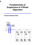
Congratulations on choosing the Eagle 2 ARF! This aircraft has been carefully engineered to provide you with all the terrific flight characteristics of the Goldberg Eagle 2 kit, a plane that has helped
thousands of R/C pilots earn their wings. Your Eagle 2 ARF's sure-footed ground handling, superb
stability, and super-slow landings will help make your early attempts at R/C flying successful. But
first, take the time to read carefully through this booklet. It will speed the assembly process, help
ensure that the plane you take to the field performs properly, and will increase your understanding of
the challenging and fun sport of R/C flying.
WARNING
A radio-controlled model is not a toy and is not intended for persons under 16 years old. Keep
this kit out of the reach of younger children, as it contains parts that could be dangerous. A radiocontrolled model is capable of causing serious bodily injury and property damage. It is the buyer's
responsibility to assemble this aircraft correctly and to properly install the motor, radio, and all other
equipment. Test and fly the finished model only in the presence and with the assistance of another
experienced R/C flyer. The model must always be operated and flown using great care and common
sense, as well as in accordance with the Safety Code of the Academy of Model Aeronautics (5151
Memorial Drive, Muncie, IN 47302, 1-800-435-9262). We suggest you join the AMA and become properly insured prior to flying this model. Also, consult with the AMA or your local hobby dealer to find an
experienced instructor in your area. Per the Federal Communications Commission, you are required
to use only those radio frequencies specified "for Model Aircraft."
LIMITED WARRANTY
Carl Goldberg Products has inspected and certified the components of this aircraft. The company urges the buyer to perform his
own inspection, prior to assembly, and to immediately request a replacement of any parts he believes to be defective for their
intended use. The company warrants replacement of any such components, provided the buyer requests such replacement within a period of one year from the date of purchase and provided the defective part is returned, if so requested by the company.
No other warranty, expressed or implied, is made by the company with respect to this kit. The buyer acknowledges and understands that it is his responsibility to carefully assemble the finished flying model airplane and to fly it safely. The buyer hereby
assumes full responsibility for the risk and all liability for personal or property damage or injury arising out of the buyer's use of the
components of this kit.
CARL GOLDBERG PRODUCTS, LTD.
P.O. Box 88 Oakwood GA 30566 Phone #678-450-0085 Fax # 770-53-63 www.carlgoldbergproducts.com
© Copyright 1999 Carl Goldberg Products LT.
1
ITEMS NEEDED TO COMPLETE
THIS AIRCRAFT
TOOLS AND SUPPLIES
REQUIRED FOR ASSEMBLY.
1
RADIO GUIDANCE SYSTEM (4
CHANNEL MINIMUM REQUIRED)
1
ENGINE .40-.45 2-CYCLE, AND
MUFFLER
(a 4-cycle engine is NOT recommended)
1
CA ACCELERATOR
1
2 OZ. BOTTLE CA GLUE
1
1/2 OZ. BOTTLE CA GLUE
1
20-MINUTE EPOXY
20
#64 RUBBER BANDS
ROLL OF WAXED PAPER
MODELING OR UTILITY KNIFE
WORK SURFACE (24" x70")
ELECTRIC DRILL
1/8", 1/16", 3/32" DRILL BITS
SMALL STANDARD & PHILLIPS
SCREWDRIVERS
MASKING TAPE
NEEDLE NOSE PLIERS
YARD STICK
FLEXIBLE STRAIGHT-EDGE
30-60-90° x 6"
ENGINEERING TRIANGLE
SOFT PENCIL
A FEW STRAIGHT OR "T" PINS
ADJUSTABLE WRENCH
WIRE CUTTER (DYKES)
HAIR DRYER
(OR OPTIONAL HEAT GUN)
ACID BRUSH
OPTIONAL
1
PIECE OF MEDIUM SANDPAPER
PAINTS FOR PILOT FIGURE &
COCKPIT
HEAT GUN OR IRON (for covering
touch-up)
1/2” FOAM RUBBER
SWITCH HARNESS
2
GLOSSARY
of common modeling terms
ARC: Almost Ready to Cover
ARF: Almost Ready to Fly
AILERON: the control surface on the wing that rolls (or
banks) the plane
AIRFOIL: the shape of the wing as seen from the end
ANGLE OF ATTACK: the angle at which the wing meets
the air flow
BEVEL: to sand to an angle shape
BURR: the rough edges on a piece of wood or metal after
it is cut
CAP STRIP: a thin strip glued to the edges of the ribs to
shape the wing
CONTROL HORN: a device attached to each control surface to provide an attachment point for the pushrod
COWL (COWLING): the nose section of the fuselage that
encloses the engine
DECALAGE: the difference between the incidence of the
wing and stabilizer
DIHEDRAL: the upward angle of the wings, as seen from
the front
ELEVATOR: the moveable part of the horizontal tail, which
controls pitch
EMPENNAGE: the tail of the plan
FIN: the fixed vertical part of the tail
FIREWALL: the plywood former at the front of the fuselage, to which the engine is mounted
FORMER: a piece which shapes the fuselage; and to
which the sides of the fuselage are attached.
GUSSET: a small triangular piece glued into a corner to
strengthen it
INCIDENCE: the angle of the wing or the tail in relation to
the thrustline
LAMINATE: to glue two thin pieces of material together to
form a thicker, stronger piece
LEADING EDGE (L.E.): the front edge of the wing that
first meets the airflow
LONGERON: a stringer that runs the length of the fuselage
PITCH: an up and down movement of the nose of the
plane, which is controlled by the elevator
PROTOTYPE: the full scale airplane from which the model
design was taken
PUSHROD: the long, stiff dowel or wire that connects the
servo with the control horn
RECEIVER ("Rx"): Receives radio signal
RETRACTS: (Retractable Landing Gear) devices for
extending and retracting the wheels on command
3
RTF: Ready to Fly
RIB: the airfoil-shaped piece that connects the leading
edge, spars and trailing edge of the wing together and
holds them in shape
ROLL: tilting of the plane as viewed from the front, controlled by the ailerons
RUDDER: the moveable vertical tail of the plane, which
controls yaw
SERVO: the part of the airborne radio system that moves
the control surfaces
SERVO ARM (OUTPUT ARM, SERVO WHEEL): the
piece that attaches to the servo and connects it to the
pushrod
SHEAR WEB: wood sheeting that connects the top and
bottom spars to stiffen the wing
SHIM: a thin piece of wood or other material inserted
between two other pieces to improve their fit
SPAR: a wooden stick running lengthwise through the
wing that serves as its backbone
SPINNER: the rounded cone that fits over the propeller
hub
STABILIZER (STAB): the fixed horizontal part of the tail
STALL: a situation in which the plane is flying too slowly
to move sufficient air across the wing to produce lift
STRINGER: a long piece of wood attached to the formers
to shape the fuselage
THRUSTLINE: a line drawn from the center of the propeller hub straight through the airplane
TORQUE: a rolling tendency caused by the spinning propeller
TRAILING EDGE (T.E.): the edge of the wing that faces
the rear of the plane
TRANSMITTER ("Tx"): Transmits radio signal to servos
TRIM: small adjustments made to the control surfaces to
cause the plane to fly straight and level by itself
WASHIN: a twist in the wing that makes the trailing edge
lower than normal
WASHOUT: a twist in the wing that makes the trailing
edge higher than normal
WING SADDLE: the shaped part of the fuselage in which
the wing rests
WHEEL COLLAR: a metal ring that holds the wheel on
the axle
YAW: a right-to-left movement of the nose, controlled by
the rudder
INTRODUCTION
USING THIS INSTRUCTION MANUAL
Before you begin assembling your Eagle 2
ARF, take some time to read through this entire
instruction book. It is designed to take you stepby-step through the process and to give you
added information on engine and radio selection
and set-up, balancing your aircraft, and flying
your model. The time you spend will speed the
assembly process and help you avoid problems.
CONSTRUCTION TIPS
If you have never assembled a built-up
model before, the following tips will prove helpful.
IMPORTANT: ALWAYS READ A FEW
STEPS AHEAD. This will alert you to coming
instructions and will help you plan accordingly.
Using the Parts Identification section,
familiarize yourself with the various items included in your kit box.
As you work, CHECK OFF EACH STEP
in the box provided, so that you are sure you do
not forget anything.
PREPARING FOR ASSEMBLY
Do not hesitate to ask questions. Your
You will need a work table of approximate- local hobby dealer and area flyers will most likely
ly 24 x 70" which has been covered to protect it
by happy to help, as they want you to have a
from adhesive and paint drips, as well as cuts
successful flying experience. You may also
and other damage. Many people cover their
receive technical assistance from Carl Goldberg
work area with a sheet of dry wall (sheet rock)
Products via e-mail (questions@goldbergprodand/or waxed paper to prevent CA glue and
ucts.com) or by telephone 1-678-450-0085.
Epoxy from ruining the work surface.
SELECTING RADIO CONTROL EQUIPMENT
CHOOSING A RADIO
IMPORTANT: When selecting a radio, remember
that there are many radio frequencies available,
but not all of these frequencies can be used
legally to operate model airplanes. Be sure to
tell your dealer that you want a radio with a
"Model Airplane" frequency.
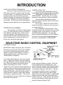
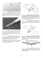
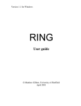
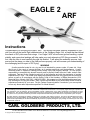
Your model was designed to use a four-channel
radio. In flight, the model is controlled primarily
by using the ailerons and the elevator (see drawing). One radio channel controls the aileron,
which is the primary turn control. It rolls, or
"banks" the model. Another channel operates the
elevator, which controls the pitch (climbing, level
flight, and descent). The third channel is for the
engine throttle and controls the engine speed. A
fourth channel is used for rudder, which assists
the ailerons in turning the aircraft. The new R/C
flyer probably will use the rudder only for steering
the model on the ground.
4
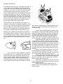
Radios are battery powered with rechargeable
nickel-cadmium batteries (ni-cads). Such sets
come equipped with a recharging unit. Also,
many of the radio systems now available feature
"servo reversing" switches which allow the pilot
to reverse the response of the servo. This feature simplifies installation and is a worthwhile
consideration when selecting a radio system.
Other radios come with a variety of sophisticated
features, such as dual rates, exponential and
control mixing, etc. These features are typically
used by more advanced flyers and are not necessary for flying the Eagle 2 ARF
ENGINE & PROPELLER
Your plane flies well using any 2-cycle engine size from .35
to .45. (We do not recommend a 4-cycle engine for this
aircraft, due to the more complicated set-up required.) The
numbers .35 to .45 refer to the amount of space the piston
moves through inside the cylinder of the engine. This
space is called displacement; larger displacement generally means more power. If you live in a hot climate, or your
flying field is approximately 3,000 feet or more above sea
level, you should stay with a .45 engine. It's a good idea to
select an engine that is popular at the flying field, so that if
you have any engine problems, other modelers will be
familiar with the engine and be able to help.
The propeller size must be matched to the engine. For
example, a .35 may use a 9" diameter prop while a .45 can
use a 10" prop. Refer to the information that is supplied
with your engine for recommended propeller sizes. It's
wise to buy a few spare props, as everyone breaks them
occasionally, and particularly often when learning to fly.
The following equipment will be needed at the flying field
to start your engine, make adjustments, and clean your
model after flying.
FLIGHT BOX: Something sturdy in which to carry
your
equipment.
CGP's quick-building MiniTote carries the
Balancing your propeller helps to protect your radio from
basics:
fuel,
starter
and battery, and a few essential tools.
the damaging effects of vibration. There are good, easy to
The
larger
CGP
SuperTote
or Monster Tote are both ecouse prop balancers on the market. Follow the instructions
nomical,
easy
to
build,
and
pack lots of utility into little
that are supplied with the prop balancer. Never carve or cut
space.
They
hold
fuel,
transmitter,
starter & battery, as
a prop near the hub for any reason (such as to fit a spinwell
as
many
tools,
in
a
balanced
load
that is easy to carry.
ner).
STARTING BATTERY AND GLO-PLUG CLIP: A 11/2 volt battery is required to heat your engine's glo-plug
for starting. Wires connect the glo-plug clip to the battery.
Because engine starting draws a lot of electric power from
the battery, rechargeable ni-cad batteries are recommended. Although they cost more initially, they are more economical in the long run than frequently replacing dry-cell
batteries.
FUEL: For best engine performance, use the fuel
recommended by your engine's manufacturer. 2 and 4cycle engines require different fuel blends. Ask your dealA 2-1/4" CGP 4-Pin Snap-On Spinner is included
er to recommend a good quality 5-10% Nitro fuel.
in the Eagle 2 ARF. It is a rugged precision molded spinFUEL PUMP: Needed to transfer fuel from the fuel
ner that does not require any special mounting nuts or
can to the model's fuel tank. A simple squeeze-type bulb
screws. Carefully read the spinner instructions and warnwill do for small tanks, whereas manual crank or electric
ings included in this book. Although a spinner helps
pumps fill larger tanks more quickly.
reduce the chance of injury from a rotating prop, extreme
FUEL LINE: Have about 3 feet of silicone fuel line
caution always must be used when the engine is running.
to make connections between the fuel pump, the fuel can,
and the model's fuel tank.
EXTRA PROPS: Experts always have a few
spares on hand, so flying doesn't have to stop due to a
broken propeller.
5
6
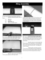
Wing Assembly
NOTE: If the covering on your aircraft has wrinkled in transit, refer to the "Covering" section earlier in this book.
1.
Collect the following wing parts, as shown
above:
(1)
Right wing
(1)
Left wing
(3)
Wing joiners
(1)
Aileron servo plate
(2)
Aileron servo plate supports
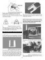
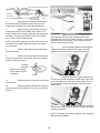
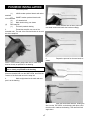
2.
Although the control surfaces of the Eagle
ARF have been glued in at the factory, apply a drop of
Instant (thin) CA glue at each hinge location, for added
security. Allow the glue to wick into the hinge slot.
4.
Holding the three wing joiner pieces
together, with the angle cut facing up, insert them into the
joiner pockets in both the right and the left wing halves.
The joiners should fit easily in the pockets and the wing
halves should meet in the middle, with the wing dihedral
forming a broad "V".
5.
Working on a protected surface, and with
paper towel handy for cleaning fingers, THOROUGHLY
mix 1-2 large (soup) spoons each from bottle A and bottle
B of 30 min. Epoxy. (Use equal amounts of each part, mix
with a stick in a plastic or paper cup or on a sheet of
waxed paper.)
6.
Spread the epoxy on the three joiners and
laminate them to form a single piece. Then put additional
epoxy in each wing pocket and spread a thin layer along
one side of the entire center joint area. Immediately proceed to next step.
7.
Working rapidly, so that the epoxy does
not set before you are finished, slide the laminated wing
joiner into one wing pocket and then slide the other wing
half onto the joiner until the wing halves are touching.
3.
When dry, make sure the hinge installation
is firm by gently pulling on each hinge location.
7
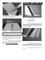
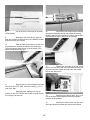
8.
Using masking tape, tape the wing halves
together at the trailing edge and close to the leading edge
together, as shown. This will help keep the wing from twisting.
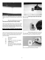
2.
Place the servo tray over the servo opening in the center of the wing, as shown. Trace the outline
of the servo tray.
9.
Next, place additional tape at several locations across the center seam of the wing, so that the
halves stay firmly together while the epoxy is setting.
NOTE: The wing dihedral will force one side of the wing up
off the tabletop. Place a book under the high side to help
support the wing and keep the halves in the proper position. Caution: Do not distort the wing by blocking it too high
and do not touch until the epoxy dries.
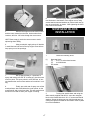
AILERON SERVO INSTALLATION
NOTE: Each radio manufacturer has its own way to mount
the servos. Therefore, read the instruction manual included with your radio to understand exactly how the servo
should be mounted.
1.
(1)
(1)
(2)
(2)
(2)
(1)
(1)
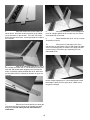
3.
Being extremely careful not to cut into the
wood underneath, cut the covering along the outline and
remove the covering in the area where the tray will fit.
Collect the following parts:
Horn bracket
Servo tray
¼" sq. x 1-3/4" wood servo tray supports
Snap links
7" wires threaded on one end
Snap nut star tree.
Servo and the necessary mounting hard
ware (grommets, brass eyelets) supplied
with the radio.
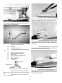
4.
Using CA glue, glue the servo tray supports to the bottom of the servo tray, as shown.
8
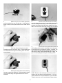
5.
Gather one servo, four rubber grommets,
and four eyelets from your JR radio box. If using another
brand of radio, use the parts called for in the radio instructions.
8.
Place the servo into the servo-mounting
tray and enlarge the opening, if needed. Mark the location
of the mounting screws. Using a 1/16" drill bit, drill the
holes for the screws which have been supplied with your
radio. Then mount the servo into the servo tray, as shown.
6.
Place the rubber grommets over each
mounting lug on the end of the servo. These rubber grommets will prevent the lugs from breaking when the servo
moves around.
9.
With the servo arm positioned nearest the
trailing edge, place the servo assembly in the wing opening and check the fit. Enlarge the opening, if needed. The
wire should exit under the tray, allowing the servo to fit
down into the wing. When satisfied with the fit, apply CA
glue to each tray support and glue assembly in place.
7.
Working from the bottom of the mounting
lug, put an eyelet into each hole. This prevents the mounting screw from being over-tightened when the servo is
mounted.
9
NOTE: The servo arm on the top of your servo must be
similar to the one shown in the photo above. If it is not,
choose another arm from the selection in your radio box.
Twist the servo arm until it is positioned as shown above.
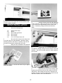
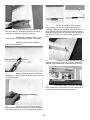
10.
Thread the mini-snap links onto the two 7"
threaded wires until the wire shows in the middle of the
snap link.
16.
For ease of installation, remove the servo
arm, as shown, and take two snap nuts from the snap nut
tree.
17.
Insert the pushrod through the bottom of
the servo arm and then push (snap) the snap nut on top,
to hold the pushrod is held in place. (Pliers may be helpful.)
11.
Thread the horn brackets on the aileron
torque rods. Be sure to screw them down until they are
flush with the top of the torque rods.
12.
Referring to the above photo, install the 7"
pushrod with the snap links connecting to the horn brackets.
18.
Starting at the top of the servo opening,
press the wide white vinyl tape down over the joined wing
seam. MAKE SURE THE MIDDLE OF THE TAPE COVERS THE CENTER JOINT OF THE WING, WITH HALF
OF THE TAPE ON EACH SIDE OF THE SEAM. Apply the
tape all the way around the wing, stopping at the bottom of
the servo hole. Cut off any excess tape. Peel off the clear
tape on the surface of the white tape.
13.
To make pushrod installation easier, tape
the ailerons to the wing in the center (level) position .
14.
Lay the pushrods on the top of the servo
arm and mark where the rod meets the outside hole.
19.
Re-install the servo arm on the top of the
servo and reattach the push rods to the control horns. Be
sure to REMOVE THE TAPE FROM YOUR AILERONS, so
they will be able to move later, when you are setting up
your radio.
15.
Remove the pushrods from the horn bracket. Make
a 90° bend at the mark. Then, cut off the NON
THREADED end at approximately ½" from the
bend.
10
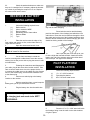
This completes your wing.
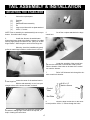
TAIL ASSEMBLY & INSTALLATION
MOUNTING THE STABILIZER
1.
Collect the required parts.
(1)
(1)
(1)
(1)
(1)
(2)
Fuselage
Wing
Stabilizer/Elevator assembly
Fin
Large control horn with nut plate attached
2-56 x ½ "screws
NOTE: Prior to assembly, the stab assembly has no top or
bottom. Use either side to begin.
5.
control horn.
Cut off the nut plate attached to the large
2.
As with the ailerons, the stab/elevator
hinges have been glued at the factory, However, for added
security, apply a drop of Instant 30 min.. (thin) CA at each
hinge location. Allow the glue to wick into the hinge slot.
When dry, check the installation by gently
pulling on each hinge location to confirm that it is secure.
6.
Locate the centerline of the control horn
right over the centerline on the elevator. With a pencil,
mark the location of the holes on the base of the control
horn onto the elevator.
7.
Drill a 3/32" diameter hole through the elevator at each hole location.
3.
Locate the center of the stab and mark it
at the hinge line.
With the stab assembly on end, use your
triangle to draw a line across the stab, as shown.
#2-56 x 1/2”
Machine Screws
Control
Horn
Nut Plate
8.
Place the large control horn on the elevator and push the 2-56 x ½" screws through the holes.
4.
Continue the line across the elevator and
around the Leading Edge of the stab to the top side, to
help in locating the control horn.
11
9.
Holding the screws in place, turn the elevator over and place the back plate (cut from the control
horn) over the screws. Tighten the screws, a little at a time,
until the wood just starts to dent. Set the stab aside for
now.
12.
Mount the wing on the fuse, using #64
rubber bands. Measure carefully, as shown above, from
the fuselage sides out to the wing tips ("A" arrows) to be
sure the wing is centered. Then measure from the wing
tips to the back end of the fuselage ("B" arrows) to make
sure the wing is square with the fuse.
13.
Using masking tape or a washable marking pen, mark the wing center at the leading and trailing
edges. Mark the top of the fuselage at the wing centerpoint.
10.
Mark a centerline down the stab platform
area, as shown. Be sure to extend the line onto the covering on top of the fuse and onto the back of the fuse, so
that you will be able to locate the center once you have put
the stab in place.
14.
Using no glue, and with the control horn
pointing down, trial fit the stab onto the fuse, adjusting it as
needed to line up with the wing. Measure from the stab
tips to the fuse front ("C" arrows) to make sure the stab is
square with the fuse.
11.
Using a twisting motion, insert the wing
dowels through the fuselage cabin. The dowels should
protrude an equal distance on either side of the cabin.
When satisfied with the location, glue in place.
OPTIONAL: Before flying your airplane, seal the exposed
ends of the wing dowels and any other unprotected wood
surfaces with fuel proof paint .
15.
View the model from the rear, as shown,
to see if the stab is level, with respect to the wing. If not,
cut paper strips about ¼ x 1" and shim under the low side
until the stab is level.
12
INSTALLING THE FIN
16.
When satisfied with the fit, draw match-up
lines on both the stab and the fuse to show the correct
location of the stab on the fuselage.
1.
Collect the following parts:
(1)
(1)
(2)
Fin/rudder assembly
Small control horn
#2-56 x ½" screws
2.
Remove the wing. Add a drop of thin CA
to the fin/rudder hinges, as you have done with the aileron
and elevator hinges. When dry, CHECK TO MAKE SURE
THE HINGES ARE SECURELY GLUED by pulling gently,
but firmly, on the rudder.
CAUTION: In the following step, take great care to avoid
cutting into the wood structure underneath the covering!
17.
Using a sharp-bladed hobby knife, strip
covering from the stab at the points where the stab and
fuse mate, being sure to leave 1/8" to 3/16" of covering
overlap, as shown above. Erase any marks that will show
after the installation.
18.
Mix epoxy as before (about 2 large spoonfuls), and glue the stab in place on the fuselage. Check
again to make certain the tail assembly is level and
straight. Allow epoxy to dry THOROUGHLY.
3.
Making sure your rudder/fin assembly is
facing the same direction as the above photo, measure up
from the bottom of the rudder ½" (12 mm.) Put a mark,
next to the hinge line, for the location of the control horn.
4.
trol horn.
13
Separate the nut plate from the small con-
5.
Place the control horn on the rudder, as
shown above, and mark the hole locations on the rudder,
just as was done on the elevator. Then drill 3/32" holes
and mount the control horn, screwing through the rudder to
the nut plate.
8.
Remount the fin back on the fuselage and
put a 90° triangle against the fin to make sure it is mounted perpendicular to the stab.
9.
When satisfied with the fit, mix up a couple
of spoonfuls of epoxy.
10.
Remove the fin and apply a thin, even
coat of epoxy on the bottom of the fin and along both sides
of the fin mounting posts. Be careful not to apply too thick
a coat of epoxy, to avoid the glue squeezing out from
underneath the fin.
6.
Slide the fin mounting posts into the top of
the fuselage and check the fit. The fin should fit easily into
each slot and should stand upright by itself. Enlarge the
holes, if necessary. When satisfied with the fit, draw lines
on both sides of the fin, showing its location on top of the
fuselage.
11.
Mount the fin on the fuselage and place
the 90° triangle against the fin. Use masking tape to hold
the triangle in place until the epoxy dries. Make sure to
not glue the triangle!
7.
Remove the fin and carefully trim away the
covering where the fin mounts on the fuselage and stab,
being sure to avoid cutting into the wood structure
underneath.
14
INSTALLING FUSELAGE COMPONENTS
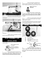
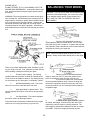
SPINNER ASSEMBLY
Repeat This Sequence
CAUTION: The spinner, propeller, and engine, if improperly
installed, or if misused, may result in serious injury to you
or to others. Follow the spinner assembly instructions, and
other instructions and warnings elsewhere in this book,
carefully.
General Precautions:
·
Never use a spinner where the cut-out is too small
for the propeller you are using.
·
Follow the engine and prop mounting instructions.
·
Inspect frequently, and discard any prop with nicks,
scratches, splits, cracks, or any other signs of damage.
Never repair a prop!
·
Inspect for loosening and retighten using a prop
wrench.
·
Make sure you and any spectators are not in the
plane of rotation of a prop.
·
Protect you eyes with safety glasses.
·
Get expert advice from your dealer or equipment
manufacturer, if you have any questions or concerns
regarding the spinner, engine, or propeller.
Push Stright Into
Slots
Bushing
Bushings Furnished
With 2” to 3” Spinners
only
Select
Best
Bushing
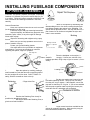
4.
Place the backplate on the engine. It
should fit
snuggly. If it does not, add one of the
bushings provided, using a drop of glue to secure it, if necessary.
Locating Pins
1.
Open the spinner by carefully pushing a
small screwdriver (one that does not exceed the width of
the slot) straight into all four slots. DON'T TWIST! For
safety, hold the screwdriver close to the tip.
Retaining
Pin
3.
"Work in" the spinner by assembling and
disassembling three or four times, rotating the pins each
time before snapping the spinner to the backplate. The
spinner will be quite stiff, at first. You may also boil it in a
pan of water for 20 minutes to rehydrate the nylon and
make it more workable.
5.
Set the prop against the locator pins and
hold while tightening the nut. The prop may turn away
from the pins, as you tighten. If this happens, secure the
prop with a small drop of CA glue. If you are not satisfied
with the prop-to-spinner match-up using the locator pins,
rotate the prop 90° and adjust prop as desired.
Finger Lube Pins
Clearance All Around
Thread
2.
Examine the Retaining Pins closely for
possible tiny threads and remove.
Rub fingers around the Retaining Pins, to
give them a little lubrication.
6.
Large cutouts have been molded into the
spinner for propeller clearance. Make sure the prop you
have selected has clearance all around.
15
7.
Close the spinner by positioning the
spinner with the retaining pin at the top and
squeezing the backplate onto the nose cone.
Rotate the next pin to the top and repeat, until all
four pins are secure.
2.
With the "R" facing up and on the right
side of the aircraft, as shown, place the motor mount in the
fuselage. but do not glue at this time. Position your engine
on top of the motor mount.
NOTE: The motor mount cutout will accept most standard size motors. However, if your motor is wider than
the mount, carefully trim equal amounts from both
sides of the opening, until your engine fits. Preserve
the right offset, as described above.
8.
Examine the spinner for good fit.
Make sure there is no distortion evident. Look
for a slight separation between the spinner cone
and the backplate, as shown above.
MOTOR MOUNT INSTALLATION
NOTE: Make sure the tail assembly is thoroughly
dry before removing the triangle and continuing.
3.
Slide the engine to the rear of the opening
until the back of the spinner has clearance of approximately 1/8".
1.
Place the wooden motor mount on
your work surface, exactly as shown above. The
cut out for the motor should offset, so that there
is a little more wood in the lower the right corner.
This will give your engine right thrust. Write the
letter "R" in the upper right hand corner to mark
the top and the right side of the motor mount.
16
4.
When you are satisfied with the fit, use a
pencil to mark straight down through the engine mounting
holes onto the motor mount.
9.
After the epoxy dries, permanently install
four blind nuts in the bottom of the engine mount, using
socket head screws and washers to pull the blind nuts up
into the screw holes, as shown. After tightening the blind
nuts, remove the screws.
NOSEGEAR BLOCK
INSTALLATION
5.
Remove the engine from the motor mount
and the motor mount from the fuse. At the marked hole
locations, drill four 1/8" holes through the motor mount.
HINT: Place scrap ply under the motor mount to avoid
splintering when drilling.
6.
Using a toothpick, apply a drop of Vaseline
in each blind nut hole and on the top engine screw hole to
keep epoxy out of the openings.
1.
(1)
(1)
Collect the following items:
Nosegear block
(4)
4-40 x ½ socket head screws
(4)
4-40 blind nuts
# 4 washer
7.
Mix up approximately 2-3 spoonfuls of
epoxy and making sure the "R" is facing up, glue the motor
mount in place. The epoxy should cover all areas of contact between the motor mount and the rail on which it is sitting.
8.
Finally, put a thin coat of epoxy over all the
wood surfaces: above and below the motor mount, on the
wood firewall, and on the fuse sides. This will protect these
areas from fuel and oil when your engine is running.
17
2.
Turning fuse upside down and using the
Allen wrench supplied with this kit, screw the nosegear
block to the firewall with the 4-40 x ½" screws and the #4
washers. Screw the bolts part way until the ends are just
coming through the backside of the firewall. Refer to photo
for correct installation.
3.
Turn the fuse right side up and place the
4-40 blind nuts on the ends of the screws, with the teeth
pointed toward the firewall.
4.
Place the servos in the tray and install with
screws, as shown. Make sure the servo arms and wheels
on your servos look approximately like the ones in the
photo. If necessary, change the arms and wheels to
match.
SERVO INSTALLATION
1.
Collect the following items:
(2)
(3)
(12)
(12)
(12)
(1)
Plywood servo trays
Servos
Servo rubber grommets
Servo eyelets
Servo screws
¼ x½ x 3-5/8 wood servo rail
2.
Set up the three servos in the same manner as the wing servo was prepared. Review the Wing
Assembly section of the book, if necessary. Also refer to
the specific instructions included with your radio.
3.
Using Ca Glue, laminate the two plywood
5.
Position the ¼ x ½ x 3-5/8" wood servo
rail inside the fuselage, fitting it into the notches in the side
doublers. If the rail is too tight, sand to fit. When satisfied,
glue in place.
servo trays together. Hold flat and allow to dry.for approximately one minute.
6.
Slide the servo tray into the fuselage, placing the back of the servo tray into the notches in the rear
cabin former. After making sure the tray is straight in the
fuselage, CA glue in place by putting glue on top of the rail
and at the notches in the rear cabin former.
18
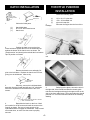
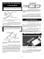
HATCH INSTALLATION
THROTTLE PUSHROD
INSTALLATION
1.
Hatch
Hold - Down
“Straight Action”
End
1.
#2 x 3/16 Sheet
Metal Screw
(1)
(1)
(1)
Collect the follow parts:
(1)
(3)
(1)
Collect the following parts:
2.
fuselage.
Hatch hold-down
#2 x 3/16" sheet metal screw
Hatch cover
2.
Position the hatch cover on the fuse.
Press hold-down against the front of the firewall and up
against the bottom of the hatch cover, as shown. The
"straight action" end should point towards the fuse bottom.
Tape in position on firewall.
3.
rod.
1/8" x 10-1/2" nylon tube
.072 x 19" threaded rod
nylon mini-snap link
Remount the engine into the front of the
Screw the mini-snap link onto the threaded
Remove the hatch cover and apply CA
glue to the hold down. Replace the hatch cover on fuse,
gluing it to the hold-down. Allow to dry.
#2 x 3/16 Sheet
Metal Screw
3.
When dry, remove the hold-down/hatch
assembly from the firewall and drill two 1/16" pilot holes.
Secure the hold-down to the hatch with the two 3/16"
screws.
4.
Referring to the photo, start at the hole in
the right side of the firewall and slide the throttle guide
tube into the fuselage and through the upper notch on the
side of the front cabin former. The nylon guide tube should
protrude 1/8" out of the firewall as shown in the following
drawing.
#2 Shoulder Screw as Mounted in Firewall
Note: Unthreaded Shank
4.
Reposition the hatch on the fuse. Mark
the location for the #2 screw and install the screw on the
firewall, as shown. Be sure to leave enough of the
unthreaded shank to engage the hold-down. Snap on and
off several times, to make sure the screw is properly
secured.
19
Nylon Tube protrudes 1/8” Out Firewall
Simulating
Servo Action
Nylon Guide Tube
Throttle Rear Limit
(usually Idle Position)
Front Limit
(usually Full
Power
5.
Referring to the drawing, and starting at
the firewall, slide the threaded rod into the nylon tube.
Connect the mini-snap link to the engine throttle arm.
6.
Again referring to the drawing, move the
pushrod back and forth to simulate servo action. If the
pushrod does not move freely, adjust the wire bend where
necessary. Test the front and rear "limits" of the throttle
arm, to have a feel for what they are.
NOTE: Later, when setting the controls, make sure to set
the throttle servo linkage within the range of the throttle
arm movement.
11.
Replace the servo arm on the throttle
servo and twist the servo arm clockwise until it stops.
Reposition the servo arm, as well, so that it is in the same
position as shown in the photo. Then replace the screw
into the center of the servo arm.
12.
Pull the throttle pushrod back through the
untightened pushrod connector until it stops, and then
tighten the setscrew on top of the pushrod connector.
7.
Glue the nylon tube to the firewall and to
the second former.
8.
Remove the servo wheel from the throttle
by removing the screw on the center of the arm and then
pulling up gently on the arm.
Pushrod
Connector
Broken View Through
Servo Wheel To Show
Installation
9.
Install the push rod connector on the servo
arm as shown.
10.
Guide the throttle pushrod wire though the
pushrod connector and slide the servo arm up to the throttle servo.
13.
When the setscrew is tight, twist the throttle servo arm counter-clockwise until the servo stops. Now
look at the carburetor in the front of your engine. The carburetor should be open (high speed) all the way, just as
shown above.
14.
Now twist the throttle servo arm clockwise
until the servo stops. At this point, the carburetor should be
closed (slow speed).
NOTE: The throttle servo will be adjusted more accurately
after the radio installation.
20
3.
Make a ¼" bend at one end of the 16-3/4"
wire. Then, referring to the photo, bend the wire at approximately a 20° angle about 1" back from the first bend.
15.
Cut the excess throttle pushrod wire sticking out beyond the pushrod connector. Leave about a ½"
of wire, to allow for adjustments.
Gather the necessary items:
4.
With the fuselage bottom-side up, insert
the unbent end of the wire into the hole on the opposite
side from the throttle pushrod and nearest the bottom of
the fuselage.
(1)
(2)
(2)
Fuselage
Main gear wire struts
¾" landing gear straps (measure hole to
5.
With the fuselage right side up, make sure
the pushrod is going through the side slot closest to the
fuselage bottom in the front cabin former.
(4)
(1)
(1)
(1)
(1)
(1)
(1)
#2 x 5/16 sheet metal screws
Nylon nosegear steering arm
Wheel collar
6-32 x 3/16 socket head screw
5/32 nosegear strut
Nylon snap nut
16-3/4" wire
1.
hole)
Steel Collar
Steering Arm
#6-32 x 3/16 Socket Head Screw
6.
With the fuse UPSIDE DOWN, Place the
wire on the outermost hole on the nylon steering arm.
Fasten the nylon snap nut on the end of the wire to hold
the steering arm in place.
2.
Making sure the side holes are aligned,
press the steel collar into the pocket in the nylon steering
arm.
Thread the #6-32 x 3/16" socket head
screw in a few turns.
21
7.
Install the steering arm in the bearing.
Slide the nosegear strut though both the steering arm and
the nosegear bearing. With the fuse bottom-side up, tighten the socket head screw with the Allen wrench.
8.
Put the nosegear strut into the nosegear
block, pushing it down until the spring is approximately ½"
off the bottom of the fuselage. Make sure the nosegear
steering arm is approximately ½" away from the firewall
and that the nosegear strut is positioned as shown in the
photo.
12.
Bend the wire towards the correct hole in
the rudder servo wheel., but DO NOT CUT IT. Move the
pushrod to check for free movement and correct, if necessary.
13.
With the nose wheel pointing straight
ahead, the end of the steering arm should be ½" away
from the firewall. Adjust, if necessary. At the servo, mark
where the pushrod meets the hole on the servo wheel and
make a 90° bend in the pushrod at that point.
14.
Remove the servo wheel to insert the
pushrod, and then remount. Later, during taxi tests, you
can adjust the nose wheel steering by loosening the steering arm socket head screw.
Fuel Tank
Installing Main Gear
Struts In Fuse Bottom
#2 x 5/16
Sheet Metal
Screw
9.
Using the 6-32 Allen wrench, tighten down
the setscrew in the steering arm to hold the strut in place.
22
1. (1)
(2)
(1)
(1)
(1)
(1)
(1)
(1)
Collect the following items:
Fuel tank
Brass tube
Large nylon cap
Small nylon washer
Rubber stopper
#4 x 1” screw
Fuel tank klunk
6” length of white fuel tubing
CAUTION! The white neprene stopper and the fuel
tubing provided with this kit are FOR GLOW FUEL
ONLY; DO NOT USE THESE PARTS FOR GASOLINE.
2. Insert both brass tubes through the wide end of the
rubber stopper. Leave 1/2” extending out the front 6. of the tank.
Place the small nylon washer on both tubes, as
shown, making sure that one of the tubes extends 7. 1” past the washer. This tube will be for the klunk
pickup.
Cut tube as necessary.
Again place the stopper assembly into the fuel tank.
If the klunk is touching the back wall of the tank, trim
it as needed.
Place the large nylon cap onto the two brass tubes.
When satisfied with the fit of the entire stopper
assembly, tighten the #4 x 1” screw into the center
of the stopper. Take care to not over-tighten the
screw.
FUEL TANK INSTALLATION
3. Bend the other tube, at the angle shown, until it
nearly reaches to the fuel tank wall. This is the
vent/overflow tube.
4. Insert the stopper assembly into the fuel tank until
the vent tube is up inside the “bubble” in the fuel
tank wall. Remove the assembly and trim the vent
tube, if necessary.
5. Install the klunk on the white fuel tubing.
Mount the other end of the fuel tubing onto the brass
outlet tube in the stopper.
23
1.
Collect the following items::
(1)
(1)
(1)
½ x 8 x 12" foam rubber (Not Included)
Assembled fuel tank
10" length of fuel tubing
2.
From the ½ X 8 X 12", cut a strip 2-1/2" x
12" long. Next, cut a 2" wide strip across the bottom of the
leftover piece.
5.
Place the fuel tank down inside the hole
on top of the "Z" folded foam. Fold the 2" foam piece in
half and push it down on top of the fuel tank.
3.
Remove the hatch and put the 2-1/2" wide
foam in the bottom of the fuel tank compartment in the
fuselage.
6.
Insert both fuel line ends through the holes
on each side of the firewall, forming a loop around the
engine. Place the ends of the fuel tubing on the brass
tubes on the front of the fuel tank, as shown above.
4.
shape.
7.
With a scissors, cut the fuel line 1" beyond
the carburetor. The shorter line connects to the carburetor
pick up; the longer line goes to the muffler back-pressure
pickup. Replace the hatch.
Fold the foam in so that it forms a "Z"
Replace the hatch on the fuselage.
24
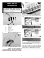
RADIO SWITCH
INSTALLATION
The switch holder shown is not included in the
kit. You can purchase the switch holder at your
local hobby shop. For installation without the
switch holder, cut a hole through the side of the
fuselage to mount the switch.
4.
Locate the hole on the left side (as you
look out the windshield) of the fuselage and make an "X"
cut in the covering. Push the switch mount bolt through the
hole.
1.
(1)
(1)
(1)
(1)
(1)
(2)
Gather the necessary parts:
Radio switch
Switch mount
Switch cap
Switch mount bolt
Switch push-pull
#2 washer
5.
Place the switch unit on the screw on the
inside of the fuselage, as shown.
2.
Remove the screws and the switch cover
(if your radio has one) from the top of the switch.
6.
Insert the push-pull mechanism through
the center hole in the switch mounting bolt and place the
switch cap over the switch. Screw the push-pull into the
cap. Test for good movement.
3.
Using the screw that you just removed and
the #2 washer, put the switch mount together, as shown.
The switch mount has one slotted hole and
two holes on the other side. Mount your switch so that the
switch itself will move back and forth and you can feel and
hear the click.
25
NOTE: There is a small hole on the side of the switch cap
for the push-pull to screw into. Also, the switch has two different size holes in the top and bottom to enable it to fit
over large or small switches. Choose the opening that best
fits your switch and allows it to move easily in and out.
26
PUSHROD INSTALLATION
1.
Collect the pieces:
(1)
LONG wooden pushrod dowels with wires
attached
(1)
SHORT wooden pushrod dowels with
wires attached
(2)
10" threaded rod
(2)
Black shrink tubing, not shown
(2)
Mini snap link
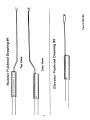
(1)
Full-scale pushrod drawing
5.
When satisfied with the bend, mark the
next bend location and make the bend accordingly.
2.
Thread the snap link onto one of the
threaded rods. The end of the rod should show in the middle of the snap link.
6.
shown.
Repeat the process for the next bend, as
NOTE: In the following steps, take care to match each
bend as closely as possible to the drawing.
NOTE: in the following steps, take care to match each
bend as closely as possible to the drawing.
3.
Using the Rudder Pushrod Drawing #1,
place the threaded rod over the SIDE VIEW and mark the
location of the first bend next to the snap link.
4.
Make a slight bend at the mark and compare it to the drawing.
7.
Mark the fourth bend and then, holding the
wire over the TOP VIEW on the drawing with pliers, twist
the wire until it matches the drawing. Then bend the final
angle down.
27
8.
Cut off the wire to the length in the SIDE
VIEW drawing.
9.
Referring to the above photo, insert the
bent wire end into the hole and slot in the SHORT wooden
pushrod and CA glue in place.
12.
Remove the mini snap link and, inserting
the pushrod assembly through the windshield opening,
thread it down into the tail section. Twist the rod so that it
exits through the hole in the top of the fuselage.
10.
Slide the black shrink tubing over the wire
and wooden rod assembly and shrink with a hair dryer.
Once the tubing is tightly shrunk, glue the edges of the
shrink tubing with thin CA glue.
13.
Replace the mini-snap on the rod, screwing it in until the end of the rod is just showing in the middle of the snap-link. Attach the snap link to the outside
hole on the control horn.
11.
Examine the top of the fuselage and locate
the hole on the LEFT SIDE, under the covering, 1-1/2" in
front of the stab.
Study the photo. Making sure you are
working on the LEFT SIDE of the aircraft, carefully remove
the covering over the hole.
14.
Referring to the above photo, drill a 1/16"
hole in the servo wheel opposite where the nosegear
pushrod will be installed.
15.
Remove the center screw from the servo
wheel and twist the pushrod end onto the servo wheel
28
19.
As with the rudder pushrod assembly,
insert the bent wire end into the hole and slot in the
remaining (LONG) wooden pushrod. CA glue the wire in
place and slide the black shrink tubing over the pushrod
assembly. Shrink with a hair dryer and, when the tubing is
tight, glue the edges of the shrink tubing using thin CA
glue.
16.
Looking down at the top of the fin, make
sure the rudder is in a straight line with the fin. Adjust if
necessary by twisting the snap link in and out.
Examine the nosegear to make sure the
wheel position is straight forward. Adjust, if necessary.
Install the snap nut on the nosegear
pushrod at the servo end.
20.
Thread the pushrod assembly through the
fuselage and exiting out the end, as shown. Attach the
snap link to the outside hole on the elevator control horn.
17.
Mount the snap-link onto the remaining
threaded rod. The end of the rod should show in the middle of the snap-link.
21.
As before, drill a 1/16" hole in the elevator
wheel. Remove the center screw from the elevator servo
arm and twist the pushrod onto the servo arm.
18.
Lay the wire over the Elevator Pushrod
Drawing #2 and mark the location of the bend. Bend the
wire at the mark and cut off to the length on the drawing.
29
22.
Check the stab and elevator to make sure
they are in a straight line. If necessary, adjust the elevator
up or down by screwing the snap link in or out. Replace
the center screw into the servo.
RECEIVER & BATTERY
INSTALLATION
1.
(1)
(1)
(1)
(1)
(2)
(1)
Collect the following required items :
Radio receiver
Aileron extension WIRE
Receiver battery
Remaining piece of foam rubber
Rubbers bands
T-pin
9.
Tuck the battery and the receiver all the
way into the foam wrapping.
Place both the receiver and the battery
pack into the bottom of the fuselage just behind the front
cabin former. Route the receiver antenna through the fuselage cabin and out the top of the fuselage behind the wing.
Both the aileron extension wire and the charging jack wire
should be sticking outside of the fuselage.
2.
Place the receiver near the edge of the
foam rubber and mark a cut line, so the foam area is ½"
larger than the receiver.
3.
Open the antenna and stretch it out.
NOTE: Never change the antenna length. The
length is tuned to the receiver.
4.
Cut the foam and wrap it around the
receiver, securing with a rubber band. Leave the receiver
sticking out, so that you are able to plug the servos in without interference.
5.
Following the instructions and diagrams for
your radio, plug all the servo wires into the receiver. Take
care to connect each servo wire to the proper device, i.e.
to connect the rudder servo to the rudder plug, the elevator
servo to the elevator plug, and the aileron extension wire
to the aileron plug.
6.
Connect one switch plug to the battery
location on the receiver.
10.
Take a pin and push it into the top of your
fin with a slight lean towards the back. Attach the rubber
band to the end of the antenna and put the rubber band
around the pin. Pull tight on the antenna.
PILOT PLATFORM
INSTALLATION
1.
Collect the following required Items:
(1)
(1)
(1)
¼" x ½" x 3-5/8" wood rail
Plywood pilot platform
#2 x 5/16 sheet metal screw
7.
With the remaining foam, cut and wrap the
battery pack, just as you did with the receiver.
8.
Plug the battery wire into the switch wire.
NOTE: The remaining wire on the switch is
the charging jack and needs to be KEPT
ACCESSIBLE.
2.
Place the ¼" x ½" x 3-5/8" wood rail inside
the fuselage, fitting it into the notch on the side doublers.
CA glue in place.
30
2.
Tack glue the figure by applying a few
drops of CA glue at key joint areas. When dry, remove
tape and apply a small amount of glue all along the seam.
PAINT PILOT AS
DESIRED
3.
Insert the front of the pilot platform into the
notches in the front cabin former with the back resting on
the wood rail.
3.
Using artist's acrylics or modeling enamels, which are available in many colors without needing to
mixing required, paint the pilot to suit your fancy. WARNING: Do not use lacquer-based paints, which will destroy
the plastic.
4.
When dry, CA glue the pilot in place on the
platform. You also may paint the interior of the cockpit, if
added realism is desired.
HINT: When painting the pilot's face, leave the eyes white.
Later, when the face has dried, carefully add eye details
with a fine bush or toothpick.
WHEEL INSTALLATION
4.
and the rail.
Drill a 1/16" hold through the pilot platform
Screw the back of the platform to the support rail, using the #2 x 5/16" screw.
1.
(3)
(3)
(3)
(3)
(1)
PILOT ASSEMBLY AND
INSTALLATION
The pilot figure included with your airplane adds an extra
touch of realism.
Collect the following items:
2-1/2" wheels
5/32 wheel collars
6-32 x 1/8" Allen head set screw
5/32 eyelet
.050 Allen wrench (Not Included)
Set Screw
Eyelet
APPLY DABS OF GLUE
AT JOINTS
Axle
Wheel
WHEN DRY, REMOVE
TAPE AND COMPLETE
GLUING
1.
Cut pilot halves apart at the bottom and
trim off scrap. Gently sand the edges of each half, so that
they will be smooth for joining. Carefully align the front
and back pieces and hold together with tape, as shown.
31
Wheel Collar
2.
Install the wheels on the axles, as
shown: eyelet first, then wheel, wheel collar, and
set screw. Glue the eyelet in place with a drop of
CA glue.
INSTALLING THE WINDSHIELD
& SIDE WINDOW
CAUTION: Follow these instructions carefully to
avoid cutting errors or other damage to the plastic.
Outer cut line
6.
Carefully remove the side windows from
the plastic sheet, again making sure to follow the cut lines
provided. Cut front and back windows apart for ease of
installation.
7.
Test fit the windows. When satisfied with
the fit, tack glue in place and then glue around the entire
edge, as described above. Again, use only a thin bead of
glue and take care to avoid smearing any glue on the plastic.
Cut along outside line
APPLYING DECAL
1.
Carefully trim the windshield, as shown,
along the OUTER cut lines provided.
2.
Temporarily set the windshield in place on
the fuselage. Make sure the wing dowels do not interfere
with the correct placement of the windshield, and note
where it contacts the fuse.
OPTIONAL: For added gluing strength, make a series of
pinhole punctures through the covering, at the contact
points. This will allow the glue to penetrate to the wood
underneath.
1.
Using glass cleaner and a soft cloth, clean
model surface thoroughly before applying the decal.
2.
Cut the decal sheets apart in sections, as
needed. Fold the decal in half, front to rear. Open at the
fold and lay the decal out straight. The protective backing
will bubble away from the decal at the fold.
3.
Using a scissors, cut the backing along the
bubble, removing a strip of backing about 1" wide.
Carefully position the decal on the model and stick it in
place. Then, working from the center, rub the decal down
while peeling off the remainder of the backing.
MUFFLER INSTALLATION
3.
Making sure the windshield is properly
centered, tack glue in place at each of the tack points
shown above.
4.
After the windshield has been tacked in
place, go slowly around the entire windshield, applying a
VERY THIN line of glue at the edge of the plastic. (It will
"wick" under and secure the windshield.) Glue a small
area at a time, using minimal amount of glue, keeping
hands clean, and taking care that no glue is smeared on
the plastic. When the CA glue has dried, if a trace of
white film appears inside the windshield, wipe off with a
damp cloth.
1.
Following your engine manufacturer's
instructions, mount the muffler on the engine.
2.
If your muffler has a fuel-line type fitting on
it, use it to "pressure feed" fuel to the engine for smoother
and more reliable running. In this case, the vent line is
connected to the muffler fitting
32
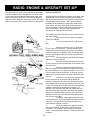
RADIO, ENGINE & AIRCRAFT SET-UP
The transmitter is the part of the radio that the pilot holds.
It usually consists of two sticks that can be moved in 360°
circles, along with slide tabs that help center each movement of the stick for each servo. The following diagrams
illustrate how the radio stick movements control the servos
and the movements of the control surfaces on the aircraft.
SERVO MOVEMENTS
As mentioned in the introductory section of this book, radio
systems with "servo reversing" simplify radio installation.
With a non-reversing system, each pushrod must match its
corresponding servo's rotation. With "servo reversing,"
pushrods can be hooked up to either side of the servo's
output wheel, and after checking the control response, a
servo responding in the wrong direction is easily switched
to the correct action. See your radio manufacturer's
instructions for more detailed information.
The following procedure will help you set up and fine tune
your radio system.
First, remove all servo arms and wheels.
THROTTLE SERVO
1.
Turn on the transmitter (Tx) and receiver
(Rx).
2.
Move the left stick of your Tx all the way
up to the top of its movement. This stick should have a
ratchet feel to it and will stay in any position, up or down,
in which it is placed. In addition, move the trim tab, located to the right of the throttle stick, all the way to the top of
its movement.
3.
Move the throttle pushrod until the engine
carburetor is open all the way.
4.
Remount the servo arm back on the throttle servo, but do not put the screw back in the center of the
arm at this time.
5.
Move the transmitter throttle stick all the
way to the bottom of its movement and observe the opening in the carburetor. The opening should be 1/16" to 1/8".
If, on the other hand, the carburetor is full open, find the
radio's servo reversing switch (see radio instructions) and
switch it.
If the servo is moving in the right direction,
but the movement is not enough, change where the
pushrod is mounted on the servo arm so that the amount
of movement that the pushrod gets from the servo is more
or less. The farther out from the center of the arm that the
pushrod is mounted, the greater the movement. For
example, if the carburetor opening was greater than 1/8"
when the throttle stick was all the way down, the pushrod
needs to be mounted further out on the servo arm; if the
opening was less than 1/16", the pushrod needs to be further in on the servo arm.
In addition, most engines have two holes
on the throttle arm, where the pushrod is hooked up to the
carburetor. The farthest out hole gives the least movement when the pushrod is moved.
6.
When the carburetor is opening correctly,
move the trim tab all the way down to the bottom of its
movement. The carburetor open should be completely
closed. This safety feature allows the running motor to be
turned off
33
7.
When you are satisfied with the responses,
replace the center screw back into the throttle servo.
RUDDER SERVO
2.
Remount the servo wheel onto the servo,
making sure the wheel placement allows the pushrod to be
centered on the servo, just as it was earlier, when the
pushrod was mounted.
The same Tx stick that regulates the throttle, when the
stick is moved up and down, also moves the rudder and
the nosegear steering, when the stick is moved to the right
or to the left. The stick will spring back to the center position when it is released. Also, note that under the
rudder/throttle stick is another trim tab. This trim tab
moves from right to left and will help center the rudder and
keep it in place.
3.
Pulling down on the stick should cause the
elevator to point up. If it goes down, use your reversing
switch to correct the problem.
1.
Move the rudder trim tab into the center of
its movement range.
5.
The full range of elevator movement is
approximately 3/8" up and 3/8" down. If more movement
is needed, move the snap link on the control horn toward
the inside holes.
2.
Remount the servo wheel onto the servo,
making sure the wheel placement allows the pushrods to
be centered on the servo, just as they were earlier, when
the pushrods were mounted.
4.
View the edge of the stab and the elevator
to see that they are in a straight line with each other. Twist
the snap link on the elevator control horn in or out, to
adjust the elevator level with the stab.
6.
When all necessary adjustments have
been made, replace the center screw into the servo wheel.
3.
Hold the rudder stick to the left and see if
the rudder trailing edge, when viewed from behind the
plane, has moved to the left. If it has moved to the right,
then push the servo-reversing switch to correct the movement.
AILERON SERVO
4.
Once the rudder is correctly responding to
the stick movements, look down from the top of the rudder/fin and make sure they are in a straight line with each
other. If not, adjust the snap link in or out on the pushrod
that is hooked to the rudder control horn.
The rudder should move approximately ½"
to each side of center when the transmitter stick is moved.
If your rudder needs more movement, move the snap link
on the control horn toward the inside holes.
When all adjustments have been made,
replace the center screw into the servo wheel.
The same stick that moves the elevator also controls the
ailerons. Moving this stick to the right or left will turn the
aircraft to the right or left. The aileron trim tab, located
beneath the aileron stick, helps the model maintain
straight, level flight.
1.
position.
Move the aileron trim tab to the center
2.
arm.
Remove the center screw and the servo
3.
With the wing resting up against the fuselage, plug the aileron servo into the extension wire coming
out of the receiver.
4.
Remount the servo arm onto the aileron
servo, making sure the arm placement allows the pushrods
to be centered on the servo, just as they were earlier,
when they were mounted.
5.
The nosegear must also be centered. If
adjustments are necessary, loosen the setscrew in the
steering arm and twist the nosegear until it is straight.
When satisfied, retighten the setscrew.
5.
Set the wing on the fuselage, by do not
secure it with rubber bands.
ELEVATOR SERVO
The right stick on the transmitter controls the elevator
servo. Pulling down on this stick will make the plane climb
and pushing up on the stick will put the model into a dive.
1.
Move the trim tab to the right of the stick,
so that it is centered
34
6.
Holding the aileron stick to the left, check
to see that the left aileron trailing edge is pointing up and
the right aileron trailing edge is pointing down. If your
ailerons are reversed, use your servo-reversing switch to
make the correction.
7.
The correct range of motion for the
ailerons is approximately ¼" up or down. If more movement is needed, screw the adjustable horn brackets (into
which the snap links are hooked) down on the wires,
toward the wing.
8.
When all adjustments have been made,
replace the center screw into the servo arm.
ENGINE SET-UP
DO NOT ATTEMPT TO FLY YOUR MODEL UNTIL THE
ENGINE RUNS DEPENDABLY. It should idle without stopping, and the transition through all engine speeds should
be smooth.
WARNING: The turning propeller can cause serious injury,
such as deep cuts. Avoid wearing loose clothing (such as
baggie shirts or neckties) or jewelry which could be caught
by or could fall into the spinning propeller. Children and
spectators should be kept away from a running engine. No
one should stand in line with the propeller. A broken propeller blade becomes a bullet and can seriously hurt someone.
BALANCING YOUR MODEL
IMPORTANT: NEVER NEGLECT THIS STEP WITH ANY
AIRPLANE. If you try to fly a plane with the balance point
behind the recommended range, you run the risk of having an unstable aircraft and the strong likelihood of a
crash. TAKE THE TIME TO PROPERLY BALANCE
YOUR MODEL!
1.
Place the fully assembled aircraft on a
model balancing stand, as shown above. You can make
this simple set-up with a couple of ¼" dowels with rounded
tops, spaced 5" apart. Alternatively, lift the model under the
wing near the fuse by your finger tips.
NOTE: Attach the wing to the fuselage with #64 rubber
bands. Use seven rubber bands on each side of the
fuselage. Always check rubber bands prior to each flight.
There are four basic adjustments which contribute to making your engine run well. First, familiarize yourself with the
above drawing, locating the following four parts.
1.
Throttle "barrel" opening. The rotating
cylinder inside the carburetor is called the "throttle barrel."
It has a hole in the middle to admit air. By rotating the barrel, the throttle can be "wide open" or completely "closed."
2.
Idle/Slow Speed/Stop screw. This screw
allows you to set how much the barrel can close.
2.
Referring to the recommended balance
range (4" back from the L.E.) move the position of the
plane on the balance stand until the model is level.
If you need to support the model outside
the recommended balance range, remove the wing and
shift the R/C equipment away from the heavy end of the
model and recheck until the model will balance within the
acceptable range.
3.
High Speed Mixer or Needle Valve. This
control regulates the mixture of fuel and air at high engine
speeds.
4.
Low Speed Mixer. This control regulates
the fuel/air mixture at idle engine speed.
3.
If shifting the R/C gear still doesn't balance
the model, add weight to the far end of the nose or tail,
respectively, until the model is correctly balanced. The
least weight is needed when added as far back or forward
as possible. Fasten the weight permanently in place.
Follow the break-in instructions included with your engine
make sure it is running well before you go out to fly
35
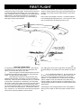
FLYING YOUR AIRPLANE
WHAT TO TAKE TO THE FIELD
Flight batteries, fresh or fully charged
Radio transmitter
Fresh 1 ½ volt starting battery & glo- plug clip
Fuel bulb or pump
Tools for tightening any parts that can vibrate and
loosen
Paper toweling for clean up
Extra #64 rubber bands
Extra props and an extra spinner
Prop wrench
36
WHERE TO FLY
Fly only in areas sanctioned for R/C and known to be free of
radio interference. Ask your hobby dealer or other modelers if
there is an R/C flying field that is used by a local R/C club. This
is the ideal place to fly. If you don't know of an R/C club nearby,
contact the Academy of Model Aeronautics (AMA), at the address
on the front of this booklet, for information on a club in your area.
Remember: R/C flying fields need to have rules to help prevent
accidents, so ask about them before you turn on any of your
equipment! DO NOT TEST your transmitter in the parking lot or
anywhere nearby until you are sure no one else is using your
radio frequency. This could cause another flyer to crash and
make you very unpopular!
If there is no club or other R/C flying site available, locate a
square area (preferably a grassy field), at least four or five football fields long, which is free of power lines, trees, poles, houses,
busy streets and other obstructions. It must be at least three
miles away from any areas where other R/C models, such as
boats or cars, are operated. It should also have a relatively
smooth surface, as it will take practice to learn precision landings. If you find a suitable location, turn your receiver on for 2 or
3 minutes to check that no one in the vicinity is operating an R/C
device which could affect your receiver and cause your plane to
crash.
LEARNING TO FLY
Your chances of success are enormously increased if you have
an instructor. Learning to fly is harder than it looks, and a mistake can seriously damage or destroy your model. Even fullscale pilots have problems learning to fly models because it's different-they're not in the cockpit. It's worth real effort to find
someone to teach you. Many clubs have authorized instructors
and there are even some R/C flight schools. Ask your dealer, or
even check on the Internet to see if there is someone who can
help. Only if there is no other way should you attempt to learn on
your own.
CHECK YOUR EQUIPMENT
Prior to going to the flying field, with radio batteries fully charged,
turn on both receiver (Rx) and transmitter (Tx) and actuate all
controls many times until you are satisfied with all functions.
Before beginning each day's flying, make a range check of your
equipment in accordance with the manufacturer's instructions. In
general, with transmitter antenna collapsed to 6"-8", you should
have an at least 100 foot range on the ground. To check this,
turn on both the transmitter and the receiver switches, set the
model heading away from you, and walk away while transmitting
signals. Watch to see that no signals are missed until you are at
least 100 feet away. Only if the equipment works perfectly
should any flights be attempted. Again, be careful to not use
your transmitter when anyone else at the field is flying or testing
on the same frequency!
After the range check, stand behind the model and make sure
the control responses are correct. Moving the control stick to the
right should give right rudder (on a 3-channel set-up) or the right
aileron should go up (on a 4-channel set-up). Moving the stick
back or down on the Tx should move the elevator up, and vice
versa.
Check also to see that your nose wheel turns to the right when
you give right rudder. Your throttle should open to permit full
power when the stick or tab is moved forward or up. Finally,
make sure that everything on your aircraft is neatly and firmly in
place-motor fastened down, servos snugged down, receiver and
battery wrapped in foam rubber, tank properly supported, etc.
Prop and spinner must be tight. The receiver antenna must be
extended, not coiled up inside the model. Nothing should be
loose, or unfinished, or unchecked.
With everything ready, the engine should be started and broken
in for a least a tank or two at no more than moderate speed.
While the engine is running, make sure the control surfaces do
not jitter or move until you command them and that the throttle
also responds properly to your command.
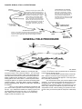
GROUND STEERING PRACTICE
For a couple of hours, practice taxiing the model around at low
speed. This is a very helpful step in making you feel more at
ease in controlling the model. Do not rush it. Use a parking lot
rather than a street where you are likely to run into a curb and
damage your model. Practice taxiing in light breezes or when the
air is calm; as strong or gusty winds can catch a wing and flip
your plane over. Apply minimum throttle that just keeps the model
moving at a walking pace. With the rudder stick and rudder trim
in neutral position, the model should move straight ahead. If it
constantly turns left or right, the nose wheel is not pointing
straight forward and should be adjusted by loosening the steering
arm.
When the plane is pointing at you, the steering will seem
"reversed." When you give right rudder, the plane turns to your
left-but the model actually is turning to its right. With practice,
you will become accustomed to this. When the model comes
toward you, simply push the stick left or right, in whichever direction the ship is turning. Another helpful technique is shown in
Sketch A. "Head-on disorientation" is dangerous in the air, where
things can happen pretty quickly. Before flying, it is wise to
spend some time familiarizing yourself with orientation by operating the controls, with the plane set on a table, while you view it
from different positions. The more familiar you become with the
behavior of the model as you control it on the ground, the better
prepared you will be for flying.
After taxi runs are completed, thoroughly examine the model and
tighten any loose screws, etc. First flights should be made on a
day that is not very windy or gusty. There should be very few
people or other distractions around; you will need to concentrate.
Your success doesn't depend on following the instructions here to
perfection, but you should have a flight sequence in mind. Think
ahead of the model ¾ don't chase it around the sky, always one
though and one control command behind it.
GENERAL FLIGHT TECHNIQUES
In flying, it is very important to make all your control movements
slow and measured. Rapid movements tend to throw the model
out of control. Try to make all turns gentle, not tilting (banking)
the wing very much. If you increase the bank, making the turn
steeper, there will be a corresponding weight increase and reduction of lift. Therefore, when you bank your plane, it will start to
descend. To maintain altitude in a turn, add enough back stick
(up elevator) to hold the nose "up" through the turn
37
FIRST FLIGHT
There is no way to fully explain the principals of flight and the
techniques of flying in a few pages. Entire books have been written about apparently simple subjects, such as the shape of the
wing. Furthermore, there is no substitute for an experienced R/C
flight instructor. The following information is not intended to
replace your instructor, but to help give you understanding of
basic flight concepts and techniques.
One of the most important, yet sometimes forgotten pre-flight
checks to always make sure the wing is securely banded to the
fuselage. Use at least seven #64 rubber bands on each side of
the wing.
NOW THAT YOU'RE READY...
It is important to have a total flight plan in mind. Look at the flying sketches here to get an idea of the take-off direction and
space you will need when flying at your field.
1.
Start your engine. Point the model directly into the wind
and advance the throttle smoothly, steering on the ground with
rudder. The plane will gain speed rapidly.
Remembering to operate the controls smoothly, add
slight back stick pressure, if necessary, to keep the model from
descending. When it is about 100 feet away from you, it will start
to gently climb. Be patient; let it climb slowly, as a steep climb
will cause it to stall. Most crashes are due to moving the controls
too much, so be slow and gentle on the controls during "climb
out" and throughout the flight. Over-controlling tends to throw the
plane out of control and wastes power. Just keep the model flying in a gentle 5° to 10° climb into the wind. Keep the wings level
until you have reached an altitude of about 150 feet.
2.
Patiently allow the model to slowly climb to 150-200
feet, adding just a touch of left or right aileron stick pressure until
the model begins a very shallow turn in the direction you want to
go.
38
Plan to make your first flight a short one. You will be surprised
how exhausting beginning flights can be. Plan to spend no more
than 2-3 minutes in the air the first few times you fly.
3.
Try to maintain this shallow turn. Do not let the turn get
too steep. The wind will tend to blow your plane further downwind. Try to keep it upwind at all times prior to your landing
approach. It is more difficult to fly a model when it is downwind,
and if a mistake is made, the model will end up further away,
making it harder to fly back to the field. To compensate for wind,
continue making upwind turns shallow, but make downwind turns
a little steeper.
The drawings on the next page illustrate some of the problems
that may occur in flight, as well as the proper corrective maneuvers.
DANGER: SPIRALS, STALLS, OVERSTRESSING
SPIRALS. As bank angle increases, more
back-stick is needed to keep flying level. If
the bank is too steep, the back-stick won't
be able to keep up and the plane will spiral
downward at increasing speed. Trying to
pull the model out of the spiral by pulling
back on the elevator only makes things
worse. This sequence of events happens
fast and can panic new flyers to the point
they fly the model right into the ground! TO
GET OUT OF THE SPIRAL, 1st LEVEL
THE WINGS., then pull it smoothly out of
the dive.
OVERSTRESSING THE AIRFRAME.
Even world class aerobatic competition
planes can be overstressed. This happens when controls are jerked when the
plane is flying at a high rate of speed. If
you find yourself in a high-speed dive,
immediately switch the motor off, level the
wings, and gently pull the stick back (add
up elevator) to recover.
STALLS. Your model's movement through the air keeps it flying. If you
fly too slowly, there is a point where the model will stop flying and fall out
of the sky. This is called a stall. Take care, when landing, to not slow
down too much
GENERAL FIELD PROCEDURE
FLYING A PATTERN
At most flying fields, models fly in a rectangular path
around the runway. This is called the "pattern." The most important reason for flying the pattern is that, as the model flies in different directions in the wind, the pilot will be better prepared for
landing conditions when the flight ends. Full-scale aircraft fly a
landing pattern for this same reason. Another important reason
for flying the pattern is to organize the take-off and landing traffic,
reducing confusion. The "traffic" pattern consists of PATTERN
ENTRY, DOWNWIND LEG, BASE LEG, AND FINAL APPROACH
& LANDING.
When you have reached an altitude of 150-200 feet, add
just a touch of left or right stick until the model begins a very shallow turn. Try to maintain this shallow turn, keeping it gentle, and
not tilting (banking) the wings very much. If you increase the
bank, making the turn steeper, there will be a corresponding
weight increase and reduction of lift
39
Therefore, your plane will start to descend. To maintain altitude
in a turn, you will have to add enough back stick (up elevator) to
hold the nose up through the turn.
Plan to enter the pattern upwind at about 150 feet altitude. Make the Downwind Leg far enough away to allow for
gentle turns to Base Leg and Final Approach. Avoid tight "panic"
turns, particularly when landing.
The wind will tend to blow your plane and pattern further
downwind. Try to keep it flying upwind at all times prior to your
landing approach. It is more difficult to fly a model when it is
downwind, and if a mistake is made, the model will end up even
further away, making it more difficult to fly back to the field. To
compensate for wind, continue making your upwind turns shallow, but make your downwind (with the wind) turns a little steeper.
LANDING
For your first landings, don't be concerned about trying to land in
a particular spot. Just land safely, without damage to your model.
At first, concentrate on flying in wide circles, as shown, and then
simply glide down straight into the wind.
With a 2-channel system, when the battery begins to run
out, the model will start a gradual descent. Continue circling and
start calculating how much longer the model will glide. After
imagining how much glide you have, you can start planning
ahead for landing.
For 3-channels, if you have a helper, he can time your flight and
tell when you have about four minutes of flight time. If you turn
the motor off at that point, there will be one or two minutes of battery power left.
With the power off and the plane gliding downward, plan
your approach for landing. When the model is about 45º downwind of the landing area, turn to Base Leg. Continue your
descent, letting the model slowly lose more altitude. (If you are
not happy with the approach, turn the power back on, climb out,
and set up for another pass.) Remember, "a good approach is a
good landing." Don't rush it.
For your FINAL APPROACH & LANDING, make a gentle turn to point the model in the direction of the landing area.
Keep the nose of the plane slightly down, so you don't stall.
Steer the plane into the wind as it glides, keeping the wing level.
Let the model settle in toward the ground and land. Just before
the model touches down, you can add just a bit of back stick (up
elevator) to "flare" and soften the landing.
Walk over to your plane and turn off the receiver first,
and then the transmitter. Congratulations! You've just completed
your first flight.
40
GROUND TAKE-OFFS
As you gain flying experience and confidence, you will
want to try to take off from the grass or runway. First, point the
model directly into the wind. Switch the motor on and gently
steer the model straight with rudder as the model gains speed
rapidly. After it rolls about 50-75 feet, add slight back stick ) up
elevator) pressure, so that the model rises smoothly from the
ground. Only hold as much back stick as necessary to keep the
plane in a 5º to 10º gentle climb. If you try to pull the model up
too steeply, it may slow down and then stall and crash.
SETTING ADJUSTMENTS
As you get used to the controls, you probably will notice the
model turning somewhat, or climbing or descending, without any
stick pressure on your part. These tendencies can be corrected
in the air by moving the trim tabs on the Tx. After landing, the
setting of the rudder or elevator should be similarly adjusted as
best you can by means of the clevises. This, in turn, permits the
Tx trim tabs to be re-centered. Further flights will show if more
adjustment is required. A severely out-of-trim condition (caused
by a warped wing, for example) might not be correctable using
the above trim techniques. In that case, taking the model home
and straightening the warp with heat is necessary.