1
ARF
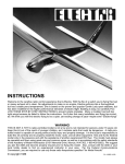
The Electra ARF sailplane was designed to be a gentle trainer for the beginning R/C modeler, yet possess an electric motor to so
that it can be flown almost any where. Electra ARF is a very efficient machine, she reacts quickly to rising air ( called lift, or
thermals) so that long flight times are easily achieved. Electra ARF can circle very tightly without falling off so stay in the thermal. . The Electra ARF has good penetration into the wind and can really “cruise” when desired. Before starting to build, read
through these instructions and familiarize yourself with this booklet.
If this is your first electric plane, then you will need make a decision. Do you want to turn on the motor and fly till the battery runs out of power (2 channel radio required)? Or do you want to use an electric speed control that will let you stop and
start the electric motor when you want too (3 to 4 channel radio required). Both methods are included in this booklet. You
will need to do some soldering of wires but the Electra ARF will perform great either way you build it.
WARNING
While this aircraft is an excellent first choice for novice pilots, a radio-controlled model is not a toy and is not intended for
persons under 16 years old. Keep this kit out of the reach of younger children, as it contains parts that could be dangerous. A radio-controlled model is capable of causing serious bodily injury and property damage. It is the buyer’s responsibility to build this kit correctly and to properly install the motor, radio, and all other equipment. Test and fly the finished
model only in the presence and with the assistance of another experienced R/C flyer. the model must always be operated and flown using great care and common sense, as well as in accordance with the Safety Code of the Academy of
Model Aeronautics (5151 Memorial Drive, Muncie, IN 47302), 1-800-435-9262). We suggest you join the AMA and
become properly insured prior to flying this model. Also, consult with the AMA or your local hobby dealer to find an
experienced instructor in your area. Per the Federal Communications Commission, you are required to use only those
radio frequencies specified “for Model Aircraft”.
CARL GOLDBERG PRODUCTS, LTD.
'Copyright 2003
P.O. Box 818 Oakwood, GA 30566 Phone # 678-450-0085 www.carlgoldbergproducts.com
Items needed to complete this kit. Necessary Tools and Supplies.
1 Radio Guidance system( 2 channel
Roll of waxed Paper
minimum required)
Modeling Knife and Single Edge Razor Blade
1 2oz. bottle CA glue
Pins
1 CA accelerator
Electric Drill
1 30 minute epoxy
1
Box #64 Rubber bands.
1
1/4 x 8 x 12” CGP Foam Padding
Various Drill Bit
Small Screwdriver
For Engine Power
Masking Tape
7 cell 1500 to 1900 mAh battery
30-60 Degree x 6” Triangle
Optional: C-20 ESC or C-30 Mini ESC speed control (Great
Planes MFG.)
Pencil
Selecting Radio Control
Equipment
Radio sets are battery powered with either dry cells or the more
reliable, rechargeable nickel-cadmium (ni-cad) batteries.
Although ni-cad powered units are more expensive, the cost of
routinely replacing worn out batteries may be much higher in the
long run. Many of the radio systems now available feature
“servo reversing” switches which allow you to reverse the
response of the servo. This simplifies radio installation and is
worth considering. Exponential or dual rates are popular features
which , if used properly, can help smooth out the flight of a sensitive model. Your local hobby dealer should be able to help you
select the proper radio for your needs and skill level. And be
sure to get a system designed for aircraft, as only certain frequencies are available for model aircraft.
Limited Warranty
Carl Goldberg Products takes pride in the care and attention
given to the manufacture of components for its model airplane
kits. The company warrants replacement of any materials found
to be defective for their intended use, prior to their use in construction of the aircraft, provided the buyers requests such
replacement within a 90 day period from the date of purchase
and provided the defective part is returned, if so requested by
the company.
No other warranty, expressed or implied, is made by the
company with respect to this kit. The buyer hereby assumes full
responsibility for the risk and all liability for personal or property damage or injury arising out of the buyer’s use of the components of this kit.
Important Information
Covering coming loose is not COVERED UNDER WARRANTY. Due to temperature
changes the plane may develop some wrinkles in the covering that you will need to
remove with an iron. Be sure to seal the edges down first so that you do not cause the
covering to shrink and leave exposed areas of wood. Please inspect the plane before
beginning to assemble to make sure you are happy with it. After assembly has begun you
cannot return the kit. If you find a problem before beginning to assemble the plane you
must contact us, please do not return it to the dealer.
2
Parts Identification
Using This Instruction Manual
Before you start gluing take some time to look through this entire
instruction booklet. It is designed to guide you through the construction process step by step, so build in the order given in this
book. Radio selection and installation , balancing and flying the
model are all covered.
Like a full-size airplane, the Electra ARF is built from basic
structures (stabilizer, fin, wing, etc.), which are then assembled
into the complete airplane.
Special procedures or comments will usually be explained before
a step, so you will be prepared. If a step begins with a statement
like “Note,” “Warning,” or “Important,” it is a good idea to read
through the step before doing it.
A check-off box appears at the beginning of each step. Check
these boxes as you build, so you can tell at a glance what steps you
have completed.
Some of the instructions deal with general procedures. Boxes are
not needed for these sections.
Right Wing Panel
Fuselage
Stabilizer (Stab)
Elevator
Fin
Rudder
Cowl
(2)
(2)
(4)
(2)
(2)
(2)
(2)
(1)
(1)
You will need a area approximately 18” x 80” in order to build
the Electra ARF. Place a sheet of waxed paper or plastic kitchen
wrap over the work area to prevent CA from sticking to your table.
Construction Tips
3
Canopy
Motor
Prop
Spinner
Additional Items included in the kit:
Preparing For Assembly
If you have never assembled a built-up model before, the following tips will prove helpful.
IMPORTANT: ALWAYS READ A FEW STEPS AHEAD. This
will alert you to coming instructions and will help you plan
accordingly.
You may find it convenient to empty all of the small parts from
the hardware bags into a common container, such as a margarine
tub. This will help you find items quickly.
When drilling any 1/16” holes in balsa, you may find it easier to
twist the drill between your thumb and index finger. This procedure allows more control in positioning the drill on the center
mark.
Left Wing Panel
Control Horns
Control Horn Bases
2-56 x 1/2” Pan Head Screw
Wire
Snap Links
Snap Link Retainers
Pushrod Connectors
Wood wing Joiner
Prop hub assembly
Wing Assembly
1.
Collect the following parts:
(1) Left wing panel
(1) Right wing panel
(1) Wing Joiner
2.
Holding the wing joiner with the angle cut facing up,
insert them into the joiner pockets in both wing
halves. The joiners should fit easily in the pockets
and the wing halves should meet in the middle, with
the wing dihedral forming a broad "V".
3.
Working on a protected surface, and with a paper
towel handy for cleaning fingers, THOROUGHLY
mix 1-2 large (soup) spoons each from bottle A and
bottle B of epoxy. (Use equal amount of each part
and mix with a stick in a plastic or paper cup, or on
a sheet of waxed paper.)
Spread the epoxy in the joiner pockets and in the
dowel hole and spread a thin layer of epoxy along
one side of the entire center joint area.
Immediately proceed to the next step.
4.
Working rapidly, so that the epoxy does not set
before you are finished, slide the wing joiner into
one wing pocket.
3.
Then slide the wing halves together until they are
touching. Make sure the rear dowel slides into the
dowel hole.
Trial fit the stab in place on the fuselage. Place a
piece of making tape across the fuselage in front of
were the stab mounts.
Measure across the fuselage and mark the center.
4.
Place two strips of masking tape along the edge of
the stab, next to the both outer stab tips and above
the hinge line.
Using a T-square or triangle, draw a line from the
front center point of the stab to the rear hinge line.
5.
Measure 9-1/2” out ("B") from each side of the centerline and make a mark on the masking tape.
With masking tape, tape the wing halves together at
the trailing edge and close to the leading edge, as
shown. This will help keep the wing from twisting.
5.
Place additional tape at several locations across the
center seam of the wing, so that the halves stay
firmly together while the epoxy sets.
Measure from the marks on the stab to the polyhedral breaks on the wing adjust as necessary to line
up with wing.
Mark the stab and fuse with matching line-up points.
Allow the epoxy to dry thoroughly.
Note: Both outer wing tips should be about
6-3/8” off the table top.
Stab Assembly
7.
1.
Make sure the stab is level (parallel) with the wing
and insert paper strip shims, if necessary.
Collect the following parts:
(1)
(1)
(1)
(2)
(4)
Fuselage
Stabilizer
Fin
Control Horn
Screws
Elevator Mark
1.
8.
Mount the wing on the fuselage using the rubber
bands provided
Turn over the plane and mark the area on the bottom of the stab where it rests on the fuse.
Measure carefully from the fuse sides out to the
polyhedral breaks (arrows ‘A’) to be sure that the
wing is centered.
2.
When satisfied with the alignment of the stab, temporarily tape securely in place.
Now measure from the polyhedral to the back end
of the fuselage(arrow ‘B’) to make sure wing is
square to the fuselage.
Mark the wing and the fuselage with matching lineup points.
4
Remove the stab from the fuse and, working 1/4"
inside the drawn lines, carefully remove the covering from the bottom of the stab. BE CAREFUL TO
AVOID CUTTING THE WOOD
Remove the rudder from the fin and set to the side.
Mark the center of the elevator and remove the elevator from the stab
9.
Spread epoxy on both the bottom of the stab and
the stab platform of the fuse.
Replace the stab on the platform and, after again
checking the alignment of the stab to the wing, allow
the epoxy to dry thoroughly.
2.
Slide the fin mounting posts into the top of the stab.
Check the fit. The fin should fit easily into each slot
and should stand upright by itself. Enlarge the
holes, if necessary.
3.
4.
Place the control horn on the bottom of the elevator
over the center mark you made.
As shown above, mark where the fin touches the
fuselage.
Mark the screw hole locations.
Drill the holes for the control horn.
Using two machine screws, secure the control horn
to the elevator.
Fin Assembly
1.
TAKING CARE NOT TO CUT INTO THE WOOD
STRUCTURE UNDERNEATH, and working inside
the drawn lines, carefully remove the covering
where the fin mounts on the fuse and stab.
Collect the following items:
(1)
(1)
(1)
(2)
Fin
fuselage
Control Horn
Screws
5.
4.
With the rudder sitting on the fin, as shown, place
the horn on the bottom of the rudder.
Mark the holes.
Drill the holes for the control horn.
Again using two machine screws, secure the control
horn to the rudder.
5
Remount the fin on the fuse and, using a 90º triangle, make sure the fin is perpendicular to the stab.
When satisfied with the fit, remove fin and mix up a
couple of spoonfuls of epoxy.
Apply a THIN, even coat of epoxy on the bottom of
the fin and along both sides of the fin mounting
posts. Avoid too much glue, which will squeeze out
from underneath the fin.
Mount the fin on the fuse and place the triangle
against the fin to make sure it is perpendicular.
Use masking tape to secure the fin and triangle in
position until the epoxy is thoroughly dry. Make sure
not to glue the triangle!
Mounting Rudder and
Elevator
1.
Installing the Radio
1.
(2)
(2)
(1)
(2)
(2)
(2)
Collect the following items:
(1)
(1)
(1)
(2)
(7)
Collect the following items:
Rudder with control horn
fuselage
Elevator with control horn
long wire with “Z” bends
Hinges
Servos with screws(Supplied with Radio)
Servo Arms
fuselage
Pushrod connector
Nylon Snap Nut
Set Screws
Elevator Servo
Nose
Rudder Servo
1.
Mount your servos as shown above.
Set Screw
Push Rod Connector
1.
Remount the the hinges back into the rudder. Place
one of the long wires onto the control horn using the
“Z” bend.
Cut Off Extra Arms
Nylon Set Nut
2.
Insert the Pushrod connector through the hole on
the servo arm and install the snap nut on the bottom
as shown above.
3.
Slide the rudder pushrod wire through the hole and
mount the servo arm on the rudder servo.
Hint: Do not screw the servo arm on the servo at
this time.
Rudder Pushrod
Exit Hole
Repeat steps 2 and 3 for the elevator servo arm.
4.
2.
Insert the wire into the hole on the top of the fuselage and slide the wire down into the tube.
3.
Insert the hinges into the slots of the fin.
Place tape on both the elevator and the rudder to
hold them both straight and level to the fin and stabilizer.
Hint: Place a pin in the center of the hinge so that
the hinge will insert half way into the fin and the rudder.
When satisfied with the fit then place one drop of
thin CA glue on each side of all the hinges. Remove
the pins and set aside for about 10 minutes.
Repeat this process for the elevator. DO NOT FORGET THE PUSH ROD WIRE.
Making sure that the servo arms are as shown
above. Insert the set screw into the top of the
pushrod connecter and tighten onto wire.
Rear of Fuselage
5.
Elevator
Pushrod
Exit Hole
6
Place the receiver in the front of the servos.
Plug the servos into the receiver as shown in
your radio instructions.
Installing Motor Switch
Note: We recommend that you use a electric
speed control for your electra. You will get
better performance and have more control
over the airplane while flying.
The following steps are for 2 channel operation. This will allow you to run the motor till the
battery runs out of power.
20 Amp Fuse Here
1.
Your Electra ARF comes with a 20 amp fuse in
the wire that runs from the battery plug and the
motor. This fuse will prevent the motor from
being damaged by any obstruction that might
stop the propeller from turning.
4.
Carefully cut through the side of the fuselage
and mount your receiver switch as shown.
Plug the switch into the receiver as shown in
your radio instructions.
2.
Slide the motor wires from the front through
the forward former.
Press the motor down into the motor tray.
Wrap 2 rubber bands around the motor.
Wrap the receiver and the battery pack in foam
and place in the nose. Plug the battery into the
switch.
The motor system is designed with a safety fuse to protect the system from excessive motor loads. During
motor operation, if the propeller should hit an object, the
sudden surge of battery current will blow the fuse and
prevent motor/battery burn out or other damage. Use
only a 15 or 20 AMPfuse to connect the fuse terminals.
DO NOT BY-PASS THE FUSE or directly connect the
terminals together. If using another brand of motor,
make sure it is equipped with a fuse. If it isn’t, ask your
hobby dealer how to install one. DO NOT OPERATE
YOUR ELECTRA MOTOR SYSTEM WITHOUT A
FUSE!
Operate motor ONLY with propeller securely installed.
Without propeller, the motor may “over-rev” and be permanently damaged.
Make sure that the amount of movement you
have for both the elevator and the rudder does
not exceed the following measurements for the
first flight.
3.
Drill a hole into the side of the fuselage and
mount the motor switch.
NOTE: If you will launch the plane using your right
hand, mount the motor switch on the left
side of the fuselage.
7
Elevator
5/16” up and down
Rudder
1” right and left
The following steps are for 3 channel operation. This will allow you to control the motor till
the battery runs out of power. This also alleviates the need for a separate receiver battery
pack.
We will be showing the installation of Great
Planes ElectriFly C-30 Mini ESC. Follow the
instructions that come with your speed control
to assure proper installation.
BATTERY HAZARD!
The battery size used to power the Electra ARF motor
stores a lot of electrical energy. Be careful to prevent
shorting it out. A dead short can cause a powerful surge
of electrical current which can ruin your battery and generate enough heat to start a fire. It can also cause burns
to you and others.
The motor/battery system used to power the Electra
ARF is very powerful. To avoid injury, always disconnect
and remove the motor battery when you are not flying
the airplane.
1.
Remove both wires from the back of the
motor.
PROPELLER HAZARD!
When switched on, the motor instantly reaches full
power and maximum propeller RPM. An electric motor
pulls more battery energy as its work load is increased.
This means, for example, that if the prop hits your
hand, it not only smacks you at high speed, it also
draws more battery power to overcome the added
load. Therefore, the impact force and injury are
increased. It is extremely important that you are aware
of these dangers and take precautions to prevent accidentally switching on the motor. This is especially
important while working on the model or when storing
it. Always remove the battery when storing the model
and make sure it is kept away from children and anyone else who is not familiar with its safe operation.
Follow the instructions that came with your
particular speed control at this time.
IMPORTANT!
PLEASE READ THIS SECTION
FAILURE TO FOLLOW THESE PRECAUTIONS CAN
LEAD TO SERIOUS PERSONAL INJURY TO YOURSELF OR OTHERS, AND CAN RESULT IN PROPERTY DAMAGE.
REMEMBER: ALWAYS DISCONNECT AND
REMOVE BATTERY WHEN WORKING ON THE
MODEL, TRANSPORTING, OR STORING IT. DO
NOT LEAVE THE BATTERY CONNECTED EXCEPT
WHEN FLYING!
SAFETY PRECAUTIONS:
WHEN OPERATING THE MOTOR:
ALWAYS wear eye protection!
KEEP AWAY from spectators!
KEEP AWAY FROM CHILDREN. DO NOT allow
children to operate without adult supervision.
PROPELLER must be properly installed to prevent excessive RPMs.
MOTOR BATTERY SHOULD BE DISCONNECTED except when ready to fly or when necessary for checking electrical operation and
maintenance.
OPERATE MOTOR ONLY WITH PROPELLER
INSTALLED.
8
Radio Layout
Installing Cowl and Prop
#4 SET SCREW
LARGE WASHER
3.
1.
Place the cowl on the nose of the fuselage. Try
to keep the bottom of the cowl as close to the
bottom of the fuselage.
Thread a #4 socket set screw in the prop
mount and turn a few times.
Open the spinner supplied by carefully inserting a small screwdriver straight into each of the
slots. DO NOT TWIST! JUST PRY OPEN.
NOTE: Carefully read the instructions included with
your spinner.
When the spinner backplate has been
removed, place it on the propeller mount.
Using a 1/16” drill, make 2 holes on both sides
of the cowl. Try to drill into the side of the front
former.
DO NOT OVER TIGHTEN
PIN
4.
2.
Using #2 x 3/8” screw, mount the cowl on the
fuselage.
9
Place the propeller on top of the backplate so
that it lines up with the pin, as shown above.
Place a large washer on top of the prop and then
install, using a #4 x 1/2” machine screw. CAUTION: DO NOT OVER-TIGHTEN, as this may
cause the threads to strip out.
ALLEN
WRENCH
5.
Warning: A spinning propeller
can cause injury. Wear safety
glasses and operate away
from spectators.
Align the spinner cone with the prop/backplate
and press pins firmly into the holes. One way to
do this is to have the cone pointing downward on
a table and press until all pins are seated.
Install the prop/spinner assembly on the motor
shaft and securely tighten the set screw with a
.050 Allen wrench.
Canopy and Battery Hatch
3.
Insert the battery hatch into the bottom of the
fuselage. The tongue on the hatch goes forward.
In the rear of the hatch drill a 1/16” hole in the
middle.
Screw the hatch to the fuselage by using a #2
x 3/8” screw.
1.
Find the holes on the side of the fuselage and
cut a “X” pattern in the covering over the holes.
You will find two holes on each side of the
fuselage.
4.
Remove the hatch from the fuselage and carefully cut out each of the air holes
Note: Reinforce the hatch with small sticks if
using 7 cell batteries
NOTE: The air holes let the battery cool for better
performance.
2.
Insert a dowel into the front and back hole till
equal amounts are showing on both sides of
the fuselage.
When satisfied glue the dowels in place.
5.
10
Slide the canopy under the cowl. The rear of
the canopy will sit on top of the wing with the
rubber bands holding the wing will also hold
the canopy.
BALANCING ( Center of Gravity)
While the wing is rubber banded in place on the fuselage measure back from the
leading edge of the wing 3-1/2” to 3-3/4” to find the center of gravity.
With everything installed, mount the wing and carefully
check the Center of Gravity (CG). One way is to perch the
model on the thumb and forefinger of your left hand (if
you’re right handed), while steadying the model with the
other. A much better way is to use a balancing set-up,
which can be made with a couple of 1/4” dowels with
rounded tops, spaced just enough apart to clear the fuse.
Mark the desired CG on the underside of the wing, and
then set the model on the dowels at that location. Add
weight if necessary for balance. The least weight is
needed when added as far forward or back as possible.
DO NOT attempt to fly the model with the CG EVEN
SLIGHTLY BEHIND the rearmost recommended
position.
RADIO CHECK
Before going to the field to fly, with batteries fully
charged, turn on receiver and transmitter and actuate all
controls many times until you are satisfied with all
functions.
Prior to the beginning of each day’s flying, make a
range check of your equipment in accordance with the
collapsed, you should have at least 100 feet range on the
ground. To check this, set the model facing away from
you, turn on both the transmitter and receiver switches, and
walk away while transmitting signals. Watch to see that no
signals are missed until you are at least 100 feet away. Do
not attempt any flights unless the equipment works perfectly.
Be careful not to use your transmitter when someone
else on the field is flying or testing on the same frequency.
manufacturer’s instructions in general, with antenna
11
MOTOR & BATTERY MAINTENANCE & CHARGING
At the very quick charge rate that is common with
today’s field charger's, there is little room for error.
When you over-charge a battery, the temperature rises
quickly and there is potential for EXPLOSION, or at
least battery damage (Figure B). There are numerous
ways to prevent this. How you charge depends on the
type of charger you use.
IMPORTANT! THIS SECTION CONTAINS MATERIAL ESSENTIAL TO YOUR SAFETY AND THE MAXIMUM PERFORMANCE OF YOUR ELECTRA!
Please take the time to read this section very carefully. If you don’t understand, read again or get help from
an experienced electric pilot.
IMPORTANT! ALWAYS ALLOW THE BATTERY TO
COOL BEFORE CHARGING.
FIG. C
The Turbo 550 is a special motor designed for electric
plane use on 6-cell 1200 MAH nicad battery packs.
This battery is commonly used with 1/10 scale “off
road” electric cars and is therefore readily available. 7cell batteries also may be used and give a better climb
rate, but this will produce a shorter engine run and the
motor will run hotter. See figure A below.
TYPES OF CHARGER'S
Basic Charger with a Timer. To prevent an overcharge, you must know how full the battery is. A new or
nearly empty battery should receive a full charge, per
the instructions that come with the battery. This is usually about 15-minute charge (at 4.5 AMPS, if you have
an ammeter.)
FIG. A
During the last 5 minutes, lightly and carefully touch
the battery several times (ever minute or so). If it is
slightly warm, that is OK. If it is hot to the touch, that
signals that it is overcharged. STOP CHARGING
IMMEDIATELY! Allow the battery to cool to room temperature (usually 15-20 minutes) before using.
MOTOR
If you don’t know how full your battery is, set your timer
for no more than 5 minutes and monitor the temperature by lightly touching the battery every 1-2 minutes.
When the temperature starts to rise, the battery is fully
charged. Stop immediately (Figure C).
The motor is ready-to-use;just install as shown and be
sure there is enough ventilation around the motor for
adequate cooling. After a few flights, you should notice
a small increase in power, as the motor “breaks in.”
You may also wish to experiment with other propellers,
but we recommend you stay in the 8-4 size range.
FIG. D
FIG. B
If you have a digital volt meter, it can be very useful in
detecting when the battery reaches a full charge. As
the battery fills, the voltage goes up. When it’s fully
charged, the voltage will stop rising and in a minute or
two, as the battery temperature rises, the voltage will
drop slightly. As soon as it drops, stop charging. This
is an excellent way to get maximum batter performance. (Figure D.)
BATTERY
This section is particularly important! One way to
think of a battery charging is to imagine the battery as
a bucket and electricity as water. What you are trying
to do is to fill up the bucket (battery), but not overfill it.
12
“TREAT YOUR RADIO RIGHT AND IT WILL DO
THE SAME FOR YOU!” by Hal deBolt
Today's RC systems are very well engineered and
constructed. However, they will remain only as good
as the way in which they are USED. Always follow the
rules of proper usage and all manufacturer's instructions for your particular piece of equipment.
TRANSMITTERS: Keep your transmitter clean and
free from fuel residue and dirt. Battery condition and
RF output should be monitored, and the system
should be aligned and tuned annually. Do not transport under vibration (such as on the floor of a car) without cushioning.
Automatic Charger's. DELTA or PEAK DETECTION
CHARGER'S are excellent methods of charging a battery, as one simply connects the charger, pushes the
start button, and waits. Within approximately 15-30
minutes, the battery may be disconnected and used.
It is still a good idea to monitor the battery temperature
(by lightly touching) every minute or so after 10 minutes of charging. If you suspect the battery is overcharging, STOP IMMEDIATELY!
RECEIVERS: Receivers must be vibration free. When
installing in the aircraft, wrap them in a minimum of ¼"
soft foam rubber (not plastic foam). Keep well clear of
all cables and batteries. Tune annually (or as recommended by the manufacturer), as indicated below
under "Check-Ups."
TEMPERATURE SENSITIVE (THERMAL)CHARGER'S also work well, although they are more expensive the other charges described. The thermal charger
charges a battery pack in approximately 15-20 and it
doesn’t matter how full the pack is charging begins.
This charger “senses” when the battery temperature
signals a full charge and automatically stops charging.
However, the battery must be absolutely cool when
charging begins, or the charger will cut off prematurely.
SERVOS: Servos are vibration prone. Be sure to
mount them with grommet shock mounts in servo trays
which are also shock mounted. Also be sure to keep
them clean. If the neutral position "drifts," this is a sign
of change which should not be ignored; find out WHY
before flying again.
BATTERIES: Nicads also can suffer from vibration, so
they too should be wrapped in soft foam rubber before
installing. Check their condition periodically by measuring the voltage with a volt meter or battery tester.
Charge the batteries before EVERY flying session.
When not used for a period of time (such as during the
winter months) the batteries should be charged every
30 days. Never store batteries in a discharged condition.
Follow the manufacturer’s instructions carefully
when using any type of charger.
BATTERY EQUALIZATION
Any battery that hasn’t been used for a week or more
should be equalized for best performance. This is
done by charging the battery for 10-20 minutes at the
indicated rate and then giving the battery a trickle
charge for three to four hours. Refer to the charger
instructions for the recommended trickle charge technique. Equalizing the battery will assure top performance every time.
PUSHRODS: Obviously, pushrods should be installed
to operate freely, so that they place no load on the
servo. Using a servo's power to move a tight rod or
heavy surface by force increases the battery drain,
shortens the electronic life, and can cause neutralizing
problems. In addition, it is important the pushrods do
not flex or vibrate. Any vibration is transferred directly
to the servo, and its gear, motor, and pot. To avoid flexing and vibration, use guides and fairleads on the rods.
HOW MANY BATTERIES ARE NEEDED?
To get in the most flying at each session, we suggest
you purchase three battery packs. While one pack is
cooling and waiting to be charged, a second pack can
be on the charger, and the third pack can be in the
plane and ready to fly. With only one battery pack,
there may be up to a 40-minute wait between flights.
CONNECTORS: In using connectors, never pull on
the wires to disconnect; grasp the plugs instead.
Clean them by dunking in a solvent, such as dope thinner. Tape the connectors together when installing and
make sure there is no strain on the cables.
CHECK-UPS: A full check-up by the factory or an
authorized service center should be done AT LEAST
ONCE A YEAR, as well as any time something unusual occurs during usage. A malfunction or "glitch" is the
first sign of an impending failure; it should not be
ignored. The checkup should include tuning and alignment of the system, as well as battery testing.
13
FLYING THE ELECTRA
snugged down, receiver and battery wrapped in foam
rubber, etc. Prop and spinner must be tight. The receiver antenna must be extended, not coiled up inside the
model. Nothing should be loose, or unfinished, or
unchecked.
LEARNING TO FLY
Flying R/C is both fun and challenging. As with other
portions of this book, the following section is meant to
introduce you to the basics. Read carefully before taking your model out to the field and attempting first
flights. And remember, becoming an R/C pilot takes
time and patience, but the rewards are well worth the
effort.
With everything ready, the motor should be started for a
short time. While the motor is running, make sure the
control surfaces do not jitter or move until you command
them and that the motor switch also responds properly to
your command.
CGM SUPERTOTE
With transmitter and receiver switched on, hand launch
the model directly into the wind. Gently correct the flight
path as necessary. If any adjustments are needed to
maintain straight and level flight, get experienced help to
move the clevises.
Equipment Checklist
Flight batteries, fully charged
Extra battery packs
Radio transmitter
Battery charger
Tools for tightening any parts that can vibrate and
loosen
Extra #64 rubber bands
Extra props and an extra spinner
Prop wrench
Bottle of Super Jet™
In flight control. most of the beginner's trouble comes
from over-controlling or holding a signal too long. It is
better to operate your transmitter slowly and smoothly.
A troublesome tendency is letting the model get downwind. New flyers should try to keep the model upwind at
all times prior to the landing approach.
If you are a novice, seek the help of an experienced flyer.
Do not hesitate to ask one of the better flyers at the field
for help. Usually, they are glad to spend a little time to
get somebody started right, and they very likely were
helped in the same manner themselves.
WHERE TO FLY
CHECK YOUR EQUIPMENT
Prior to going to the flying field, with radio batteries fully
charged, turn on both receiver (Rx) and transmitter (Tx)
and actuate all controls many times until you are satisfied with all functions.
Before beginning each day's flying, make a range check
of your equipment in accordance with the manufacturer's instructions. In general, with transmitter antenna
collapsed to 6"-8", you should have an at least 100 foot
range on the ground. To check this, turn on both the
transmitter and the receiver switches, set the model
heading away from you, and walk away while transmitting signals to move the control surfaces. Watch to see
that no signals are missed until you are at least 100 feet
away. Only if the equipment works perfectly should any
flights be attempted. Again, be careful to not use your
transmitter when anyone else at the field is flying or
testing on the same frequency!
After the range check, stand behind the model and
make sure the control responses are correct. Moving
the control stick to the right should give right rudder (on
a 3-channel set-up) . Moving the stick back or down on
the Tx should move the elevator up, and vice versa.
Finally, make sure that everything on your aircraft is
neatly and firmly in place-motor fastened down, servos
14
Fly only in areas sanctioned for R/C and known to be free
of radio interference. Ask your hobby dealer or other
modelers if there is an R/C flying field that is used by a
local R/C club. This is the ideal place to fly. If you don't
know of an R/C club nearby, contact the Academy of
Model Aeronautics (AMA), at the address on the front of
this booklet, for information on a club in your area.
Remember: R/C flying fields need to have rules to help
prevent accidents, so ask about them before you turn on
any of your equipment! DO NOT TEST your transmitter in the parking lot or anywhere nearby until you
are sure no one else is using your radio frequency.
This could cause another flyer to crash and make
you very unpopular!
If there is no club or other R/C flying site available, locate
a square area (preferably a grassy field), at least four or
five football fields long, which is free of power lines,
trees, poles, houses, busy streets and other obstructions. It must be at least three miles away from any
areas where other R/C models, such as boats or cars,
are operated. It should also have a relatively smooth
surface, as it will take practice to learn precision landings. If you find a suitable location, turn your receiver on
for 2 or 3 minutes to check that no one in the vicinity is
operating an R/C device which could affect your receiver
and cause your plane to crash.
The Electra was designed for long, slow, relaxed flying not loops or similar aerobatic maneuvers. Save that kind
of lying for your next, higher performance sport plane.
Practicing precise control and glide planning on the
Electra is good preparation for the demands of advanced
aerobatic flying.
with wing level. With practice, you will be able to plan
your approaches to land just about where you want.
HAND LAUNCHING
We recommend you use 3 channels, as this will allow
you to cut power whenever you wish to do so. On your
first few flights, after a couple of minutes, you may feel
you have "had enough" and want to land and relax. A 2channel system without motor control will not give you
this option; you will have to keep flying until the battery
power runs down.
You can expect a good solid 4 or 5 minutes of powered
flight with a properly charged battery. In this amount of
time, Electra will gain several hundred feet of altitude and
will allow you time to get oriented and familiar with the
control "feel." When the battery power begins to run out,
climb will slow down and the model will begin a slow
descent. You should continue flying your same flying
pattern as the model slowly glides.
The Electra must be hand launched. This is easy to do,
but must be done carefully to avoid damaging the
model. It is best to launch over some tall grass. Facing
INTO the wind, hold the transmitter in one hand, the
model in the other and raise it above your head. The
wings should be level and the nose pointing straight
ahead-not slightly up. Imagine that you are gliding it
towards a spot about 50 feet ahead. DO NOT throw the
model UP. It's a natural tendency, but it will make the
model stall (fall) and dive to the ground.
For your initial landings, you should not be concerned
about trying to land at a specific spot. Your prime concern should be a controlled landing, always into the wind,
DOWNWIND TURNS A LITTLE STEEPER
3
UPWIND TURNS SHALLOW
2
1
After checking all controls, seeing that the Tx trim tabs
are centered, and making sure the Tx meter registers in
the safe zone, turn on the motor and hand launch the
model into the wind. Immediately take the Tx in both
hands and, remembering to operate the controls smoothly, begin to direct the model in a gentle climb. Add slight
back stick pressure, if necessary, to keep the model from
descending. Soon, when it is about 100 feet away from
you, it will start to climb. Be patient; let it climb slowly. If
the climb is too steep, the model will stall and fall to the
ground. Avoid over-controlling.
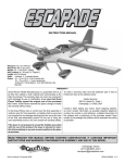
CLIMB OUT SHOWN HERE IS
EXAGGERATED. ACTUAL CLIMB
OUT IS QUITE SHALLOW.
reach an altitude of at least 150 feet.
STARTING THE PATTERN 2. At 150-200 feet of altitude, add just a touch of left or right stick pressure until
the model begins a very shallow turn in the direction you
want to go. 3. Try to maintain this shallow turn. The
wind will tend to blow your plane and the pattern further
downwind. Try to keep it flying upwind at all times prior
to your landing approach. It is more difficult to fly a
model when it is downwind, and if a mistake is made, the
model will end up further downwind, making it more difficult to fly back to the field. To compensate for wind,
continue to make upwind turns shallow, but make the
downwind turns a little steeper.
CLIMB OUT. 1. During the climb out, just try to keep the
model flying into the wind with the wings level until you
15
to fly a model when it is downwind, and if a mistake is
made, the model will end up further downwind, making it
more difficult to fly back to the field. To compensate for
wind, continue to make upwind turns shallow, but make
the downwind turns a little steeper.
When the plane comes toward you, the steering will
seem reversed. When you give right rudder, the plane
turns to your left, but it is actually turning to its right. With
practice, you will soon get used to this. (It’s a good idea
to practice using the controls with the model sitting on a
table before you actually begin flying.) Simply push the
stick left or right towards whichever way the ship is turning. A helpful technique is shown in the above sketch.
You may feel less disoriented and better able to control
the model by facing in the same direction as the plane is
flying and looking over your shoulder.
As you get used to the controls, you probably will notice
the model turning somewhat to the left or right, or climbing or descending, without any stick pressure on your
part. These tendencies can be corrected in the air by
moving the trim tabs on the Tx. After landing, get an
experienced flier to help adjust the setting of the rudder
or elevator by adjusting the mini-snaps (clevises). If the
wing or other structures have become warped, it is best
to discontinue flying and take the model home to straighten it.
If flying with a 2-channel system, when the battery begins
to run out, the model will start a gradual descent. If flying
a 3-channel system, it’s good to have a helper to let you
know when you have been flying for about four minutes.
Then you can turn the motor off and have about one or
two minutes of battery power left. If you are not happy
with your first approach, you will then be able to restart
the motor and set up another pass.
4
5
6
LANDING
4. Continue your pattern and try to determine how much
longer the model will glide. Start planning for the landing. With the power off, you will get used to the model’s
glide. 5. Try to plan your approach so that the model is
about 100 feet high and ready to complete the downwind
portion of your pattern. 6. Continue making a shallow
turn, bringing the plane around until you have it pointed
directly into the wind. Be patient and keep your glide
steady and gentle, with the wings level. 7. A controlled
landing into the wind is your prime concern. Don’t worry
about trying to land the model near you when you are
16
first learning to fly. It is better to walk a few blocks to
recover a whole airplane than to pick up pieces at your
feet! Just before the model is ready to touch down, you
can add just a touch of back stick pressure to “flare” the
landing. Retrieve your plane and switch off first the
transmitter and then the receiver.
Take things slow and easy and you’ll be able to enjoy flying your Electra for years to come.