1
WN-300ARM-VPN
11n ADSL2/2+VPN Router
User’s Manual
Declaration of Conformity
We, Manufacturer/Importer
OvisLink Corp.
5F., NO.6, Lane 130, Min-Chuan Rd.,
Hsin-Tien City, Taipei County, Taiwan
Declare that the product
11n ADSL VPN Router (Annex A / Annex B)
AirLive WN-300ARM-VPN
is in conformity with
In accordance with 1999/5 EC-R & TTE Directive
Clause
Description
■ EN 300 328 v1.7.1
Electromagnetic compatibility and Radio spectrum Matters (ERM)
Wideband transmission equipment operating in the 2.4GHz ISM band
And using spread spectrum modulation techniques; Part 1:technical
Characteristics and test conditions Part2:Harmonized EN covering
Essential requirements under article 3.2 of the R&TTE Directive
(2006-10)
■ EN 301 489-1 V1.6.1
Electromagnetic compatibility and Radio spectrum Matters (ERM);
(2005-09)
Electromagnetic compatibility(EMC) standard for radio equipment and
■ EN 301 489-17 V1.2.1 Services; Part 17:Specific conditions for wideband data and
(2002-08)
HIPERLAN equipment
■ EN 50385:2002
Product standard to demonstrate the Compliance of radio base
stations and Fixed terminal stations for wireless Telecommunication
System with the Basic restrictions or the reference levels related to
human exposure to radio Frequency electromagnetic fields ( 110 MHz
– 40 GHz ) - General public
■ EN 60950-1:2001/A11 Safety for information technology equipment including electrica
:2004
business equipment
■ CE marking
Manufacturer/Importer
Signature
:
Name
: Albert Yeh
Position/ Title: Vice President
(Stamp)
Date: 2008/11/20
AirLive WN-300ARM-VPN CE Declaration Statement
Country
cs
Česky [Czech]
Declaration
OvisLink Corp. tímto prohlašuje, že tento AirLive
WN-300ARM-VPN je ve shodě se základními
požadavky a dalšími příslušnými ustanoveními
směrnice 1999/5/ES.
da
Dansk [Danish]
Undertegnede OvisLink Corp. erklærer herved, at nl
Nederlands [Dutch
følgende udstyr AirLive WN-300ARM-VPN
overholder de væsentlige krav og øvrige
relevante krav i direktiv 1999/5/EF.
Hierbij verklaart OvisLink Corp. dat het toestel AirLive
WN-300ARM-VPN in overeenstemming is met de
essentiële eisen en de andere relevante bepalingen
van richtlijn 1999/5/EG.
de
Deutsch
[German]
Hiermit erklärt OvisLink Corp., dass sich das
mt
Malti [Maltese]
Gerät AirLive WN-300ARM-VPN in
Übereinstimmung mit den grundlegenden
Anforderungen und den übrigen einschlägigen
Bestimmungen der Richtlinie 1999/5/EG befindet.
Hawnhekk, OvisLink Corp, jiddikjara li dan AirLive
WN-300ARM-VPN jikkonforma mal-ħtiġijiet essenzjali
u ma provvedimenti oħrajn relevanti li hemm
fid-Dirrettiva 1999/5/EC.
et
Eesti [Estonian]
Käesolevaga kinnitab OvisLink Corp. seadme
AirLive WN-300ARM-VPN vastavust direktiivi
1999/5/EÜ põhinõuetele ja nimetatud direktiivist
tulenevatele teistele asjakohastele sätetele.
Az OvisLink Corporation kijelenti, hogy az AirLive
WN-300ARM-VPN megfelel az 1999/05/CE irányelv
alapvető követelményeinek és egyéb vonatkozó
rendelkezéseinek.
en
English
Hereby, OvisLink Corp., declares that this AirLive pl
Polski [Polish]
WN-300ARM-VPN is in compliance with the
essential requirements and other relevant
provisions of Directive 1999/5/EC.
Niniejszym OvisLink Corp oświadcza, że AirLive
WN-300ARM-VPN jest zgodny z zasadniczymi
wymogami oraz pozostałymi stosownymi
postanowieniami Dyrektywy 1999/5/EC.
es
Español
[Spanish]
Por medio de la presente OvisLink Corp. declara pt
que el AirLive WN-300ARM-VPN cumple con los Português
requisitos esenciales y cualesquiera otras
[Portuguese]
disposiciones aplicables o exigibles de la
Directiva 1999/5/CE.
OvisLink Corp declara que este AirLive
WN-300ARM-VPN está conforme com os requisitos
essenciais e outras disposições da Directiva
1999/5/CE.
el
ΜΕ ΤΗΝ ΠΑΡΟΥΣΑ OvisLink Corp. ΔΗΛΩΝΕΙ
Ελληνική [Greek] ΟΤΙ AirLive WN-300ARM-VPN
ΣΥΜΜΟΡΦΩΝΕΤΑΙ ΠΡΟΣ ΤΙΣ ΟΥΣΙΩΔΕΙΣ
ΑΠΑΙΤΗΣΕΙΣ ΚΑΙ ΤΙΣ ΛΟΙΠΕΣ ΣΧΕΤΙΚΕΣ
ΔΙΑΤΑΞΕΙΣ ΤΗΣ ΟΔΗΓΙΑΣ 1999/5/ΕΚ.
Country
lt
Lietuvių
[Lithuanian]
hu
Magyar
[Hungarian]
sl
Slovensko
[Slovenian]
Declaration
Šiuo OvisLink Corp. deklaruoja, kad šis AirLive
WN-300ARM-VPN atitinka esminius reikalavimus ir
kitas 1999/5/EB Direktyvos nuostatas.
OvisLink Corp izjavlja, da je ta AirLive
WN-300ARM-VPN v skladu z bistvenimi zahtevami in
ostalimi relevantnimi določili direktive 1999/5/ES.
fr
Par la présente OvisLink Corp. déclare que
sk
OvisLink Corp týmto vyhlasuje, že AirLive
Français [French] l'appareil AirLive WN-300ARM-VPN est conforme Slovensky [Slovak] WN-300ARM-VPN spĺňa základné požiadavky a
aux exigences essentielles et aux autres
všetky príslušné ustanovenia Smernice 1999/5/ES.
dispositions pertinentes de la directive 1999/5/CE
it
Italiano [Italian]
Con la presente OvisLink Corp. dichiara che
fi
questo AirLive WN-300ARM-VPN è conforme ai Suomi [Finnish]
requisiti essenziali ed alle altre disposizioni
pertinenti stabilite dalla direttiva 1999/5/CE.
lv
Ar šo OvisLink Corp. deklarē, ka AirLive
Latviski [Latvian] WN-300ARM-VPN atbilst Direktīvas 1999/5/EK
būtiskajām prasībām un citiem ar to saistītajiem
noteikumiem.
sv
Svenska
[Swedish]
OvisLink Corp vakuuttaa täten että AirLive
WN-300ARM-VPN tyyppinen laite on direktiivin
1999/5/EY oleellisten vaatimusten ja sitä koskevien
direktiivin muiden ehtojen mukainen
Hér með lýsir OvisLink Corp yfir því að AirLive
Íslenska [Icelandic] WN-300ARM-VPN er í samræmi við grunnkröfur og
aðrar kröfur, sem gerðar eru í tilskipun 1999/5/EC.
Härmed intygar OvisLink Corp. att denna AirLive no
WN-300ARM-VPN står I överensstämmelse med Norsk [Norwegian]
de väsentliga egenskapskrav och övriga
relevanta bestämmelser som framgår av direktiv
1999/5/EG.
OvisLink Corp erklærer herved at utstyret AirLive
WN-300ARM-VPN er i samsvar med de
grunnleggende krav og øvrige relevante krav i direktiv
1999/5/EF.
A copy of the full CE report can be obtained from the following address:
OvisLink Corp.
5F, No.6 Lane 130,
Min-Chuan Rd, Hsin-Tien City,
Taipei, Taiwan, R.O.C.
This equipment may be used in AT, BE, CY, CZ, DK, EE, FI, FR, DE, GR, HU, IE, IT, LV, LT, LU, MT, NL, PL, PT, SK,
SI, ES, SE, GB, IS, LI, NO, CH, BG, RO, TR
Copyright
The contents of this publication may not be reproduced in any part or as a whole, stored, transcribed in an
information retrieval system, translated into any language, or transmitted in any form or by any means,
mechanical, magnetic, electronic, optical, photocopying, manual, or otherwise, without the prior written
permission.
Trademarks
All products, company, brand names are trademarks or registered trademarks of their respective companies.
They are used for identification purpose only. Specifications are subject to be changed without prior notice.
FCC Interference Statement
This equipment has been tested and found to comply with the limits for a Class B digital device, pursuant to
Part 15 of the FCC Rules. These limits are designed to provide reasonable protection against harmful
interference in a residential installation.
This equipment generates uses and can radiate radio frequency energy and, if not installed and used in
accordance with the instructions, may cause harmful interference to radio communications. However, there is
no guarantee that interference will not occur in a particular installation. If this equipment does cause harmful
interference to radio or television reception, which can be determined by turning the equipment off and on, the
user is encouraged to try to correct the interference by one of the following measures:
Reorient or relocate the receiving antenna.
Increase the separation between the equipment and receiver.
Connect the equipment into an outlet on a circuit different from that to which the receiver is connected.
Consult the dealer or an experienced radio/TV technician for help.
To assure continued compliance, any changes or modifications not expressly approved by the party
responsible for compliance could void the user's authority to operate this equipment. (Example - use only
shielded interface cables when connecting to computer or peripheral devices).
FCC Radiation Exposure Statement
This equipment complies with FCC RF radiation exposure limits set forth for an uncontrolled environment.
This equipment should be installed and operated with a minimum distance of 20 centimeters between the
radiator and your body.
This device complies with Part 15 of the FCC Rules. Operation is subject to the following two conditions:
AirLive WN-300ARM-VPN User’s Manual
2
(1) This device may not cause harmful interference, and
(2) This device must accept any interference received, including interference that may cause undesired
operation.
This transmitter must not be co-located or operating in conjunction with any other antenna or transmitter.
CE Declaration of Conformity
This equipment complies with the requirements relating to electromagnetic compatibility,
EN 300328 v1.7.1, EN 301489-1/-17, EN 50385, EN 60950, Class B.
The specification is subject to change without notice.
3
AirLive WN-300ARM-VPN User’s Manual
Table of Contents
Chapter1.
Introduction ............................................................................................................. 6
1.1
Features ....................................................................................................................................... 7
1.2
Front Panel and Rear Panel ...................................................................................................... 10
1.3
Packing List.................................................................................................................................11
Chapter2.
Installation ............................................................................................................. 12
Chapter3.
Setup ...................................................................................................................... 14
3.1
Setup Wizard ............................................................................................................................. 17
3.2
LAN Screen................................................................................................................................ 22
3.3
Wireless Screen......................................................................................................................... 24
3.4
Wireless Security ....................................................................................................................... 28
3.5
Password Screen....................................................................................................................... 34
3.6
Mode Screen.............................................................................................................................. 35
3.7
Binding Screen........................................................................................................................... 36
Chapter4.
PC Configuration ................................................................................................... 37
4.1
Windows Clients......................................................................................................................... 37
4.2
Macintosh Clients....................................................................................................................... 46
4.3
Linux Clients............................................................................................................................... 46
4.4
Wireless Station Configuration................................................................................................... 47
4.5
Wireless Configuration on Windows XP .................................................................................... 47
Chapter5.
Operation and Status ............................................................................................ 57
Chapter6.
Advanced Features ............................................................................................... 63
6.1
Internet ....................................................................................................................................... 63
6.2
Access Control........................................................................................................................... 66
6.3
Dynamic DNS ............................................................................................................................ 68
6.4
Option......................................................................................................................................... 70
6.5
Schedule .................................................................................................................................... 71
6.6
Port Trigger ................................................................................................................................ 73
6.7
Port Forward .............................................................................................................................. 75
6.8
Port Range Forward................................................................................................................... 77
6.9
QoS ............................................................................................................................................ 78
6.10
VPN (IPSec)............................................................................................................................... 80
6.11
VPN (IPSec) Example................................................................................................................ 86
Chapter7.
Administration ....................................................................................................... 98
7.1
PC Database.............................................................................................................................. 99
7.2
Config File ................................................................................................................................ 102
7.3
Logs ......................................................................................................................................... 103
7.4
Email ........................................................................................................................................ 105
AirLive WN-300ARM-VPN User’s Manual
4
7.5
Diagnostics............................................................................................................................... 107
7.6
Remote Administration............................................................................................................. 108
7.7
Routing......................................................................................................................................110
7.8
Upgrade Firmware ....................................................................................................................114
Chapter8.
Modem Mode ....................................................................................................... 115
Appendix A
Troubleshooting .................................................................................................. 120
Appendix B
About Wireless LANs.......................................................................................... 123
Appendix C
About VPNs.......................................................................................................... 126
Appendix D
Specifications ...................................................................................................... 129
5
AirLive WN-300ARM-VPN User’s Manual
C
hapter1.
Chapter1.
troduction
IIn
ntroduction
Congratulations on the purchase of your new WN-300ARM-VPN, AirLive WN-300ARM-VPN. It is a high
performance and multi-function device providing the following services:
ADSL 2/2+ Modem Router.
Shared Broadband Internet Access for all LAN users.
Wireless Access Point for 802.11n, 802.11b and 802.11g Wireless Stations.
4-Port Switching Hub for 10BaseT or 100BaseT connections.
AirLive WN-300ARM-VPN User’s Manual
6
1.1 Features
Internet Access Features
Shared Internet Access. All users on the LAN or WLAN can access the Internet through the
WN-300ARM-VPN, using only a single external IP Address. The local (invalid) IP Addresses are
hidden from external sources. This process is called NAT (Network Address Translation).
Built-in ADSL Modem.
The WN-300ARM-VPN has a built-in ADSL modem, supporting all
common ADSL connections.
IPoA, PPPoE, PPPoA, Direct Connection Support. The WN-300ARM-VPN supports all common
connection methods.
Auto-detection of Internet Connection Method. In most situations, the WN-300ARM-VPN can
test your ADSL and Internet connection to determine the connection method used by your ISP.
Fixed or Dynamic IP Address. On the Internet (ADSL port) connection, the WN-300ARM-VPN
supports both Dynamic IP Address (IP Address is allocated on connection) and Fixed IP Address.
Advanced Internet Functions
Application Level Gateways (ALGs). Applications which use non-standard connections or port
numbers are normally blocked by the Firewall. The ability to define and allow such applications is
provided, to enable such applications to be used normally.
Port Triggering.
This feature, also called Special Applications, allows you to use Internet
applications which normally do not function when used behind a firewall.
Port Forwarding. This feature allows Internet users to access Internet servers on your LAN. The
required setup is quick and easy.
Dynamic DNS Support.
DDNS, when used with the Virtual Servers feature, allows users to
connect to Servers on your LAN using a Domain Name, even if you have a dynamic IP address which
changes every time you connect.
URL Filter. Use the URL Filter to block access to undesirable Web sites by LAN users.
Scheduling. Both the URL Filter and Firewall rules can be scheduled to operate only at certain
times. This provides great flexibility in controlling Internet -bound traffic.
Logs. Define what data is recorded in the Logs, and optionally send log data to a Syslog Server.
Log data can also be E-mailed to you.
VPN Pass through Support. PCs with VPN (Virtual Private Networking) software using PPTP,
L2TP and IPSec are transparently supported - no configuration is required.
Multi-PVC Support. A permanent virtual circuit (PVC) can provide a continuous connection between
two or more points when needed without having to reserve a specific physical path in advance. In this
way, many companies can share a common pool of circuits.
7
AirLive WN-300ARM-VPN User’s Manual
VPN Features
IPSec Support. IPSec is the most common protocol.
Easy Configuration. The configuration required to allow 2 Wireless ADSL Routers to establish a
VPN connection between them is easy accomplished.
IPSec VPN Tunnels. WN-300ARM-VPN supports to be created up to 5 IPSec tunnels.
Wireless Features
Standards Compliant.
The WN-300ARM-VPN complies with the IEEE 802.11g (DSSS)
specifications for Wireless LANs.
Supports Pre-N Wireless Stations.
The 802.11n Draft standard provides for backward
compatibility with the 802.11b standard, so 802.11n, 802.11b and 802.11g Wireless stations can be
used simultaneously.
WEP support. Support for WEP (Wired Equivalent Privacy) is included. Key sizes of 64 Bit and 128
Bit are supported. WEP encrypts any data before transmission, providing protection against
snoopers.
WPA-PSK support.
Like WEP, WPA-PSK encrypts any data before transmission, providing
protection against snoopers. The WPA-PSK is a later standard than WEP, and provides both easier
configuration and greater security than WEP.
WPA2-PSK support. Support for WPA2 is also included. WPA2 uses the extremely secure AES
encryption method.
802.1x Support. Support for 802.1x mode is included, providing for the industrial-strength wireless
security of 802.1x authentication and authorization.
Wireless MAC Access Control. The Wireless Access Control feature can check the MAC address
(hardware address) of Wireless stations to ensure that only trusted Wireless Stations can access
your LAN.
Simple Configuration. If the default settings are unsuitable, they can be changed quickly and
easily.
WPS Support. WPS (Wi-Fi Protected Setup) can simplify the process of connecting any device to
the wireless network by using the push button configuration (PBC) on the Wireless Access Point, or
entering a PIN code if there's no button.
WDS Support. Support for WDS (Wireless Distribution System) allows the Wireless Access Point
to act as a Wireless Bridge. Both Point-to-Point and Multi-Point Bridge modes are supported.
AirLive WN-300ARM-VPN User’s Manual
8
LAN Features
4-Port Switching Hub. The WN-300ARM-VPN incorporates a 4-port 10/100BaseT switching hub,
making it easy to create or extend your LAN.
DHCP Server Support. Dynamic Host Configuration Protocol provides a dynamic IP address to
PCs and other devices upon request. The WN-300ARM-VPN can act as a DHCP Server for devices
on your local LAN and WLAN.
Configuration & Management
Easy Setup. Use your WEB browser from anywhere on the LAN or WLAN for configuration.
Configuration File Upload/Download.
Save (download) the configuration data from the
WN-300ARM-VPN to your PC, and restore (upload) a previously-saved configuration file to it.
Remote Management. The WN-300ARM-VPN can be managed from any PC on your LAN or
Wireless LAN. And, if the Internet connection exists, it can also (optionally) be configured via the
Internet.
Network Diagnostics. You can use the WN-300ARM-VPN to perform a Ping or DNS lookup.
Security Features
Password - protected Configuration. Password protection is provided to prevent unauthorized
users from modifying the configuration data and settings.
Wireless LAN Security. WPA-802.1x, WPA2-802.1x and WEP and Wireless access control by
MAC address are all supported. The MAC-level access control feature can be used to prevent
unknown wireless stations from accessing your LAN.
NAT Protection. An intrinsic side effect of NAT (Network Address Translation) technology is that
by allowing all LAN users to share a single IP address, the location and even the existence of each
PC is hidden. From the external viewpoint, there is no network, only a single device - the
WN-300ARM-VPN.
Firewall. All incoming data packets are monitored and all incoming server requests are filtered,
thus protecting your network from malicious attacks from external sources.
Protection against DoS attacks.
DoS (Denial of Service) attacks can flood your Internet
connection with invalid packets and connection requests, using so much bandwidth and so many
resources that Internet access becomes unavailable. The WN-300ARM-VPN incorporates protection
against DoS attacks.
9
AirLive WN-300ARM-VPN User’s Manual
1.2 Front Panel and Rear Panel
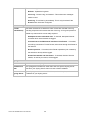
Front-mounted LEDs
Power LED
On (Green) - Power on.
Off - No power.
Flashing (Green) - Device is rebooting.
Status
On (Orange) - Device error.
LAN
For each port, there are 2 LEDs
On (Green) - Corresponding LAN (hub) port is using 100BaseT.
On (Orange) - Corresponding LAN (hub) port is using 10BaseT.
Off - No active connection on the corresponding LAN (hub) port.
Flashing - Data is being transmitted or received via the
corresponding LAN (hub) port.
Wireless
On - Wireless enabled.
Off - No Wireless connections currently exist.
Flashing - Data is being transmitted or received via the Wireless
access point. This includes "network traffic" as well as user data.
ADSL
On - ADSL connection established.
Off - No ADSL connection currently exists.
Flashing - ADSL is synchronizing.
Internet
On (Green) - Internet connection is available.
Off - No Internet connection available.
On (Orange) - Authentication error.
WPS
When pressed, the LED will stay On for 10~15 seconds, then it will
start blinking for 2 minutes. If any client is associated with the router
successfully within 2 minutes, the LED will stay On, otherwise the
LED will be Off.
AirLive WN-300ARM-VPN User’s Manual
10
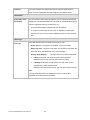
Rear Panel
ADSL port
LAN 1~4
Connect this port to your ADSL line.
Use standard LAN cables (RJ45 connectors) to connect your
PCs to these ports.
Power ON/OFF
Press this button to switch power on/off the device.
Power port
Connect the supplied power adapter here.
Push the WPS button on the device and on your other wireless
WPS Button
device to perform WPS function that easily creates an
encryption-secured wireless connection automatically.
Wireless ON/OFF
Press this button to switch wireless function on or off.
To restore the factory default settings. Press the Wireless and WPS buttons simultaneously
for 8 seconds, and wait the WN-300ARM-VPN to restart using the factory default values.
1.3 Packing List
The following items should be included:
The WN-300ARM-VPN Unit
Installation CD-ROM
Quick Installation Guide
1 x RJ-45 Ethernet cable
1 x RJ-11 cable
1 RJ-11 to RJ45 cable (Annex B only)
AC Adapter
When you open your package, make sure all of the above items are included and not damaged. If you
see that any components are damaged, please notify your dealer immediately.
11
AirLive WN-300ARM-VPN User’s Manual
IIn
nssttaallllaattiio
on
n
C
Ch
haap
ptteerr22..
Requirement
Network cables. Use standard 10/100BaseT network (UTP) cables with RJ45 connectors.
TCP/IP protocol must be installed on all PCs
For Internet Access, an Internet Access account with an ISP, and a DSL connection.
To use the Wireless Access Point, all Wireless devices must be compliant with the IEEE 802.11g,
IEEE 802.11b or IEEE 802.11n Draft specifications.
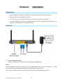
Procedure
1. Choose an Installation Site
Select a suitable place on the network to install the WN-300ARM-VPN.
Notes:
For best Wireless reception and performance, the WN-300ARM-VPN should be positioned in a central
location with minimum obstructions between the WN-300ARM-VPN and the PCs.
Also, if using multiple Access Points, adjacent Access Points should use different Channels.
AirLive WN-300ARM-VPN User’s Manual
12
2. Connect LAN Cables
Use standard LAN cables to connect PCs to the Switching Hub ports on the WN-300ARM-VPN. Both
10BaseT and 100BaseT connections can be used simultaneously.
3. Connect ADSL Cable
Connect the supplied ADSL cable from to the ADSL port on the WN-300ARM-VPN (the RJ11 connector)
to the ADSL terminator provided by your phone company.
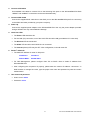
4. Power Up
Connect the supplied power adapter to the WN-300ARM-VPN. Use only the power adapter provided.
Using a different one may cause hardware damage.
5. Check the LEDs
The Power LED should be ON.
For the LAN (PC) connection, one of the LAN LEDs should be ON (provided the PC is also ON).
The Wireless LED should be ON.
The ADSL LED should be ON if ADSL line is connected.
The Internet (Green) LED may be OFF. After configuration, it should come ON.
6. Router’s default IP
The default IP address of router’s LAN port is:
IP Address:
192.168.0.1
Subnet Mask:
255.255.255.0
For Web Management, please configure client PC as DHCP client to obtain IP address from
WN-300ARM-VPN.
After configuring the computer’s IP properly, please enter the router’s IP address “192.168.0.1” in
Web browser to manage the router, type the proper user name and password to pass the router’s
authentication.
7. User name and password
User’s name: admin
Password: airlive
13
AirLive WN-300ARM-VPN User’s Manual
C
Ch
haap
ptteerr33..
S
Seettu
up
p
Overview
This chapter describes the setup procedure for:
Internet Access
LAN configuration
Wireless setup
Assigning a Password to protect the configuration data.
PCs on your local LAN may also require configuration. For details, see Chapter 4 - PC Configuration.
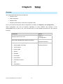
Other configuration may also be required, depending on which features and functions of the
WN-300ARM-VPN you wish to use. Use the table below to locate detailed instructions for the required
functions.
To Do this:
Refer to:
Chapter 4:
Configure PCs on your LAN.
PC Configuration
Check WN-300ARM-VPN operation and Status.
Chapter 5:
Operation and Status
Use any of the following Advanced features:
Chapter 6:
Internet (DMZ, URL Filter)
Advanced Features
Access Control
Dynamic DNS
Options
Schedule
Port Trigger
Port Forward
Port Range Forward
QoS
VPN (IPSec)
AirLive WN-300ARM-VPN User’s Manual
14
Use any of the following Administration Configuration
Chapter 7
settings or features:
Advanced Administration
PC Database
Config File
Logs
E-mail
Diagnostics
Remote Admin
Routing
Upgrade Firmware
Configuration Program
The WN-300ARM-VPN contains an HTTP server. This enables you to connect to it, and configure it using
your Web Browser. Your Browser must support JavaScript.
The configuration program has been tested on the following browsers:
Netscape 7.1 or later.
Mozilla 1.6 or later
Internet Explorer 5.5 or later
Preparation
Before attempting to configure the WN-300ARM-VPN, please ensure that:
Your PC can establish a physical connection to the WN-300ARM-VPN. The PC and the
WN-300ARM-VPN must be directly connected (using the Hub ports on the WN-300ARM-VPN) or on
the same LAN segment.
The WN-300ARM-VPN must be installed and powered ON.
If the WN-300ARM-VPN's default IP Address (192.168.0.1) is already used by another device, the
other device must be turned OFF until the WN-300ARM-VPN is allocated a new IP Address during
configuration.
Using your Web Browser
To establish a connection from your PC to the WN-300ARM-VPN:
1. After installing the WN-300ARM-VPN in your LAN, start your PC. If your PC is already running, restart it.
2. Start your WEB browser.
3. In the Address box, enter "HTTP://" and the IP Address of the WN-300ARM-VPN, as in this example,
which uses the WN-300ARM-VPN's default IP Address:
http://192.168.0.1
15
AirLive WN-300ARM-VPN User’s Manual
4. When prompted for the User name and Password, enter values as follows:
User name
admin
Password
airlive
Notes:
If you can't connect:
If the WN-300ARM-VPN does not respond, check the following:
The WN-300ARM-VPN is properly installed, LAN connection is OK, and it is powered ON. You can test
the connection by using the "Ping" command:
Open the MS-DOS window or command prompt window.
Enter the command:
ping 192.168.0.1
If no response is received, either the connection is not working, or your PC's IP address is not
compatible with the WN-300ARM-VPN's IP Address. (See next item.)
If your PC is using a fixed IP Address, its IP Address must be within the range 192.168.0.2 to
192.168.0.254 to be compatible with the WN-300ARM-VPN's default IP Address of 192.168.0.1. Also, the
Network Mask must be set to 255.255.255.0.
Ensure that your PC and the WN-300ARM-VPN are on the same network segment. (If you don't have a
router, this must be the case.)
Ensure you are using the wired LAN interface. The Wireless interface can only be used if its configuration
matches your PC's wireless settings.
AirLive WN-300ARM-VPN User’s Manual
16
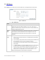
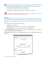
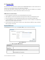
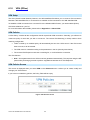
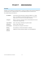
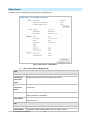
3.1 Setup Wizard
The first time you connect to the WN-300ARM-VPN, you should run the Setup Wizard to configure the ADSL
and Internet Connection.
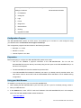
1. Click the Setup Wizard link on the main menu
2. On the first screen, select VC 1 (Router - Primary Internet Connection), then click "Next"
Figure: Setup Wizard Home Page
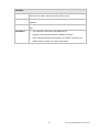
3. Select the method of determining the type of Internet connection, then click “Next”.
Figure: Select desired option
17
AirLive WN-300ARM-VPN User’s Manual
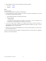
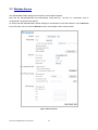
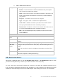
4. On the VC1 screen, shown below, enter the VPI and VCI values provided by your ISP, then click "Next".
Figure: Setup Wizard - VC1
Figure: Setup Wizard - Internet Access
5. On the Internet Access Screen, shown above, select the correct connection type, as used by your ISP.
Click "Next" and complete the configuration for your connection method.
You need the data supplied by your ISP. Your ISP's data will also have the DSL Multiplexing
Method (LLC or VC)
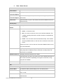
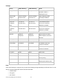
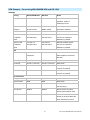
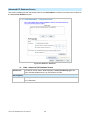
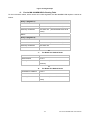
The common connection types are explained in the following table.
AirLive WN-300ARM-VPN User’s Manual
18
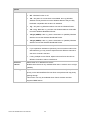
Connection Type
Details
ISP Data required
Dynamic IP Address
Your IP Address is allocated
Often, none.
automatically, when you
Some ISP's may require you to use a
connect to you ISP.
particular Hostname or Domain
name, or MAC (physical) address.
Static (Fixed) IP
Your ISP allocates a
IP Address allocated to you, and
Address
permanent IP Address to you.
related information, such as Network
Usually, the connection is
Mask, Gateway IP address, and DNS
"Always on".
address.
You connect to the ISP only
a) User name and password are
when required. The IP
always required.
address is usually allocated
b) If using a Static (Fixed) IP address,
automatically.
you need the IP address and related
PPPoE, PPPoA
information (Network Mask, Gateway
IP address, and DNS address)
IPoA (IP over ATM)
Normally, the connection is
IP Address allocated to you, and
"Always on".
related information, such as Network
Mask, Gateway IP address, and DNS
address.
6. Step through the Wizard until finished.
7. On the final screen of the Wizard, run the test and check that an Internet connection can be established.
8. If the connection test fails:
Check all connections, and the front panel LEDs.
Check that you have entered all data correctly.
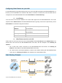
Configuring VCs
The WN-300ARM-VPN supports multiple VCs (Virtual Circuits) on the ADSL connection.
VC1 must be used for general-purpose Internet access. The other VCs are available for special purposes,
such as Video-on-Demand.
You can only use these VCs if supported by your ISP and ADSL service provider. In that case, they will
provide the necessary configuration data.
Notes:
Some ISP's allow multiple PPPoE connections. This allows multiple PCs to connect to the Internet using
PPPoE client software. When using the WN-300ARM-VPN, multiple PPPoE connections are neither
necessary nor supported.
19
AirLive WN-300ARM-VPN User’s Manual
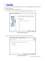
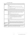
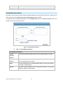
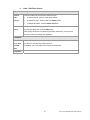
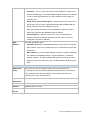
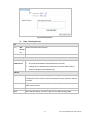
To Configure additional VCs
1. Start the Setup Wizard again.
2. On the first screen, select VC2, and click "Next"
3. Configure the VC setup screen as described below, then click "Next".
Figure: Setup Wizard - VC2
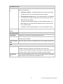
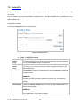
-1-
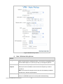
Setup Wizard VC Screen
VC
The VC number is displayed
Enable
To use this VC, you must enable it by checking this checkbox.
VPI
Enter the VPI value provided by your ISP.
VCI
Enter the VPI value provided by your ISP.
Multiplexing
Select the multiplexing value provided by your ISP.
ATM Service
Select the multiplexing value provided by your ISP.
LAN IP
Enter the IP address of the device on your LAN which will receive the data on
Address
this VC.
For Video-on-Demand, this would be the IP address of your SetTop Box.
For VoIP, this would be the IP address of your VoIP TA.
Note that this IP address does not have to be in the same IP address
range as other devices on your local LAN.
4. When finished, click "Next" and complete the Wizard.
5. After completing the Wizard, you can check the Status screen to see the VC has been corrected
established.
AirLive WN-300ARM-VPN User’s Manual
20
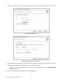
Home Screen
After finishing the Setup Wizard, you will see the Home screen. When you connect in future, you will see this
screen when you connect. An example screen is shown below.
Figure: Home Screen
-2-
Main Menu
The main menu, on the left, contains links to the most-commonly used screen. To see the links to the other
available screens, click "Advanced" or "Administration".
The main menu also contains 2 buttons:
Log Out - When finished, you should click this button to logout.
Restart - When you configure part of feature, the router will need to restart system.
-3-
Navigation & Data Input
Use the menu bar on the left of the screen, and the "Back" button on your Browser, for navigation.
Changing to another screen without clicking "Save" does NOT save any changes you may have made.
You must "Save" before changing screens or your data will be ignored.
Notes:
On each screen, clicking the "Help" button will display help for that screen.
21
AirLive WN-300ARM-VPN User’s Manual
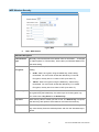
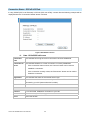
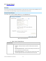
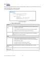
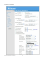
3.2 LAN Screen
Use the LAN link on the main menu to reach the LAN screen. An example screen is shown below.
Figure 1: LAN Screen
-1-
Data - LAN Screen
TCP/IP
IP Address
IP address for the WN-300ARM-VPN, as seen from the local LAN. Use the
default value unless the address is already in use or your LAN is using a
different IP address range. In the latter case, enter an unused IP Address from
within the range used by your LAN.
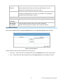
Subnet
The default value 255.255.255.0 is standard for small (class "C") networks. For
Mask
other networks, use the Subnet Mask for the LAN segment to which the
WN-300ARM-VPN is attached (the same value as the PCs on that LAN
segment).
DHCP
If Enabled, the WN-300ARM-VPN will allocate IP Addresses to PCs (DHCP
clients) on your LAN when they start up. The default (and recommended)
Server
value is Enabled.
If you are already using a DHCP Server, this setting must be Disabled, and
the existing DHCP server must be re-configured to treat the
WN-300ARM-VPN as the default Gateway. See the following section for
further details.
The Start IP Address and Finish IP Address fields set the values used by
the DHCP server when allocating IP Addresses to DHCP clients. This
range also determines the number of DHCP clients supported. Enter the
desired value for the Lease Time, which should be between 1 and 7.
See the following section for further details on using DHCP.
AirLive WN-300ARM-VPN User’s Manual
22
DHCP
-2-
What DHCP Does
A DHCP (Dynamic Host Configuration Protocol) Server allocates a valid IP address to a DHCP Client (PC or
device) upon request.
The client request is made when the client device starts up (boots).
The DHCP Server provides the Gateway and DNS addresses to the client, as well as allocating an IP
Address.
The WN-300ARM-VPN can act as a DHCP server.
Windows other non-Server versions of Windows will act as a DHCP client. This is the default
Windows setting for the TCP/IP network protocol. However, Windows uses the term Obtain an IP
Address automatically instead of "DHCP Client".
You must NOT have two (2) or more DHCP Servers on the same LAN segment. (If your LAN does
not have other Routers, this means there must only be one (1) DHCP Server on your LAN.)
-3-
Using the WN-300ARM-VPN's DHCP Server
This is the default setting. The DHCP Server settings are on the LAN screen. On this screen, you can:
Enable or Disable the WN-300ARM-VPN's DHCP Server function.
Set the range of IP Addresses allocated to PCs by the DHCP Server function.
You can assign Fixed IP Addresses to some devices while using DHCP, provided that the Fixed
IP Addresses are NOT within the range used by the DHCP Server.
-4-
Using another DHCP Server
You can only use one (1) DHCP Server per LAN segment. If you wish to use another DHCP Server, rather
than the WN-300ARM-VPN's, the following procedure is required.
Disable the DHCP Server feature in the WN-300ARM-VPN. This setting is on the LAN screen.
Configure the DHCP Server to provide the WN-300ARM-VPN's IP Address as the Default Gateway.
-5-
To Configure your PCs to use DHCP
This is the default setting for TCP/IP for all non-Server versions of Windows.
See Chapter 4 - Client Configuration for the procedure to check these settings.
23
AirLive WN-300ARM-VPN User’s Manual
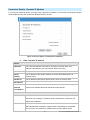
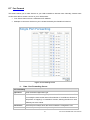
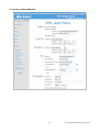
3.3 Wireless Screen
The WN-300ARM-VPN's settings must match the other Wireless stations.
Note that the WN-300ARM-VPN will automatically accept 802.11b, 11g and 11n connections, and no
configuration is required for this feature.
To change the WN-300ARM-VPN's default settings for the Wireless Access Point feature, use the Wireless
link on the main menu to reach the Wireless screen. An example screen is shown below.
Figure: Wireless Screen
AirLive WN-300ARM-VPN User’s Manual
24
-1-
Data - Wireless Screen
Region
Region
Select the correct domain for your location. It is your responsibility to
ensure:
That the WN-300ARM-VPN is only used in domains for which is
licensed.
That you select the correct domain, so that only the legal channels for
that domain can be selected.
Multi SSID
SSID
With Multiple SSIDs, you can have 2 SSIDs on one AP. For example, a
Guest SSID without encryption for visitors to have Internet access only, and
a Admin SSID with encryption for private use to secure your company
resources.
Select the desired SSID from the list to configure.
SSID 1/2
This is also called the "Network Name".
If using an ESS (Extended Service Set, with multiple access points)
this ID is called an ESSID (Extended Service Set Identifier).
To communicate, all Wireless stations should use the same
SSID/ESSID.
Broadcast SSID
If enabled, the WN-300ARM-VPN will broadcast its SSID. This allows PCs
and other wireless stations to detect this Access Point and use the correct
SSID.
If disabled, PC users will have to manually enter the SSID and other details
of the wireless interface before they can connect to this Access Point.
Isolation within
If Enabled, devices that have the same SSID will not be able to see each
SSID
other.
Security Setting
The current Wireless security is displayed. The default value is Disabled.
Configure SSID
Click this button to access the Wireless security sub-screen, and view or
1/2 Button
change the settings. See the following section for details.
25
AirLive WN-300ARM-VPN User’s Manual
Options
802.11 Mode
Select the desired mode:
Off - Wireless function is off.
11b - Only 802.11b connections are available. 802.11g Wireless
Stations will only be able to use the Wireless Router if they are fully
backward-compatible with the 802.11b standard.
11g - Only 802.11g Wireless stations can use the Wireless Router.
11b + 11g - Both 802.11.g and 802.11b Wireless stations will be able
to use the Wireless Broadband Router.
11b/g/n (20MHz) - 802.11.g, 802.11b and 802.11n (20MHz) Wireless
stations can use the Wireless Broadband Router.
11b/g/n (40MHz) - 802.11.g, 802.11b and 802.11n (40MHz) Wireless
stations can use the Wireless Broadband Router.
Channel No.
Select the Channel you wish to use on your Wireless LAN.
If you experience interference (shown by lost connections and/or slow
data transfers) you may need to experiment with different channels to
see which channel is the best.
If using multiple Access Points, adjacent Access Points should use
different Channels to reduce interference.
Extension
Select either UP or DOWN from the list.
Channel
Noted that the feature is only available when 802.11 mode is set to 11b/g/n
(40MHz).
WMM Support
System will auto enable the function. WMM works to classify the packets’
priority, so the WN-300ARM-VPN can allow more packets with top priority
passing through.
This function can only be available when client’s wireless card also
supports WMM feature.
AirLive WN-300ARM-VPN User’s Manual
26
MAC Address Filter
Allow access
Use this feature to determine which Wireless stations can use the Access
by …
Point. The options are:
All Wireless Stations - All wireless stations can use the access point,
provided they have the correct SSID and security settings.
Trusted Wireless stations only - Only wireless stations you designate
as "Trusted" can use the Access Point, even if they have the correct
SSID and security settings.
This feature uses the MAC address to identify Wireless stations. The
MAC address is a low-level network identifier which is unique to each
PC or network device.
To define the trusted wireless stations, use the "Set Stations" button.
Set Stations
Click this button to manage the trusted PC database.
Button
WiFi Protect Setup
Enable WPS
Enable this if you want to use Wireless WPS function.
AP PIN Code
Use the default displayed value or click the Regenerate button to have the
new pin code in the field.
Input Client PIN
Enter the client’s PIN code in the field and click OK to add the client device.
Code
WDS
Enable WDS
This feature allows you to make a completely wireless network by using
multiple access points without connecting them with a wire LAN.
In order to make the WDS working successfully, the access point must use
the same channel, SSID, as well as the wireless encryption method.
MAC Address
Enter the MAC address(es) of the AP(s) into the fields to allow the following
List
access points to be connected to the wireless router.
27
AirLive WN-300ARM-VPN User’s Manual
3.4 Wireless Security
This screen is accessed by clicking the "Configure SSID" button on the Wireless screen. There are 3 options
for Wireless security:
Disabled - no data encryption is used.
WEP - data is encrypted using the WEP standard.
WPA-PSK - data is encrypted using the WPA-PSK standard. This is a later standard than WEP, and
provides much better security than WEP. If all your Wireless stations support WPA-PSK, you should
use WPA-PSK rather than WEP.
WPA2-PSK - This is a further development of WPA-PSK, and offers even greater security, using the
AES (Advanced Encryption Standard) method of encryption.
Mixed WPA-PSK/WAP2-PSK - This method, sometimes called "Mixed Mode", allows clients to use
EITHER WPA-PSK OR WPA2-PSK.
WPA-802.1x - This version of WPA requires a Radius Server on your LAN to provide the client
authentication according to the 802.1x standard. Data transmissions are encrypted using the WPA
standard.
If this option is selected:
This Access Point must have a "client login" on the Radius Server.
Each user must have a "user login" on the Radius Server.
Each user's wireless client must support 802.1x and provide the login data when required.
All data transmission is encrypted using the WPA standard. Keys are automatically generated,
so no key input is required.
AirLive WN-300ARM-VPN User’s Manual
28
WEP Wireless Security
Figure: WEP
-1-
Data - WEP Screen
WEP Data Encryption
Authentication
Normally, this should be left at the default value of "Automatic". If changed
Type
to "Open System" or "Shared Key", ensure that your Wireless Stations use
the same setting.
WEP Data
Select the desired option, and ensure the Wireless Stations use the same
Encryption
setting.
64 Bit - data is encrypted, using the default key, before being
transmitted. You must enter at least the default key. For 64 Bit
Encryption, the key size is 10 chars in HEX (0~9 and A~F).
128 Bit - data is encrypted, using the default key, before being
transmitted. You must enter at least the default key. For 128 Bit
Encryption, the key size is 26 chars in HEX (0~9 and A~F).
Default Key
Select the key you wish to be the default. Transmitted data is ALWAYS
encrypted using the Default Key; the other Keys are for decryption only.
You must enter a Key Value for the Default Key.
Key Value
Enter the key value or values you wish to use. The Default Key is required,
the other keys are optional. Other stations must have the same key.
Passphrase
If desired, you can generate a key from a phrase, instead of entering the
key value directly. Enter the desired phrase, and click the "Generate Keys"
button.
29
AirLive WN-300ARM-VPN User’s Manual
WPA-PSK Wireless Security
Figure: WPA-PSK
-2-
Data - WPA-PSK Screen
WPA-PSK Data Encryption
Enter the PSK (network key). Data is encrypted using a key derived from
PSK
the network key. Other Wireless Stations must use the same network key.
The PSK must be from 8 to 63 characters in length.
The WPA-PSK standard allows different encryption methods to be used.
Encryption
Select the desired option. Wireless Stations must use the same encryption
method.
WPA2-PSK Wireless Security
Figure: WPA2-PSK
-3-
Data - WPA2-PSK Screen
WPA2-PSK Data Encryption
Authentication
This is a further development of WPA-PSK, and offers even greater
security.
PSK
Enter the PSK (network key). Data is encrypted using a key derived from
the network key. Other Wireless Stations must use the same network key.
The PSK must be from 8 to 63 characters in length.
Encryption
The WPA2-PSK standard allows different encryption methods to be used.
Select the desired option. Wireless Stations must use the same encryption.
AirLive WN-300ARM-VPN User’s Manual
30
Mixed WPA-PSK/WAP2-PSK Wireless Security
Figure: Mixed WPA-PSK/WAP2-PSK
-4-
Data - Mixed WPA-PSK/WAP2-PSK Screen
Mixed WPA-PSK/WPA2-PSK Data Encryption
Authentication
This method, sometimes called "Mixed Mode", allows clients to use
EITHER WPA-PSK OR WPA2-PSK.
Enter the PSK (network key). Data is encrypted using a key derived from
PSK
the network key. Other Wireless Stations must use the same network key.
The PSK must be from 8 to 63 characters in length.
The Mixed WPA-PSK/WAP2-PSK standard allows different encryption
Encryption
methods to be used. Select the desired option. Wireless Stations must use
the same encryption method.
WPA-802.1x Wireless Security
Figure: WPA-802.1x
-5-
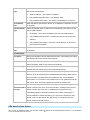
Data - WPA-802.1x Screen
WPA-802.1x Data Encryption
Server Address
Enter the server address here.
Radius Port
Enter the port number used for connections to the Radius Server.
Shared Key
Enter the shared key. Data is encrypted using a key derived from the
network key. Other Wireless Stations must use the same key. The key must
31
AirLive WN-300ARM-VPN User’s Manual
be from 8 to 63 characters in length.
The encryption method is TKIP. Wireless Stations must also use TKIP.
Encryption
Trusted Wireless Stations
This feature can be used to prevent unknown Wireless stations from using the Access Point. This list has no
effect unless the setting Allow access by trusted stations only is enabled.
To change the list of trusted wireless stations, use the Modify List button on the Access Control screen. You
will see a screen like the sample below.
Figure: Trusted Wireless Stations
-6-
Data - Trusted Wireless Stations
Trusted Wireless Stations
Trusted
This lists any Wireless Stations which you have designated as “Trusted”.
Wireless
Stations
Other Wireless
This list any Wireless Stations detected by the Access Point, which you
Stations
have not designated as "Trusted".
Name
The name assigned to the Trusted Wireless Station. Use this when adding
or editing a Trusted Station.
Address
The MAC (physical) address of the Trusted Wireless Station. Use this when
adding or editing a Trusted Station.
AirLive WN-300ARM-VPN User’s Manual
32
Buttons
<<
Add a Trusted Wireless Station to the list (move from the "Other Stations"
list).
Select an entry (or entries) in the "Other Stations" list, and click the " <<
" button.
Enter the Address (MAC or physical address) of the wireless station,
and click the "Add" button.
>>
Delete a Trusted Wireless Station from the list (move to the "Other Stations"
list).
Edit
Select an entry (or entries) in the "Trusted Stations" list.
Click the " >> " button.
Use this to change an existing entry in the "Trusted Stations" list:
1. Select the Station in the Trusted Station list.
2. Click the Edit button. The address will be copied to the "Address" field,
and the Add button will change to Update.
3. Edit the address (MAC or physical address) as required.
4. Click Update to save your changes.
Add (Update)
To add a Trusted Station which is not in the "Other Wireless Stations" list,
enter the required data and click this button.
When editing an existing Wireless Station, this button will change from Add
to Update.
Clear
Clear the Name and Address fields.
33
AirLive WN-300ARM-VPN User’s Manual
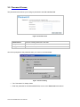
3.5 Password Screen
The password screen allows you to assign a password to the WN-300ARM-VPN.
Figure: Password Screen
Old Password
Enter the existing password in this field.
New password
Enter the new password here.
Verify password
Re-enter the new password here.
You will be prompted for the password when you connect, as shown below.
Figure: Password Dialog
The "User Name" is always admin
Enter the password for the WN-300ARM-VPN, as set on the Password screen above.
AirLive WN-300ARM-VPN User’s Manual
34
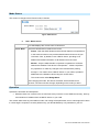
3.6 Mode Screen
Use this screen to change the mode between Router mode and Modem (Bridge) mode.
Figure: Mode Screen
Select the desired option, and click "Save".
Router
Both the ADSL Modem and the Router features are operational. In this mode,
this device can provide shared Internet Access to all your LAN users. Also, by
default, it acts a DHCP Server, providing an IP address and related
information to all Wireless and LAN users.
Modem
Only the ADSL Modem component is operational.
All Router features are disabled. This device is "transparent" - it does not
perform any operations or make any changes to the network traffic
passing through it.
You need to have a DHCP Server on your LAN to provide IP addresses
to the Wireless clients using this Access Point.
All traffic received on either the Wireless or LAN interface will be sent
over the ADSL connection.
Notes:
Generally, you should NOT use modem mode. Only select this mode if you are sure this is what you want.
After changing the mode, this device will restart, which will take a few seconds. The menu will also
change, depending on the mode you are in.
The Wireless Access Point can function in either Router or Modem mode. But generally it is not a good
idea to combine a Modem with an Access Point, because all data received from the wireless stations will
be sent over the modem connection. (Since the modem is transparent, it does not examine the traffic to
determine whether the traffic is for the LAN or the WAN.)
For details on using Modem Mode, see Chapter 8.
35
AirLive WN-300ARM-VPN User’s Manual
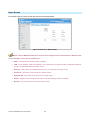
3.7 Binding Screen
The Binding feature is for MultiPVC. If you have enabled multiple PVCs and set the WAN connection methods
individually, you can bind the LAN Ports and WLAN Port to them using this page. While binding one port to the
selected PVC, this port would connect Internet via this PVC. The PVC port should be configured first or the
bound port will not access the Internet.
While in Modem mode, Bridge connection can only be set for all the PVCs. You can click MultiPVC Details in
the Status screen to see all the information.
Note: When you switch to Modem mode from Router (Modem+Router), all the connection methods would be
changed to Bridge. You may need to reconfigure the Bridge IP/Netmask through wizard pages if you want to
access the WEB Server via the relevant port.
Figure: Binding Screen
-1-
Data - Binding Screen
Port 0
This port is always bound to the Primary Internet Connection VC1.
Port 1~3
These ports can be bound to VC2~VC8. If it is not enabled, it would be bound to
VC1 as default.
WLAN
The WLAN Port can be bound to VC2~VC8. If it is not enabled,, it would be
bound to VC1 as default.
VPI/VCI
It displays the current VPI/VCI information of the selected PVC.
Type
It displays the current connection type of the selected PVC.
Group
It shows the group for one port when you have selected a PVC for this port.
AirLive WN-300ARM-VPN User’s Manual
36
C
hapter4.
Chapter4.
onfiguration
P
PC
CC
Configuration
Overview
For each PC, the following may need to be configured:
TCP/IP network settings
Internet Access configuration
Wireless configuration
4.1 Windows Clients
This section describes how to configure Windows clients for Internet access via the WN-300ARM-VPN.
The first step is to check the PC's TCP/IP settings.
The WN-300ARM-VPN uses the TCP/IP network protocol for all functions, so it is essential that the TCP/IP
protocol be installed and configured on each PC.
TCP/IP Settings - Overview
If using the default WN-300ARM-VPN settings, and the default Windows TCP/IP settings, no changes need to
be made.
By default, the WN-300ARM-VPN will act as a DHCP Server, automatically providing a suitable IP
Address (and related information) to each PC when the PC boots.
For all non-Server versions of Windows, the default TCP/IP setting is to act as a DHCP client.
If using a Fixed (specified) IP address, the following changes are required:
The Gateway must be set to the IP address of the WN-300ARM-VPN.
The DNS should be set to the address provided by your ISP.
If your LAN has a Router, the LAN Administrator must re-configure the Router itself. Refer to
Chapter 8 - Advanced Setup for details.
37
AirLive WN-300ARM-VPN User’s Manual
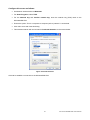
Checking TCP/IP Settings - Windows NT4.0
1. Select Control Panel - Network, and, on the Protocols tab, select the TCP/IP protocol, as shown below.
Figure: Windows NT4.0 - TCP/IP
2. Click the Properties button to see a screen like the one below.
Figure: Windows NT4.0 - IP Address
AirLive WN-300ARM-VPN User’s Manual
38
3. Select the network card for your LAN.
4. Select the appropriate radio button - Obtain an IP address from a DHCP Server or Specify an IP
Address, as explained below.
Obtain an IP address from a DHCP Server
This is the default Windows setting. Using this is recommended. By default, the WN-300ARM-VPN will act
as a DHCP Server.
Restart your PC to ensure it obtains an IP Address from the WN-300ARM-VPN.
Specify an IP Address
If your PC is already configured, check with your network administrator before making the following changes.
1. The Default Gateway must be set to the IP address of the WN-300ARM-VPN. To set this:
Click the Advanced button on the screen above.
On the following screen, click the Add button in the Gateways panel, and enter the
WN-300ARM-VPN's IP address, as shown in below.
If necessary, use the Up button to make the WN-300ARM-VPN the first entry in the Gateways list.
Figure: Windows NT4.0 - Add Gateway
2. The DNS should be set to the address provided by your ISP, as follows:
Click the DNS tab.
On the DNS screen, shown below, click the Add button (under DNS Service Search Order), and
enter the DNS provided by your ISP.
39
AirLive WN-300ARM-VPN User’s Manual
Figure: Windows NT4.0 - DNS
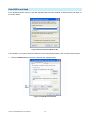
Checking TCP/IP Settings - Windows 2000
1. Select Control Panel - Network and Dial-up Connection.
2. Right - click the Local Area Connection icon and select Properties. You should see a screen like the
following:
Figure: Network Configuration (Win 2000)
AirLive WN-300ARM-VPN User’s Manual
40
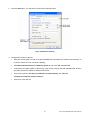
3. Select the TCP/IP protocol for your network card.
4. Click on the Properties button. You should then see a screen like the following.
Figure: TCP/IP Properties (Win 2000)
5. Ensure your TCP/IP settings are correct, as described below.
Using DHCP
To use DHCP, select the radio button Obtain an IP Address automatically. This is the default Windows
setting. Using this is recommended. By default, the WN-300ARM-VPN will act as a DHCP Server.
Restart your PC to ensure it obtains an IP Address from the WN-300ARM-VPN.
Using a fixed IP Address ("Use the following IP Address")
If your PC is already configured, check with your network administrator before making the following changes.
Enter the WN-300ARM-VPN's IP address in the Default gateway field and click OK. (Your LAN
administrator can advise you of the IP Address they assigned to the WN-300ARM-VPN.)
If the DNS Server fields are empty, select Use the following DNS server addresses, and enter the DNS
address or addresses provided by your ISP, then click OK.
41
AirLive WN-300ARM-VPN User’s Manual
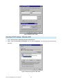
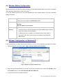
Checking TCP/IP Settings - Windows XP
1. Select Control Panel - Network Connection.
2. Right click the Local Area Connection and choose Properties. You should see a screen like the
following:
Figure: Network Configuration (Windows XP)
3. Select the TCP/IP protocol for your network card.
4. Click on the Properties button. You should then see a screen like the following.
Figure: TCP/IP Properties (Windows XP)
5. Ensure your TCP/IP settings are correct.
AirLive WN-300ARM-VPN User’s Manual
42
Using DHCP
To use DHCP, select the radio button Obtain an IP Address automatically. This is the default Windows
setting. Using this is recommended. By default, the WN-300ARM-VPN will act as a DHCP Server.
Restart your PC to ensure it obtains an IP Address from the WN-300ARM-VPN.
Using a fixed IP Address ("Use the following IP Address")
If your PC is already configured, check with your network administrator before making the following changes.
In the Default gateway field, enter the WN-300ARM-VPN's IP address and click OK. Your LAN
administrator can advise you of the IP Address they assigned to the WN-300ARM-VPN.
If the DNS Server fields are empty, select Use the following DNS server addresses, and enter the DNS
address or addresses provided by your ISP, then click OK.
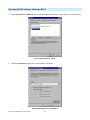
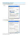
Checking TCP/IP Settings - Windows Vista
1. Select Control Panel - Network Connections.
2. Right click the Local Area Connection Status and choose Properties. Click Continue to the User
Account Control dialog box, then you should see a screen like the following:
Figure: Network Configuration (Windows Vista)
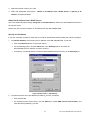
3. Select the TCP/IP protocol for your network card.
4. Click on the Properties button. You should then see a screen like the following.
43
AirLive WN-300ARM-VPN User’s Manual
Figure: TCP/IP Properties (Windows Vista)
5. Ensure your TCP/IP settings are correct.
Using DHCP
To use DHCP, select the radio button Obtain an IP Address automatically. This is the default Windows
setting. To work correctly, you need a DHCP server on your LAN.
Using a fixed IP Address ("Use the following IP Address")
If your PC is already configured for a fixed (specified) IP address, no changes are required.
(The Administrator should configure the Wireless Access Point with a fixed IP address from the same address
range used on the PCs.)
Internet Access
To configure your PCs to use the WN-300ARM-VPN for Internet access:
Ensure that the DSL modem, Cable modem, or other permanent connection is functional.
Use the following procedure to configure your Browser to access the Internet via the LAN, rather than
by a Dial-up connection.
-1-
For Windows 2000
1. Select Start Menu - Settings - Control Panel - Internet Options.
2. Select the Connection tab, and click the Setup button.
AirLive WN-300ARM-VPN User’s Manual
44
3. Select "I want to set up my Internet connection manually, or I want to connect through a local area
network (LAN)" and click Next.
4. Select "I connect through a local area network (LAN)" and click Next.
5. Ensure all of the boxes on the following Local area network Internet Configuration screen are unchecked.
6. Check the "No" option when prompted "Do you want to set up an Internet mail account now?"
7. Click Finish to close the Internet Connection Wizard.
8. Setup is now completed.
-2-
For Windows XP
1. Select Start Menu - Control Panel - Network and Internet Connections.
2. Select Set up or change your Internet Connection.
3. Select the Connection tab, and click the Setup button.
4. Cancel the pop-up "Location Information" screen.
5. Click Next on the "New Connection Wizard" screen.
6. Select "Connect to the Internet" and click Next.
7. Select "Set up my connection manually" and click Next.
8. Check "Connect using a broadband connection that is always on" and click Next.
9. Click Finish to close the New Connection Wizard.
10. Setup is now completed.
-3-
Accessing AOL
To access AOL (America On Line) through the WN-300ARM-VPN, the AOL for Windows software must be
configured to use TCP/IP network access, rather than a dial-up connection. The configuration process is as
follows:
Start the AOL for Windows communication software. Ensure that it is Version 2.5, 3.0 or later. This
procedure will not work with earlier versions.
Click the Setup button.
Select Create Location, and change the location name from "New Locality" to "WN-300ARM-VPN".
Click Edit Location. Select TCP/IP for the Network field. (Leave the Phone Number blank.)
Click Save, then OK.
Before clicking "Sign On", always ensure that you are using the "WN-300ARM-VPN" location.
Configuration is now complete.
45
AirLive WN-300ARM-VPN User’s Manual
4.2 Macintosh Clients
From your Macintosh, you can access the Internet via the WN-300ARM-VPN. The procedure is as follows.
1. Open the TCP/IP Control Panel.
2. Select Ethernet from the Connect via pop-up menu.
3. Select Using DHCP Server from the Configure pop-up menu. The DHCP Client ID field can be left
blank.
4. Close the TCP/IP panel, saving your settings.
Note:
If using manually assigned IP addresses instead of DHCP, the required changes are:
Set the Router Address field to the WN-300ARM-VPN's IP Address.
Ensure your DNS settings are correct.
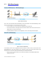
4.3 Linux Clients
To access the Internet via the WN-300ARM-VPN, it is only necessary to set the WN-300ARM-VPN as the
"Gateway".
Ensure you are logged in as "root" before attempting any changes.
Fixed IP Address
By default, most Unix installations use a fixed IP Address. If you wish to continue using a fixed IP Address,
make the following changes to your configuration.
Set your "Default Gateway" to the IP Address of the WN-300ARM-VPN.
Ensure your DNS (Name server) settings are correct.
To act as a DHCP Client (recommended)
The procedure below may vary according to your version of Linux and X -windows shell.
1. Start your X Windows client.
2. Select Control Panel - Network
3. Select the "Interface" entry for your Network card. Normally, this will be called "eth0".
4. Click the Edit button, set the "protocol" to "DHCP", and save this data.
5. To apply your changes:
Use the "Deactivate" and "Activate" buttons, if available.
OR, restart your system.
Other Unix Systems
To access the Internet via the WN-300ARM-VPN:
Ensure the "Gateway" field for your network card is set to the IP Address of the WN-300ARM-VPN.
Ensure your DNS (Name Server) settings are correct.
AirLive WN-300ARM-VPN User’s Manual
46
4.4 Wireless Station Configuration
This section applies to all Wireless stations wishing to use the WN-300ARM-VPN's Access Point, regardless
of the operating system which is used on the client.
To use the Wireless Access Point in the WN-300ARM-VPN, each Wireless Station must have compatible
settings, as follows:
Mode
The mode must be set to Infrastructure (rather than Ad-hoc)
Access points only operate in Infrastructure mode.
SSID (ESSID)
This must match the value used on the WN-300ARM-VPN. The default value is
Wireless.
Note! The SSID is case sensitive.
Wireless
By default, Wireless security on the WN-300ARM-VPN is disabled.
Security
If Wireless security remains disabled on the WN-300ARM-VPN, all stations
must have wireless security disabled.
If Wireless security is enabled on the Wireless Router (either WEP or
WPA-PSK), each station must use the same settings as the Wireless
ADLS Router.
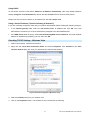
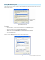
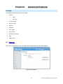
4.5 Wireless Configuration on Windows XP
If using Windows XP to configure the Wireless interface on your PC, the configuration procedure is as follows:
1. Open the Network Connections folder. (Start - Settings - Network Connections)
Figure: Network Connections (Windows XP)
2. Right-click the Wireless Network Connection, check that it is enabled (menu option says Disable, rather
than Enable) and then select View Available Wireless Networks.
3. You will then see a list of wireless networks.
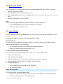
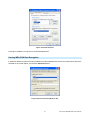
47
AirLive WN-300ARM-VPN User’s Manual
Figure: Wireless Networks (Windows XP)
If the "Broadcast SSID" setting on the WN-300ARM-VPN has been disabled, its SSID will NOT be
listed. See the following section "If the SSID is not listed" for details of dealing with this situation.
4. The next step depends on whether or not Wireless security has been enabled on the WN-300ARM-VPN.
If Wireless Security is Disabled
If Wireless security on the WN-300ARM-VPN is disabled, Windows will warn you that the Wireless network is
not secure.
Figure: Insecure Wireless Network (Windows XP)
To connect:
Check the checkbox Allow me to connect to the selected wireless network, even though it is
not secure.
The Connect button will then be available. Click the Connect button, and wait a few seconds for the
connection to be established.
AirLive WN-300ARM-VPN User’s Manual
48
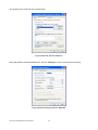
If using WEP Data Encryption
If WEP data encryption has been enabled on the WN-300ARM-VPN, Windows will detect this, and show a
screen like the following.
Figure: WEP (Windows XP)
To connect:
Enter the WEP key, as set on the WN-300ARM-VPN, in the Network Key field.
Re-enter the WEP key into the Confirm Network key field.
Disable the checkbox Enable IEEE 802.1x authentication for this network.
Click the Connect button.
If this fails, click the Advanced button, to see a screen like the following:
49
AirLive WN-300ARM-VPN User’s Manual
Select the SSID for the WN-300ARM-VPN, and click Configure, to see a screen like the following:
Figure: Wireless Network Properties - WEP
Configure this screen as follows:
Set Network Authentication to match the WN-300ARM-VPN. (If the setting on the
WN-300ARM-VPN is "Auto", then either Open or Shared can be used.)
For Data Encryption, select WEP.
For the Network key and Confirm network key, enter the default key value used on the
WN-300ARM-VPN. (Windows will determine if 64bit or 128bit encryption is used.)
The Key index must match the default key index on the WN-300ARM-VPN. The default value is 1.
Ensure the options The key is provided for me automatically and This is a
computer-to-computer (ad hoc) network are unchecked.
Click OK to save and close this dialog.
This wireless network will now be listed in Preferred Networks on the screen below.
AirLive WN-300ARM-VPN User’s Manual
50
Figure: Preferred Networks
Click OK to establish a connection to the WN-300ARM-VPN.
If using WPA-PSK Data Encryption
If WPA-PSK data encryption has been enabled on the WN-300ARM-VPN, it does not matter which network is
selected on the screen below. Just click the Advanced button.
Figure: Wireless Networks (Windows XP)
51
AirLive WN-300ARM-VPN User’s Manual
You will then see a screen like the example below.
Figure: Advanced - Wireless Networks
Select the SSID for the WN-300ARM-VPN, and click Configure, to see a screen like the following:
Figure: Wireless Network Properties- WPA-PSK
AirLive WN-300ARM-VPN User’s Manual
52
Configure this screen as follows:
Set Network Authentication to WPA-PSK.
For Data Encryption, select TKIP.
For the Network key and Confirm network key, enter the network key (PSK) used on the
WN-300ARM-VPN.
Ensure the option “This is a computer-to-computer (ad hoc) network” is unchecked.
Click OK to save and close this dialog.
This wireless network will now be listed in Preferred Networks on the screen below.
Figure: Preferred Networks
Click OK to establish a connection to the WN-300ARM-VPN.
53
AirLive WN-300ARM-VPN User’s Manual
If the SSID is not listed
If the "Broadcast SSID" setting on the WN-300ARM-VPN has been disabled, its SSID will NOT be listed on
the screen below.
Figure: Wireless Networks (Windows XP)
In this situation, you need to obtain the SSID from your network administrator, then to follow this procedure:
1. Click the Advanced button to see a screen like the example below.
Figure: Unlisted Wireless Network
AirLive WN-300ARM-VPN User’s Manual
54
2. Click the Add button. You will see a screen like the example below.
Figure: Add Wireless Network
3. Configure this screen as follows:
Enter the correct SSID, as used on the WN-300ARM-VPN. Remember the SSID is case-sensitive, so
be sure to match the case, not just the spelling.
Set Network Authentication and Data Encryption to match the WN-300ARM-VPN.
If using data encryption (WEP or WPA-PSK), enter the key used on the WN-300ARM-VPN. See the
preceding sections for details of WEP and WPA-PSK.
Uncheck the options “The key is provided for me automatically” and “This is a
computer-to-computer (ad hoc) network”.
Click OK to save and exit.
55
AirLive WN-300ARM-VPN User’s Manual
4. This wireless network will then be listed in Preferred Networks on the screen below.
Figure: Preferred Networks
5. Click OK to establish a connection to the WN-300ARM-VPN.
AirLive WN-300ARM-VPN User’s Manual
56
C
hapter5.
Chapter5.
eration aand
nd S
tatus
O
peration
Status
Op
Operation - Router Mode
Once both the WN-300ARM-VPN and the PCs are configured, operation is automatic.
However, there are some situations where additional Internet configuration may be required. Refer to
Chapter 6 - Advanced Features for further details.
Operation - Router Mode
Use the Status link on the main menu to view this screen.
Figure: Status Screen
57
AirLive WN-300ARM-VPN User’s Manual
-1-
Data - Status Screen
ADSL
Modem Status
This indicates the status of the ADSL modem component.
DownStream
Displays the speed for the DownStream Connection.
Connection Speed
UpStream
If connected, displays the speed for the Up Stream (upload) ADSL
Connection Speed
Connection.
ADSLDetails
Click this button to open a sub-window and view the details of each VC
(Virtual Circuit).
Internet (VC1)
Connection
Displays the current connection method, as set in the Setup Wizard.
Method
Connection Status
This indicates the current status of the Internet Connection
Active - Connection exists
Idle - No current connection, but no error has been detected. This
condition normally arises when an idle connection is automatically
terminated.
Failed - The connection was terminated abnormally. This could be
caused by Modem failure, or the loss of the connection to the ISP's
server.
If there is an error, you can click the "Connection Details" button to find
out more information.
Internet IP Address
This IP Address is allocated by the ISP (Internet Service Provider). If
using a dynamic IP address, and no connection currently exists, this
information is unavailable.
WAN MAC Address
It displays the MAC address for the WAN.
Connection Details
Click this button to open a sub-window and view a detailed description of
the current connection. Depending on the type of connection, a "log"
may also be available.
MultiPVC Details
Click this button to view the details of multi PVC in the sub-screen.
LAN
IP Address
The IP Address of the WN-300ARM-VPN.
Network Mask
The Network Mask (Subnet Mask) for the IP Address above.
DHCP Server
This shows the status of the DHCP Server function. The value will be
"On" or "Off".
MAC Address
This shows the MAC Address for the WN-300ARM-VPN, as seen on the
LAN interface.
AirLive WN-300ARM-VPN User’s Manual
58
Wireless
SSID 1
It displays the name of the SSID 1.
SSID 2
It displays the name of the SSID 2.
Region
The current region, as set on the Wireless screen.
Channel
This shows the Channel currently used, as set on the Wireless screen.
Wireless AP
This indicates whether or not the Wireless Access Point feature is
enabled.
Broadcast Name
This indicates whether or not the SSID is Broadcast. This setting is on
the Wireless screen.
System
Device Name
The current name of the Router. This name is also the "hostname" for
users with "@Home" type connection.
Firmware Version
The version of the current firmware installed.
Buttons
ADSL Details
View the details of each VC (Virtual Circuit).
Connection Details
Click this button to open a sub-window and view a detailed description of
the current connection.
MultiPVC Details
Click this button to view the details of multi PVC in the sub-screen.
Attached Devices
This will open a sub-window, showing all LAN and Wireless devices
currently on the network.
Refresh Screen
Update the data displayed on screen.
Help
The description of Status item.
59
AirLive WN-300ARM-VPN User’s Manual
Connection Status - PPPoE & PPPoA
If using PPPoE (PPP over Ethernet) or PPPoA (PPP over ATM), a screen like the following example will be
displayed when the "Connection Details" button is clicked.
Figure: PPPoE Status Screen
-2-
Data - PPPoE/PPPoA Screen
Connection
This indicates how long the current connection has been established.
Time
Connection to
This indicates whether or not the connection is currently established.
Server
If the connection does not exist, the "Connect" button can be used to
establish a connection.
If the connection currently exists, the "Disconnect" button can be used to
break the connection.
Negotiation
This indicates the status of the PPPoE Server login.
IP Address
The IP Address of this device, as seen by Internet users. This address is
allocated by your ISP (Internet Service Provider).
Network Mask
The Network Mask associated with the IP Address above.
Buttons
Connect
If not connected, establish a connection to your ISP.
Disconnect
If connected to your ISP, hang up the connection.
Close
Close this window.
AirLive WN-300ARM-VPN User’s Manual
60
Connection Details - Dynamic IP Address
If your access method is "Direct" (no login), with a Dynamic IP address, a screen like the following example
will be displayed when the "Connection Details" button is clicked.
Figure: Connection Details - Fixed/Dynamic IP Address
-3-
Data - Dynamic IP address
Internet
IP Address
The current IP Address of this device, as seen by Internet users. This
address is allocated by your ISP (Internet Service Provider).
Network Mask
The Network Mask associated with the IP Address above.
Default
The IP address of the remote Gateway or Router associated with the IP
Gateway
Address above.
DNS Server
The IP address of the Domain Name Server which is currently used.
DHCP Server
The IP address of your ISP's DHCP Server.
Lease
This indicates when the current IP address was obtained, and how long
Obtained
before this IP address allocation (the DCHP lease) expires.
Lease Expires
Buttons
Release
If an IP Address has been allocated to the WN-300ARM-VPN (by the ISP's
DHCP Server), clicking the "Release" button will break the connection and
release the IP Address.
Renew
If the ISP's DHCP Server has NOT allocated an IP Address for the
WN-300ARM-VPN, clicking the "Renew" button will attempt to re-establish
the connection and obtain an IP Address from the ISP's DHCP Server.
61
AirLive WN-300ARM-VPN User’s Manual
Connection Details - Fixed IP Address
If your access method is "Direct" (no login), with a fixed IP address, a screen like the following example will be
displayed when the "Connection Details" button is clicked.
Figure: Connection Details - Fixed/Dynamic IP Address
-4-
Data - Fixed IP address Screen
Internet
IP Address
The IP Address of this device, as seen by Internet users. This address is
allocated by your ISP (Internet Service Provider).
Subnet Mask
The Subnet Mask associated with the IP Address above.
Default
The IP Address of the remote Gateway or Router associated with the IP
Gateway
Address above.
DNS Server
The IP Address of the Domain Name Server which is currently used.
AirLive WN-300ARM-VPN User’s Manual
62
vanced F
eatures
A
dvanced
Features
Ad
C
hapter6.
Chapter6.
Overview
The following advanced features are provided:
Internet:
DMZ
URL filter
Access Control
Dynamic DNS
Options
Schedule
Port Trigger
Port Foward
Port Range Forward
QoS
VPN (IPSec)
6.1 Internet
This screen provides the access to the DMZ, Special Applications and URL Filter features.
Figure: Internet Screen
63
AirLive WN-300ARM-VPN User’s Manual
DMZ
This feature, if enabled, allows the DMZ computer on your LAN to be exposed to all users on the Internet.
This allows almost any application to be used on the "DMZ PC".
The "DMZ PC" will receive all "Unknown" connections and data.
If the DMZ feature is enabled, you must select the PC to be used as the "DMZ PC".
The "DMZ PC" is effectively outside the Firewall, making it more vulnerable to attacks. For this
reason, you should only enable the DMZ feature when required.
URL Filter
If you want to limit access to certain sites on the Internet, you can use this feature. The URL filter will check
each Web site access. If the address, or part of the address, is included in the block site list, access will be
denied.
On the Advanced Internet screen, select the desired setting:
Disable - disable this feature.
Block Always - allow blocking all of the time, independent of the Schedule page.
Block By Schedule - block according to the settings on the Schedule page.
Click the Configure URL Filter button to open the URL Filter screen, allowing you to create or modify the filter
strings which determine which sites will be blocked.
The URL Filter screen is displayed when the Configure URL Filter button on the Advanced Internet screen
is clicked.
Figure: URL Filter Screen
AirLive WN-300ARM-VPN User’s Manual
64
-1-
Data - URL Filter Screen
Current Filter Strings
Current
The list contains the current list of items to block.
Filter
To add to the list, use the "Add" option below.
Strings
To delete an entry, select it and click Delete button.
To delete all entries, click the Delete All button.
Add Filter
To add to the current list, type the word or domain name you want to block into
String
the field provided, then click the Add button.
Filter strings should be as specific as possible. Otherwise, you may block
access to many more sites than intended.
Trusted PC
Allow this
Enable this to allow one computer to have unrestricted access to the Internet.
PC to Visit
For this PC, the URL filter will be ignored.
Blocked
If enabled, you must select the PC to be the trusted PC.
Sties
Trusted PC
Enter the PC to be the Trusted PC.
65
AirLive WN-300ARM-VPN User’s Manual
6.2 Access Control
Overview
The Access Control feature allows administrators to restrict the level of Internet Access available to PCs on
your LAN. With the default settings, everyone has unrestricted Internet access.
Access Control Screen
To view this screen, select the Access Control link on the Advanced menu.
Figure: Access Control Screen
-1-
Data - Access Control Screen
Internet Access
Access Control
Select the desired options for the current group:
Disable - Nothing is blocked. Use this to create the least restrictive
group.
Block all Internet access - All traffic via the WAN port is blocked. Use
this to create the most restrictive group.
Block selected Services - You can select which Services are to block.
Use this to gain fine control over the Internet access for a group.
AirLive WN-300ARM-VPN User’s Manual
66
Blocked
This lists all defined Services. Select the Services you wish to block. To
Services
select multiple services, hold the CTRL key while selecting. (On the
Macintosh, hold the SHIFT key rather than CTRL.)
Schedule
If Internet access is being blocked, you can choose to apply the blocking
only during scheduled times. (If access is not blocked, no Scheduling is
possible, and this setting has no effect.)
Trusted PCs
Click to Enable
If enabled, restrictions set on this screen do not apply to Trusted PCs.
Trusted PC
"Set Trusted
Click this button to add or remove PCs of the Trusted PCs.
PCs" Button
See the following section for details of the Trusted PCs screen.
Trusted PC Screen
This screen is displayed when the Set Trusted PCs button on the Access Control screen is clicked.
Figure: Trusted PC Screen
Use this screen to add or remove PCs from the current group.
The "Del >>" button will remove the selected PC (in the Trusted PCs list) from the current group.
The "<< Add" button will add the selected PC (in the Other PCs list) to the Trusted PCs group.
67
AirLive WN-300ARM-VPN User’s Manual
6.3 Dynamic DNS
This free service is very useful when combined with the Virtual Server feature. It allows Internet users to
connect to your Virtual Servers using a URL, rather than an IP Address.
This also solves the problem of having a dynamic IP address. With a dynamic IP address, your IP address
may change whenever you connect, which makes it difficult to connect to you.
DDNS Services work as follows:
1. You must register for the service at one of the listed DDNS Service providers.
2. After registration, use the Service provider's normal procedure to obtain your desired Domain name.
3. Enter your DDNS data on the WN-300ARM-VPN's DDNS screen, and enable the DDNS feature.
4. The WN-300ARM-VPN will then automatically ensure that your current IP Address is recorded at the
DDNS service provider's Domain Name Server.
5. From the Internet, users will be able to connect to your Virtual Servers (or DMZ PC) using your Domain
name, as shown on this screen.
Dynamic DNS Screen
Select Advanced on the main menu, then Dynamic DNS, to see a screen like the following:
Figure: DDNS Screen
-1-
Data - Dynamic DNS Screen
DDNS Service
Use a Dynamic
Use this to enable or disable the DDNS feature as required.
DNS Service
Service Provider
Select the desired DDNS Service provider.
Web Site
Click this button to open a new window and connect to the Web site of the
selected DDNS service provider.
AirLive WN-300ARM-VPN User’s Manual
68
DDNS Data
Host Name
Enter the domain name allocated to you by the DDNS Service. If you have
more than one name, enter the name you wish to use.
User Name
Enter your Username for the DDNS Service. (TZO.com uses your E-mail
address.)
Password
Enter your current password for the DDNS Service. (TZO.com calls this a
key.)
DDNS Status
This message is returned by the DDNS Server.
Normally, this message should be "Update successful"
If the message indicates some problem, you need to connect to the
DDNS Service provider and correct this problem.
69
AirLive WN-300ARM-VPN User’s Manual
6.4 Option
This screen allows advanced users to enter or change a number of settings. For normal operation, there is no
need to use this screen or change any settings.
An example Options screen is shown below.
Figure: Options Screen
-1-
Data - Options Screen
Internet
Respond to
Ping
If checked, the WN-300ARM-VPN will respond to Ping (ICMP) packets
received from the Internet.
If not checked, Ping (ICMP) packets from the Internet will be ignored.
Disabling this option provides a slight increase in security.
MTU Size
Enter a value between 600 and 1500.
Note: MTU (Maximum Transmission Unit) size should only be changed if
advised to do so by Technical Support.
UPnP
Enable UPnP
UPnP (Universal Plug and Play) allows automatic discovery and
configuration of equipment attached to your LAN. UPnP is supported by
Windows ME, XP, or later.
Advertisement
If Enabled, this device will be visible via UPnP.
If Disabled, this device will not be visible via UPnP.
Enter the desired value, in minutes. The valid range is from 1 to 1440.
Period
Advertisement
Enter the desired value, in hops. The valid range is from 1 to 255.
Time to Live
AirLive WN-300ARM-VPN User’s Manual
70
6.5 Schedule
This Schedule can be used for the Firewall Rules and the URL filter.
Figure: Schedule Screen
-1-
Data - Schedule Screen
Schedule
Day
Each day of the week can be scheduled independently.
Session 1
Two (2) separate sessions or periods can be defined. Session 2 can be left
Session 2
blank if not required.
Start Time
Enter the start using a 24 hr clock.
Finish Time
Enter the finish time using a 24 hr clock.
Local Time
Time Zone
In order to display your local time correctly, you must select your "Time Zone"
from the list.
Adjust for
If your region uses Daylight Savings Time, you must manually check "Adjust
Daylight
for Daylight Savings Time" at the beginning of the adjustment period, and
Savings Time
uncheck it at the end of the Daylight Savings period.
71
AirLive WN-300ARM-VPN User’s Manual
Use this NTP
If you prefer to use a particular NTP server as the primary NTP server, check
Server
the checkbox "Use this NTP Server" and enter the Server's IP address in the
fields provided.
If this setting is not enabled, the default NTP Servers are used.
Current Time
This displays the current time on the WN-300ARM-VPN, at the time the page
is loaded.
AirLive WN-300ARM-VPN User’s Manual
72
6.6 Port Trigger
If you use Internet applications which use non-standard connections or port numbers, you may find that they
do not function correctly because they are blocked by the WN-300ARM-VPN's firewall. In this case, you can
define the application as a "Port Trigger".
The Port Trigger screen can be reached by clicking the Port Trigger on the screen.
You can then define your Port Trigger. You will need detailed information about the application; this is normally
available from the supplier of the application.
Also, note that the terms "Incoming" and "Outgoing" on this screen refer to traffic from the client (PC)
viewpoint
Figure: Port Trigger Screen
-1-
Data - Port Trigger Screen
Port Trigger
Enable
Use this to Enable or Disable this Special Application as required.
Name
Enter a descriptive name to identify this Special Application.
73
AirLive WN-300ARM-VPN User’s Manual
Outgoing
Type - Select the protocol (TCP or UDP) used when you send data to the
remote system or service.
Ports
Start - Enter the beginning of the range of port numbers used by the
application server, for data you send to it. If the application uses a single
port number, enter it in both the "Start" and "Finish" fields.
Finish - Enter the end of the range of port numbers used by the application
server, for data you send to it. If the application uses a single port number,
enter it in both the "Start" and "Finish" fields.
Incoming
Type - Select the protocol (TCP or UDP) used when you receive data from
the special application or service. (Note: Some applications use different
Ports
protocols for outgoing and incoming data).
Start - Enter the beginning of the range of port numbers used by the
application server, for data you receive. If the application uses a single port
number, enter it in both the "Start" and "Finish" fields.
Finish - Enter the end of the range of port numbers used by the application
server, for data you receive.
AirLive WN-300ARM-VPN User’s Manual
74
6.7 Port Forward
This feature allows you to make Servers on your LAN accessible to Internet users. Normally, Internet users
would not be able to access a server on your LAN because:
Your Server does not have a valid external IP Address.
Attempts to connect to devices on your LAN are blocked by the firewall in this device.
Figure: Port Forwarding Screen
-1-
Data - Port Forwarding Screen
Port Forwarding
Application
Enter the desired application type.
External Port
Traffic from the Internet using this port number will be sent to the Server. This
is normally the same as the Internal Port Number. If it is different, this device
will perform a "mapping" or "translation" function, allowing the server to use a
different port to the clients.
Internal Port
Enter the port numbers which the Server software is configured to use.
Protocol
Select the protocol (TCP or UDP) used by the Server.
75
AirLive WN-300ARM-VPN User’s Manual
IP Address
Enter the desired IP address.
Enabled
Use this to Enable or Disable support for this Server, as required.
AirLive WN-300ARM-VPN User’s Manual
76
6.8 Port Range Forward
This feature allows you to make Servers on your LAN accessible to Internet users. Normally, Internet users
would not be able to access a server on your LAN because:
Figure: Port Range Forwarding Screen
-1-
Data - Port Range Forwarding Screen
Port Range Forwarding
Application
Enter the desired application type.
Start
Enter the beginning of the range of port numbers used by the application
server.
End
Enter the end of the range of port numbers used by the application server.
Protocol
Select the protocol (TCP, UDP or Both) used by the Server.
IP Address
Enter the desired IP address.
Enable
Use this to Enable or Disable support for this Server, as required.
77
AirLive WN-300ARM-VPN User’s Manual
6.9 QoS
The QoS (Quality of Service) feature allows you specify priorities for different traffic. Lower priority traffic will
be slowed down to allow greater throughput or less delay for high priority traffic.
An example QoS screen is shown below.
Figure: QoS Screen
-1-
Data - QoS Screen
QoS Setting
QoS Setting
To disable QoS (Quality of Service), keep the default setting, Disable. To
enable QoS (Quality of Service), click Enable and follow these instructions.
Management
There are 2 options:
Type
Rate Control - The QoS will be managed by the size of the bandwidth.
Priority - The QoS will be managed by the priority.
(1-1)
WAN Setting
DownStream
Enter the desired value for the DownStream Connection.
UpStream
Enter the desired value for the UpStream Connection.
Get from WAN
Click this button to get the values for DownStream and UpStream from WAN.
AirLive WN-300ARM-VPN User’s Manual
78
Category
Applications:
Add a New Application (Once selected, please complete the
following setups.)
Ip/Net: Enter the IP addresses.
Rate: Enter the desired rate value.
Priority: Select the desired option (High, Normal, Low)
Direct: Select Upstream or Downstream as required.
Self-Define
Name. Enter a name for your device.
Port Range: Enter the values for the desired port range.
Protocol: Select the desired option.
Ip/Net: Enter the IP addresses of your device.
Rate: Enter the desired rate value.
Priority: Select the option (High, Normal, Low) from the list.
Direct: Select Upstream or Downstream as required.
Summary
Priority
Name
Information
The priority of the application.
The Name of this Application or IP Address.
The general Information of this Application or IP Address.
79
AirLive WN-300ARM-VPN User’s Manual
6.10
VPN (IPSec)
VPN Setup
The VPN (Virtual Private Network) feature in the WN-300ARM-VPN allows you to create a VPN connection
between 2 WN-300ARM-VPN, or a remote PC to establish a VPN connection to the WN-300ARM-VPN.
To establish a VPN connection from a remote PC to the Wireless ADSL Router, you need suitable (IPSec)
VPN client software on your PC.
For more information about VPNs, please refer to Appendix C - About VPNs.
VPN Policies
A "VPN Policy" contains all the configuration data for a particular VPN connection. Generally, you will have to
create one policy for each site you wish to connect to. The remote VPN Gateway (or client) needs to have
matching configuration.
Traffic covered by an enabled policy will automatically be sent via a VPN tunnel. If the VPN tunnel
does not exist, it will be created.
The VPN tunnel is created according to the parameters in the SA (Security Association).
The remote VPN Endpoint must have a matching SA, or it will refuse the connection.
The VPN Policies:
Auto - Some parameters for the VPN tunnel are generated automatically. This requires using the IKE
(Internet Key Exchange) protocol to perform negotiations between the 2 VPN Endpoints.
VPN Policies Screen
This screen is displayed when you select VPN on the Advanced menu. It allows you to create, modify and
manage your VPN Policies.
If you have not created any policies, the Policy Table will be empty.
Figure: VPN Policies Screen
AirLive WN-300ARM-VPN User’s Manual
80
-1Policy Table
Data - VPN Policies Screen
The Policy Table contains the following data
Enable - Use this checkbox to Enable or Disable a Policy as required.
Click "Save" after making any changes.
Name - Each policy is given a unique name to identify it. This name is not
known to the remote VPN endpoint; it is used only to assist managing
your policies.
Endpoint - The address of the remote VPN endpoint.
Type - The Type is "Auto" or "Manual" as explained above.
Local LAN - IP address or subnet on your local LAN. Traffic must be
from (or to) these addresses to be covered by this policy.
Remote LAN - IP address or subnet on the remote LAN. Traffic must be
to (or from) these addresses to be covered by this policy.
ESP - ESP (Encapsulating Security Payload) encryption protocol used
for the VPN data.
Buttons
Save
Save any changes to the "Enable" setting for each policy.
Edit
Edit (modify) the selected policy. (Select a policy by clicking on the radio
button.)
Delete
Delete the selected policy. (Select a policy by clicking on the radio button.)
Add Auto
Change to the input screen for an "Auto" policy. See the following section for
Policy
details.
When the new policy is saved, it will appear in the bottom row of the Policy
Table.
VPN Status
View details of each current VPN Tunnel (connection) in a sub-window. You
also have the option of viewing the VPN Log.
VPN Auto Policies Screen
This screen is displayed when you click the Add Auto Policy button on the VPN Policies screen, or when
you edit an existing Auto Policy. It allows you to define or edit an "Auto" VPN policy.
An "Auto" VPN policy uses the IKE (Internet Key Protocol) to exchange and negotiate parameters for the
IPsec SA (Security Association). Because of this negotiation, it is not necessary for all settings on this VPN
Gateway to match the settings on the remote VPN endpoint. Where settings must match, this is indicated.
81
AirLive WN-300ARM-VPN User’s Manual
Figure: VPN-Auto Policy Screen
-2-
Data - VPN-Auto Policy Screen
General
Policy Name
Enter a unique name to identify this policy. This name is not supplied to the
remote VPN endpoint. It is used only to help you manage the policies.
Remote VPN
Select the desired option (Fixed IP address or Fully Qualified Domain
Endpoint
Name) and enter the address of the remote VPN endpoint you wish to
connect to.
Note: The remote VPN endpoint must have this VPN Gateway's address
entered as its "Remote VPN Endpoint".
NetBIOS Enable
Check this if you wish NETBIOS traffic to be forwarded over the VPN
tunnel. The NETBIOS protocol is used by Microsoft Networking.
AirLive WN-300ARM-VPN User’s Manual
82
Local LAN
Local LAN
This identifies which PCs on your LAN are covered by this policy. For each
selection, data must be provided as follows:
Single address
Enter an IP address in the "IP address" field. Typically, this setting is
used when you wish to make a single Server on your LAN available to
remote users.
Subnet address
Enter an IP address in the "IP address" field, and the desired network
mask in the "Subnet Mask" field.
The remote VPN endpoint must have these IP addresses entered as its
"Remote" addresses.
Remote LAN
Remote LAN
This identifies which PCs on the remote LAN are covered by this policy. For
each selection, data must be provided as follows:
Single address
Enter an IP address in the "IP address" field. This must be an address
on the remote LAN. Typically, this setting is used when you wish to
access a server on the remote LAN.
Subnet address
Enter an IP address in the "IP address" field, and the desired network
mask in the "Subnet Mask" field.
The remote VPN endpoint must have these IP addresses entered as its
"Local" addresses.
IKE
Direction
This setting is used when determining if the IKE policy matches the current
traffic. Select the desired option.
Responder only - Incoming connections are allowed, but outgoing
connections will be blocked.
Initiator and Responder - Both incoming and outgoing connections are
allowed.
Exchange Mode
IPSec has 2 possibilities - "Main Mode" and "Aggressive Mode".
WN-300ARM-VPN only supports "Main Mode". So, user also has to ensure
the remote VPN endpoint is set to use "Main Mode".
Diffie-Hellman
The Diffie-Hellman algorithm is used when exchanging keys. The DH
(DH) Group
Group setting determines the number of bit size used in the exchange. This
value must match the value used on the remote VPN Gateway.
83
AirLive WN-300ARM-VPN User’s Manual
Local Identity
Select the desired option to match the "Remote Identity Type" setting on
Type
the remote VPN endpoint.
WAN IP Address - your Internet IP address.
Fully Qualified Domain Name - your domain name.
Fully Qualified User Name - your name, E-mail address, or other ID.
Local Identity
Enter the data for the selection above. (If "IP Address" is selected, no input
Data
is required.)
Remote Identity
Select the desired option to match the "Local Identity Type" setting on the
Type
remote VPN endpoint.
IP Address - The Internet IP address of the remote VPN endpoint.
Fully Qualified Domain Name - the Domain name of the remote VPN
endpoint.
Fully Qualified User Name - the name, E-mail address, or other ID of
the remote VPN endpoint.
Remote Identity
Enter the data for the selection above. (If "IP Address" is selected, no input
Data
is required.)
SA Parameters
Encryption
Encryption Algorithm used for both IKE and IPSec. This setting must match
the setting used on the remote VPN Gateway.
Authentication
Authentication Algorithm used for both IKE and IPSec. This setting must
match the setting used on the remote VPN Gateway.
Pre-shared Key
The key must be entered both here and on the remote VPN Gateway. This
method does not require using a CA (Certificate Authority).
SA Life Time
This determines the time interval before the SA (Security Association)
expires. (It will automatically be re-established if necessary.) While using a
short time period (or data amount) increases security, it also degrades
performance. It is common to use periods over an hour (3600 seconds) for
the SA Life Time. This setting applies to both IKE and IPSec SAs.
IPSec PFS
If enabled, security is enhanced by ensuring that the key is changed at
(Perfect Forward
regular intervals. Also, even if one key is broken, subsequent keys are no
Secrecy)
easier to break. (Each key has no relationship to the previous key.)
This setting applies to both IKE and IPSec SAs. When configuring the
remote endpoint to match this setting, you may have to specify the "Key
Group" used. For this device, the "Key Group" is the same as the "DH
Group" setting in the IKE section.
VPN Auto Policies Screen
This screen is displayed when you click the VPN Log button on the VPN Policies screen, or on the Status
AirLive WN-300ARM-VPN User’s Manual
84
screen.
This screen allows you to view details of each current VPN Tunnel (connection). If there are no current
connections, the status table will be empty.
Figure: VPN-Status Screen
-3Tunnel Table
Data - VPN Status Screen
This table contains the following data about each current connection.
Policy Name - The name of the policy. When a policy is created, it must
be given a unique name to identify it.
Remote Endpoint - The address of the remote VPN endpoint.
SPI (In) - This is a unique index number to identify the incoming
connection. For "Auto" policies, the SPI is automatically generated. For
"Manual" policies, the SPI must be entered when the policy is configured.
SPI (Out) - This is a unique index number to identify the outgoing
connection. For "Auto" policies, the SPI is automatically generated. For
"Manual" policies, the SPI must be entered when the policy is configured.
Action - This column will contain a button which allows you to break
(terminate) the current the VPN connection.
Buttons
Auto Refresh
Use this to Enable or Disable auto-refresh for this screen. If enabled, the
screen will be updated every few seconds.
The status bar on the bottom on the screen will indicate if auto-refresh is
enabled or disabled.
VPN Log
Click this button to switch to the VPN log screen.
The VPN log shows details of each connection as it is created.
85
AirLive WN-300ARM-VPN User’s Manual
6.11
VPN (IPSec) Example
Common VPN Situations - VPN Pass-through
Figure: VPN Pass-through
Here, a PC on the LAN behind the Router/Gateway is using VPN software, but the Router/Gateway is NOT
acting as a VPN endpoint. It is only allowing the VPN connection.
The PC software can use any VPN protocol supported by the remote VPN.
The remote VPN Server must support client PCs which are behind a NAT router, and so have an IP
address which is not valid on the Internet.
The Router/Gateway requires no VPN configuration, since it is not acting as a VPN endpoint.
Client PC to VPN Gateway
Figure: Client PC to VPN Gateway
In this situation, the PC must run appropriate VPN client software in order to connect, via the Internet, to the
WN-300ARM-VPN or other VPN Gateway. Once connected, the client PC has the same access to LAN
resources as PCs on the local LAN (unless restricted by the network administrator).
IPsec is not the only protocol which can be used in this situation, but the Wireless ADSL Router
supports IPsec ONLY.
AirLive WN-300ARM-VPN User’s Manual
86
Windows 2000 and Windows XP include an IPsec VPN client program. However, configuration of this
client program for use with the WN-300ARM-VPN is very complex and beyond the scope of this
document.
Connecting 2 LANs via VPN
Figure: Connecting 2 VPN Gateways
This allows two (2) LANs to be connected. PCs on each endpoint gain secure access to the remote LAN.
The 2 LANs MUST use different IP address ranges.
The VPN Policies at each end determine when a VPN tunnel will be established, and what systems
on the remote LAN can be accessed once the VPN connection is established.
It is possible to have simultaneous VPN connections to many remote sites.
VPN Example - Connecting 2 WN-300ARM-VPN
In this example, 2 LANs are connected via VPN. Each end has a WN-300ARM-VPN.
Figure: Connecting 2 WN-300ARM-VPN
Note
The LANs MUST use different IP address ranges.
Both endpoints have fixed WAN (Internet) IP addresses.
This example uses an "Auto" policy, using IKE
87
AirLive WN-300ARM-VPN User’s Manual
Settings
Setting
LAN A Gateway
LAN B Gateway
Notes
Policy Name
Example
Example
Name does not affect
operation. Select a
meaningful name.
Remote VPN
Fixed IP Address
Fixed IP Address
Other endpoint's WAN
Endpoint
60.250.158.64
61.229.35.12
(Internet) IP address.
NetBIOS
Enable
Enable
Disable if not required.
Local LAN
192.168.0.0
192.168.1.0
Local Address subnet.
IP address
255.255.255.0
255.255.255.0
Use a more restrictive
definition if possible.
Mask
Remote LAN
192.168.1.0
192.168.0.0
Remote Address subnet.
IP address
255.255.255.0
255.255.255.0
Use a more restrictive
definition if possible.
Mask
IKE
Direction
Initiator &
Initiator &
Does not have to match.
responder
responder
Either endpoint can block 1
direction.
Exchange mode
Main Mode
Main Mode
Must match
DH Group
Group 2 (1024 bit)
Group 2 (1024 bit)
Must match
Local Identity
IP address
IP address
IP address is the most
common ID method
Remote Identity
WAN IP address
WAN IP address
IP address is the most
common ID method
SA Parameters
Encryption
3DES
3DES
Must match.
Authentication
MD5
MD5
Must match
Pre-shared Key
123456789
123456789
Must match;
use any string.
SA Life time
28800
28800
Does not have to match.
Shorter period will be used.
PFS
Disabled
Disabled
Must match
Note:
Some VPN Gateways or programs let you specify the following settings separately for IKE and IPSec. For this
device, the same settings are used for both IKE and IPSec.
Authentication
Encryption
SA Lifetime
AirLive WN-300ARM-VPN User’s Manual
88
Configuration Settings - Gateway A
Gateway A should be configured as shown below.
Figure: Gateway A Configuration
89
AirLive WN-300ARM-VPN User’s Manual
Configuration Settings - Gateway B
Gateway B should be configured as shown below.
Figure: Gateway B Configuration
AirLive WN-300ARM-VPN User’s Manual
90
VPN Example - Connecting WN-300ARM-VPN and RS-1200
Settings
Setting
WN-300ARM-VPN
RS-1200
Notes
Policy Name
wn-300
wn
Name does not affect
operation. Select a
meaningful name.
Remote VPN
Fixed IP Address
PPPoE
Other endpoint's WAN
Endpoint
60.250.158.64
DDNS enable
(Internet) IP address.
NetBIOS
Enable
Enable
Disable if not required.
Local LAN
192.168.0.0
192.168.1.0
Local Address subnet.
IP address
255.255.255.0
255.255.255.0
Use a more restrictive
definition if possible.
Mask
Remote LAN
192.168.1.0
192.168.0.0
Remote Address subnet.
IP address
255.255.255.0
255.255.255.0
Use a more restrictive
definition if possible.
Mask
IKE
Direction
Initiator &
--
Does not have to match.
responder
Either endpoint can block 1
direction.
Exchange mode
Main Mode
Main Mode
Must match
DH Group
Group 2 (1024 bit)
Group 2 (1024 bit)
Must match
Local Identity
IP address
--
IP address is the most
common ID method
Remote Identity
WAN IP address
--
IP address is the most
common ID method
SA Parameters
Encryption
3DES
3DES
Must match.
Authentication
MD5
MD5
Must match
Pre-shared Key
12345678
12345678
Must match;
use any string.
SA Life time
Default
Default
Does not have to match.
Shorter period will be used.
PFS
Enable
Group 2
If WN-300ARM-VPN sets to
enable, it will auto-detect the
other VPN device of PFS.
91
AirLive WN-300ARM-VPN User’s Manual
Configuration: RS-1200
1. Policy Object VPN IPSec Autokey: Define the IPSec setting
2. Policy Object VPN Tunnel: Configure the else VPN setting
AirLive WN-300ARM-VPN User’s Manual
92
3. Policy Outgoing: Enable IPSec VPN setting
4. Policy Incoming: Enable IPSec VPN setting
93
AirLive WN-300ARM-VPN User’s Manual
Configuration: WN-300ARM-VPN
AirLive WN-300ARM-VPN User’s Manual
94
VPN Example - Connecting WN-300ARM-VPN and IP-2000VPN
Settings
Setting
WN-300ARM-VPN
IP-2000VPN
Notes
Policy Name
To_IP2K
To_WN300
Name does not affect
operation. Select a
meaningful name.
Remote VPN
Fixed IP Address
PPPoE
Other endpoint's WAN
Endpoint
60.250.158.64
DDNS enable
(Internet) IP address.
NetBIOS
Enable
Enable
Disable if not required.
Local LAN
192.168.0.0
192.168.1.0
Local Address subnet.
IP address
255.255.255.0
255.255.255.0
Use a more restrictive
definition if possible.
Mask
Remote LAN
192.168.1.0
192.168.0.0
Remote Address subnet.
IP address
255.255.255.0
255.255.255.0
Use a more restrictive
definition if possible.
Mask
IKE
Direction
Initiator &
Initiator &
Does not have to match.
responder
responder
Either endpoint can block 1
direction.
Exchange mode
Main Mode
Main Mode
Must match
DH Group
Group 2 (1024 bit)
Group 2 (1024 bit)
Must match
Local Identity
IP address
IP address
IP address is the most
common ID method
Remote Identity
WAN IP address
WAN IP address
IP address is the most
common ID method
SA Parameters
Encryption
3DES
3DES
Must match.
Authentication
MD5
MD5
Must match
Pre-shared Key
12345678
12345678
Must match;
use any string.
SA Life time
Default
Default
Does not have to match.
Shorter period will be used.
PFS
Enable
Group 2
If WN-300ARM-VPN sets to
enable, it will auto-detect the
other VPN device of PFS.
95
AirLive WN-300ARM-VPN User’s Manual
Configuration: IP-2000VPN
AirLive WN-300ARM-VPN User’s Manual
96
Configuration: WN-300ARM-VPN
97
AirLive WN-300ARM-VPN User’s Manual
C
hapter7.
Chapter7.
ministration
A
dministration
Ad
Overview
Normally, it is not necessary to use these screens, or change any settings. These screens and settings are
provided to deal with non-standard situations, or to provide additional options for advanced users.
The available settings and features are:
PC Database
This is the list of PCs shown when you select the "DMZ PC" or a "Virtual
Server". This database is maintained automatically, but you can add and
delete entries for PCs which use a Fixed (Static) IP Address.
Config File
Backup or restore the configuration file for the WN-300ARM-VPN. This file
contains all the configuration data.
Logs & E-mail
View or clear all logs, set E-Mailing of log files and alerts.
Diagnostics
Perform a Ping or DNS Lookup.
Remote Admin
Allow settings to be changed from the Internet.
Routing
Only required if your LAN has other Routers or Gateways.
Upgrade
Upgrade the Firmware (software) installed in your WN-300ARM-VPN.
Firmware
AirLive WN-300ARM-VPN User’s Manual
98
7.1 PC Database
The PC Database is used whenever you need to select a PC (e.g. for the "DMZ" PC).
It eliminates the need to enter IP addresses.
Also, you do not need to use fixed IP addresses on your LAN.
However, if you do use a fixed IP address on some devices on your LAN, you should enter details of each
such device into the PC database, using the PC Database screen.
PC Database Screen
An example PC Database screen is shown below.
Figure: PC Database
PCs which are "DHCP Clients" are automatically added to the database, and updated as required.
The WN-300ARM-VPN uses the "Hardware Address" to identify each PC, not the name or IP
address. The "Hardware Address" can only change if you change the PC's network card or adapter.
-1Known PCs
Data - PC Database Screen
This lists all current entries. Data displayed is name (IP Address) type. The
"type" indicates whether the PC is connected to the LAN.
Name
If adding a new PC to the list, enter its name here. It is best if this matches the
PC's "hostname".
IP Address
Enter the IP Address of the PC. The PC will be sent a "ping" to determine its
hardware address. If the PC is not available (not connected, or not powered
On) you will not be able to add it.
Buttons
Refresh
Update the data on screen.
Advanced
View the Advanced version of the PC database screen. See below for details.
99
AirLive WN-300ARM-VPN User’s Manual
Advanced PC Database Screen
This screen is displayed if the "Advanced" button on the PC Database is clicked. It provides more control than
the standard PC Database screen.
Figure: PC Database - Advanced
-2Known PCs
Data - Advanced PC Database Screen
This lists all current entries. Data displayed is name (IP Address) type. The
"type" indicates whether the PC is connected to the LAN.
PC Properties
Name
If adding a new PC to the list, enter its name here. It is best if this matches the
PC's "hostname".
AirLive WN-300ARM-VPN User’s Manual
100
IP Address
Select the appropriate option:
Automatic - The PC is set to be a DHCP client (Windows: "Obtain an IP
address automatically"). The WN-300ARM-VPN will allocate an IP address
to this PC when requested to do so. The IP address could change, but
normally won't.
DCHP Client - Reserved IP Address - Select this if the PC is set to be a
DCHP client, and you wish to guarantee that the WN-300ARM-VPN will
always allocate the same IP Address to this PC.
Enter the required IP address. Only the last field is required; the other
fields must match the WN-300ARM-VPN's IP address.
Fixed IP Address - Select this if the PC is using a Fixed (Static) IP
address. Enter the IP address allocated to the PC. (The PC must be
configured to use this IP address.)
MAC
Select the appropriate option
Address
Automatic discovery - WN-300ARM-VPN will contact the PC and find its
MAC address. This is only possible if the PC is connected to the LAN and
powered on.
MAC address is - Enter the MAC address on the PC. The MAC address is
also called the "Hardware Address", "Physical Address", or "Network
Adapter Address". The WN-300ARM-VPN uses this to provide a unique
identifier for each PC. Because of this, the MAC address can NOT be left
blank.
Buttons
Add as New
Add a new PC to the list, using the data in the "PC Properties" box.
Entry
If "Automatic discovery" (for MAC address) is selected, the PC will be sent a
"ping" to determine its hardware address. This will fail unless the PC is
connected to the LAN, and powered on.
Update
Update (modify) the selected PC, using the data in the "Properties" box.
Selected PC
Clear Form
Clear the "Properties" box, ready for entering data for a new PC.
Refresh
Update the data on screen.
Standard
Click this to view the standard "PC Database" screen.
Screen
101
AirLive WN-300ARM-VPN User’s Manual
7.2 Config File
This feature allows you to download the current settings from the WN-300ARM-VPN, and save them to a file
on your PC.
You can restore a previously-downloaded configuration file to the WN-300ARM-VPN, by uploading it to the
WN-300ARM-VPN.
This screen also allows you to set the WN-300ARM-VPN back to its factory default configuration. Any existing
settings will be deleted.
An example Config File screen is shown below.
Figure: Config File Screen
-1-
Data - Config File Screen
Backup
Use this to download a copy of the current configuration, and store the file on
Config
your PC. Click Backup to start the download.
Restore
This allows you to restore a previously-saved configuration file back to the
Config
WN-300ARM-VPN.
Click Browse to select the configuration file, then click Restore to upload the
configuration file.
WARNING!
Uploading a configuration file will destroy (overwrite) ALL of the existing
settings.
Default Config
Clicking the Factory Defaults button will reset the WN-300ARM-VPN to its
factory default settings.
WARNING!
This will delete ALL of the existing settings.
AirLive WN-300ARM-VPN User’s Manual
102
7.3 Logs
The Logs record various types of activity on the WN-300ARM-VPN. This data is useful for troubleshooting, but
enabling all logs will generate a large amount of data and adversely affect performance.
Since only a limited amount of log data can be stored in the WN-300ARM-VPN, log data can also be E-mailed
to your PC. Use the E-mail screen to configure this feature.
Figure: Logs Screen
-1-
Data - Logs Screen
Logs
Current Time
The current time on the WN-300ARM-VPN is displayed.
Log Data
Current log data is displayed in this panel.
103
AirLive WN-300ARM-VPN User’s Manual
Buttons
There are three (3) buttons
Refresh - Update the log data.
Clear Log - Clear the log, and restart it. This makes new messages
easier to read.
Send Log - E-mail the log immediately. This is only functional if the
E-mail screen has been configured.
Include in Log
Include
Use these checkboxes to determine which events are included in the log.
(Checkboxes)
Checking all options will increase the size of the log, so it is good practice to
disable any events which are not really required.
Attempted access to blocked sites - If checked, attempted Internet
accesses which were blocked are logged.
Connections to the Web-based interface of this Router - If checked,
this will log connections TO this Router, rather than through this Router to
the Internet.
Router operation - If checked, other Router operations (not covered by
the selections above) will be logged.
Known DoS attacks and Port Scans - If checked, Denial of Service
attacks, as well as port scans, will be logged.
Syslog
Disable
Data is not sent to a Syslog Server.
Broadcast on
The Syslog data is broadcast, rather than sent to a specific Syslog server.
LAN
Use this if your Syslog Server does not have a fixed IP address.
Send to this
If your Syslog server has a fixed IP address, select this option, and enter the
Syslog Server
IP address of your Syslog server.
AirLive WN-300ARM-VPN User’s Manual
104
7.4 Email
This screen allows you to E-mail Logs and Alerts. A sample screen is shown below.
Figure: E-mail Screen
-1-
Data - E-mail Screen
E-Mail Notification
Turn E-mail
Check this box to enable this feature. If enabled, the E-mail address
Notification on
information (below) must be provided.
Send to this
Enter the E-mail address the Log is to be sent to.
E-mail address
Outgoing (SMTP)
Enter the address or IP address of the SMTP (Simple Mail Transport
Mail Server
Protocol) Server you use for outgoing E-mail.
Mail Sender
Enter the mail address of the sender. The E-mail will also show this
Address
address as the Sender's address.
My SMTP Mail
To stop spanners, many SMTP mail servers require you to log in to send
Server requires
mail. In this case, enable this checkbox, and enter the login information
authentication
(User name and Password) in the fields below.
User Name
If you have enabled "My SMTP Mail Server requires authentication"
above, enter the User Name required to login to your SMTP Server.
105
AirLive WN-300ARM-VPN User’s Manual
Password
If you have enabled "My SMTP Mail Server requires authentication"
above, enter the password required to login to your SMTP Server.
E-mail Alerts
Send E-mail alerts
You can choose to have alerts E-mailed to you, by checking the desired
immediately
checkboxes. The WN-300ARM-VPN can send an immediate alert when it
detects a significant security incident such as
A known hacker attack is directed at your IP address
A computer on the Internet scans your IP address for open ports
Someone on your LAN (Local Area Network) tries to visit a blocked
site.
E-mail Logs
Send Logs
Select the desired option for sending the log by E-mail.
Never (default) - This feature is disabled; Logs are not sent.
When log is full - The time is not fixed. The log will be sent when the
log is full, which will depend on the volume of traffic.
Hourly, Daily, Weekly...
- The log is sent on the interval specified.
If Daily is selected, the log is sent at the time specified.
Select the time of day you wish the E-mail to be sent.
If Weekly is selected, the log is sent once per week, on the
specified day, at the specified time.
Select the day and the time of day you wish the E-mail to be sent.
Note:
If the log is full before the time specified to send it, it will be sent
regardless of the day and time specified.
AirLive WN-300ARM-VPN User’s Manual
106
7.5 Diagnostics
This screen allows you to perform a "Ping" or a "DNS lookup". These activities can be useful in solving
network problems.
An example Network Diagnostics screen is shown below.
Figure: Network Diagnostics Screen
-1-
Data - Network Diagnostics Screen
Ping
IP Address
Enter the IP address you wish to ping. The IP address can be on your LAN, or
on the Internet.
Note that if the address is on the Internet, and no connection currently exists,
you could get a "Timeout" error. In that case, wait a few seconds and try again.
Ping Button
After entering the IP address, click this button to start the "Ping" procedure. The
results will be displayed in the Ping Results pane.
DNS Lookup
Internet
Enter the Domain name or URL for which you want a DNS (Domain Name
Name
Server) lookup.
Note that if the address in on the Internet, and no connection currently exists,
you could get a "Timeout" error. In that case, wait a few seconds and try again.
Lookup
After entering the Domain name/URL, click this button to start the "DNS
Button
Lookup" procedure.
Routing
Display
Click this button to display the internal routing table. This information can be
used by Technical Support and other staff who understand Routing Tables.
107
AirLive WN-300ARM-VPN User’s Manual
7.6 Remote Administration
If enabled, this feature allows you to manage the WN-300ARM-VPN via the Internet.
Figure: Remote Administration Screen
-1-
Data - Remote Administration Screen
Remote Administration
Enable Remote
Check to allow administration/management via the Internet. (To connect,
Management
see below).
If Disabled, this device will ignore Administration connection attempts from
the Internet.
Current IP
This is the current address you will use when accessing this device from
Address
the Internet. To connect, see details and an example below.
Port Number
Enter a port number between 1 and 65535. The default for HTTP (Web)
connections is port 80, but using port 80 will prevent the use of a Web
"Virtual Server" on your LAN. So using a different port number is
recommended. The default value is 8080.
The port number must be specified in your Browser when you connect. See
the following section for details.
Access Permission
Allow Remote
Select the desired option.
Access
Everyone - allow access by everyone on the Internet.
Only This Computer - allow access by only one IP address. Enter the
desired IP address.
IP Address Range - allow access from a range of IP addresses on the
Internet. Enter a beginning and ending IP address to define the allowed
range.
AirLive WN-300ARM-VPN User’s Manual
108
For security, you should restrict access to as few external IP addresses as
practical.
To connect from a remote PC via the Internet
1. Ensure your Internet connection is established, and start your Web Browser.
2. In the "Address" bar, enter "http://" followed by the Internet IP Address of the WN-300ARM-VPN. If the
port number is not 80, the port number is also required. (After the IP Address, enter ":" followed by the
port number.)
e.g.
http://123.123.123.123.8080
This example assumes the WAN IP Address is 123.123.123.123, and the port number is 8080.
3. You will then be prompted for the login name and password for this device.
109
AirLive WN-300ARM-VPN User’s Manual
7.7 Routing
Overview
You can ignore the “Routing” page if your network topology is constructed as following:
If you don't have other Routers or Gateways on your LAN.
If the WN-300ARM-VPN is only acting as a Gateway for the local LAN segment, ignore the "Routing"
page even if your LAN has other Routers.
You can ignore the RIP Routing page if your network topology is constructed as following:
If your LAN has other Gateways and Routers, and you wish to control which LAN segments use each
Gateway, do NOT enable RIP (Routing Information Protocol). Configure the Static Routing table
instead. (You also need to configure the other Routers.)
You can ignore the Static Routing page if your network topology is constructed as following:
If your LAN has a standard Router (e.g. Cisco) on your LAN, and the WN-300ARM-VPN is to act as a
Gateway for all LAN segments, you can enable RIP (Routing Information Protocol).
If using Windows 2000 Data center Server as a software Router, enable RIP on the WN-300ARM-VPN,
and ensure the following Windows 2000 settings are correct:
Open Routing and Remote Access
In the console tree, select Routing and Remote Access, [server name], IP Routing, RIP
In the "Details" pane, right-click the interface you want to configure for RIP version 2, and then click
"Properties".
On the "General" tab, set Outgoing packet protocol to "RIP version 2 broadcast", and Incoming
packet protocol to "RIP version 1 and 2".
Routing Screen
The routing table is accessed by the Routing link on the Administration menu.
-1-
Using this Screen
Generally, you will use either RIP (Routing Information Protocol) OR the Static Routing Table, as explained
above, although is it possible to use both methods simultaneously.
Static Routing Table
If RIP is not used, an entry in the routing table is required for each LAN segment on your Network,
other than the segment to which this device is attached.
The other Routers must also be configured. See Configuring Other Routers on your LAN later in
this chapter for further details and an example.
AirLive WN-300ARM-VPN User’s Manual
110
Figure: Routing Screen
-2-
Data - Routing Screen
RIP
(2-1)
RIP
Select the desired RIP Direction.
Directi
on
RIP Version
Choose the RIP Version for the Server.
Static Routing
Static Routing
This list shows all entries in the Routing Table.
Table Entries
This area shows details of the selected item in the list.
Change any the properties as required, then click the "Edit" button to
save the changes to the selected entry.
Buttons
Add
Add a new entry to the Static Routing table, using the data shown in the
"Properties" area on screen. The entry selected in the list is ignored, and has
no effect.
Edit
Update the current Static Routing Table entry, using the data shown in the
table area on screen.
Delete
Delete the current Static Routing Table entry.
Save
Save the RIP setting. This has no effect on the Static Routing Table.
111
AirLive WN-300ARM-VPN User’s Manual
Configuring Other Routers on your LAN
It is essential that all IP packets for devices are not on the local LAN be passed to the WN-300ARM-VPN, so
that they can be forwarded to the external LAN, WAN, or Internet. To achieve this, the local LAN must be
configured to use the WN-300ARM-VPN as the Default Route or Default Gateway.
-3-
Local Router
The local router is the Router installed on the same LAN segment as the WN-300ARM-VPN. This router
requires that the Default Route is the WN-300ARM-VPN itself. Typically, routers have a special entry for the
Default Route. It should be configured as follows.
Destination IP
Normally 0.0.0.0, but check your router
Address
documentation.
Network Mask
Normally 0.0.0.0, but check your router
documentation.
Gateway IP Address
The IP Address of the WN-300ARM-VPN.
Metric
1
-4-
Other Routers on the Local LAN
Other routers on the local LAN must use the WN-300ARM-VPN's Local Router as the Default Route. The
entries will be the same as the WN-300ARM-VPN's local router, with the exception of the Gateway IP
Address.
For a router with a direct connection to the WN-300ARM-VPN's local Router, the Gateway IP
Address is the address of the WN-300ARM-VPN's local router.
For routers which must forward packets to another router before reaching the WN-300ARM-VPN's
local router, the Gateway IP Address is the address of the intermediate router.
Static Routing - Example
AirLive WN-300ARM-VPN User’s Manual
112
Figure: Routing Example
-5-
For the WN-300ARM-VPN's Routing Table
For the LAN shown above, with 2 routers and 3 LAN segments, the WN-300ARM-VPN requires 2 entries as
follows.
Entry 1 (Segment 1)
Destination IP Address
192.168.1.0
Network Mask
255.255.255.0 (Standard Class C)
Gateway IP Address
192.168.0.100 (WN-300ARM-VPN's local
Router)
Metric
2
Entry 2 (Segment 2)
Destination IP Address
192.168.2.0
Network Mask
255.255.255.0 (Standard Class C)
Gateway IP Address
192.168.0.100
Metric
3
-6-7-
For Router A's Default Route
Destination IP Address
0.0.0.0
Network Mask
0.0.0.0
Gateway IP Address
192.168.0.1 (WN-300ARM-VPN's IP
Address)
-8-9-
For Router B's Default Route
Destination IP Address
0.0.0.0
Network Mask
0.0.0.0
Gateway IP Address
192.168.1.80 (WN-300ARM-VPN's local
router)
113
AirLive WN-300ARM-VPN User’s Manual
7.8 Upgrade Firmware
The firmware (software) in the WN-300ARM-VPN can be upgraded using your Web Browser.
You must first download the upgrade file, then to select Upgrade Firmware on the Administration menu.
You will see a screen like the following.
Figure: Router Upgrade Screen
To perform the Firmware Upgrade:
1. Click the Browse button and navigate to the location of the upgrade file.
2. Select the upgrade file. Its name will appear in the Upgrade File field.
3. Click the Upload button to commence the firmware upgrade.
AirLive WN-300ARM-VPN User’s Manual
114
C
hapter8.
Chapter8.
dem M
ode
M
odem
Mode
Mo
Overview
There are two modes available on the Mode screen.
Router - Both the ADSL Modem and the Router features are operational. In this mode, this device
can provide shared Internet Access to all your LAN users. Also, by default, it acts a DHCP Server,
providing an IP address and related information to all Wireless and LAN users.
Modem - Only the ADSL Modem component is operational. All Router features are disabled. This
device is "transparent" - it does not perform any operations or make any changes to the network
traffic passing through it. You need to have a DHCP Server on your LAN to provide IP addresses to
the Wireless clients using this Access Point.
This Chapter describes operation while in Modem Mode, also called Bridge Mode.
Management Connections
When this device restarts in Modem mode, the IP address does not change, but the DHCP server is disabled.
However, your PC will usually retain the IP address provided by the DHCP Server, so the connection will be
automatically re-established. You then need to ensure that the IP address of this modem is suitable for your
LAN.
You need to have a DHCP Server on your LAN to provide IP addresses to the Wireless clients using
this Access Point.
This Modem/AP must be a valid device on your LAN, to allow management connections. You must
assign a (fixed) IP address which is within the address range used on your LAN, but not within the
address range used by your DHCP server.
When you connect in future, just connect normally, using the IP address you assigned.
1. Start your WEB browser.
2. In the Address box, enter "http://" and the current IP Address of the WN-300ARM-VPN as in this example,
which uses the WN-300ARM-VPN 's default IP Address:
http://192.168.0.1
3. When prompted for the User name and Password, enter admin for the user name, and the current
password, as set on the password screen. (The password is the same regardless of the mode.)
115
AirLive WN-300ARM-VPN User’s Manual
Home Screen
If in Modem mode, the home screen will look like the example below.
Figure: Home Screen - Modem Mode
When it sets to Modem mode, the menu has also changed, many of the options in Router mode
are not available. The screens available are:
Mode - change back to Router mode, if desired.
LAN - set IP address, mask and gateway. This is the same as in Router mode, except that the DHCP
server is not available while in Modem mode.
Wireless - this screen, and related sub-screens, is the same as in Router mode.
Password - this screen is the same as in Router mode.
Upgrade FW - this screen is the same as in Router mode.
Status - displays current settings and status. See the following section for details.
Binding - this screen is the same as in Router mode.
AirLive WN-300ARM-VPN User’s Manual
116
Mode Screen
This screen is change back to Router mode, if desired.
Figure: Mode Screen
-1-
Data - Mode Screen
Device Name
This field displays the current name of this device.
Device Mode
Select the desired device mode for the router:
Router - Both the ADSL Modem and the Router features are operational.
In this mode, this device can provide shared Internet Access to all your
LAN users. Also, by default, it acts a DHCP Server, providing an IP
address and related information to all Wireless and LAN users.
Modem - Only the ADSL Modem component is operational. All Router
features are disabled. This device is "transparent" - it does not perform
any operations or make any changes to the network traffic passing
through it. You need to have a DHCP Server on your LAN to provide IP
addresses to the Wireless clients using this Access Point.
This mode is also called Bridge Mode.
After changing the mode, this device will restart, which will take a few
seconds. The menu will also change, depending on the mode you are in.
Operation
Operation is automatic and transparent.
Wireless clients can connect to the Access Point if they have the correct SSID and security, but they
must obtain an IP address from the DHCP Server on your LAN.
The modem will act like any other ADSL modem. No routing will be performed, and no client login will be done.
If a client login is required, it must be performed by your Router/Gateway or by software on your PC.
117
AirLive WN-300ARM-VPN User’s Manual
Status Screen
In Modem mode, the Status screen looks like the example below.
Figure: Status Screen - Bridge Mode
-2-
Data - Status Screen (Bridge Mode)
ADSL
Modem Status
This indicates the status of the ADSL modem component.
DownStream
Displays the speed for the DownStream Connection.
Connection
Speed
UpStream
If connected, displays the speed for the Up Stream (upload) ADSL
Connection
Connection.
Speed
VC 1~8 Status
For each VC (Virtual Circuit), the current status is displayed. This will be
either "Enabled" or "Disabled".
ADSL Details
Click this button to open a sub-window and view the details of each VC
(Virtual Circuit).
LAN
IP Address
The IP Address of the WN-300ARM-VPN.
Network Mask
The Network Mask (Subnet Mask) for the IP Address above.
AirLive WN-300ARM-VPN User’s Manual
118
MAC Address
This shows the MAC Address for the WN-300ARM-VPN, as seen on the
LAN interface.
Wireless
SSID 1/2
If using an ESS (Extended Service Set, with multiple access points) this ID
is called an ESSID (Extended Service Set Identifier).
Region
The current region, as set on the Wireless screen.
Channel
This shows the Channel currently used, as set on the Wireless screen.
Wireless AP
This indicates whether or not the Wireless Access Point feature is enabled.
Broadcast Name
This indicates whether or not the SSID is Broadcast. This setting is on the
Wireless screen.
System
Device Name
The current name of the Router. This name is also the "hostname" for users
with an "@Home" type connection.
Firmware
The version of the current firmware installed.
Version
Buttons
ADSL Details
View the details of each VC (Virtual Circuit).
Attached
This will open a sub-window, showing all LAN and Wireless devices
Devices
currently on the network.
Refresh Screen
Update the data displayed on screen.
119
AirLive WN-300ARM-VPN User’s Manual
A
Ap
pp
peen
nd
diixx A
A T
Trro
ou
ub
blleessh
ho
oo
ottiin
ng
g
Overview
This chapter covers some common problems that may be encountered while using the WN-300ARM-VPN
and some possible solutions to them. If you follow the suggested steps and the WN-300ARM-VPN still does
not function properly, contact your dealer for further advice.
General Problems
Problem 1:
Can't connect to the WN-300ARM-VPN to configure it.
Solution 1:
Check the following:
The WN-300ARM-VPN is properly installed, LAN connections are OK, and
it is powered ON.
Ensure that your PC and the WN-300ARM-VPN are on the same network
segment. (If you don't have a router, this must be the case.)
If your PC is set to "Obtain an IP Address automatically" (DHCP client),
restart it.
If your PC uses a Fixed (Static) IP address, ensure that it is using an IP
Address within the range 192.168.0.2 to 192.168.0.254 and thus
compatible with the WN-300ARM-VPN's default IP Address of 192.168.0.1.
Also, the Network Mask should be set to 255.255.255.0 to match the
WN-300ARM-VPN.
In Windows, you can check these settings by using Control
Panel-Network to check the Properties for the TCP/IP protocol.
Internet Access
Problem 1:
When I enter a URL or IP address I get a time out error.
Solution 1:
A number of things could be causing this. Try the following troubleshooting
steps.
Check if other PCs work. If they do, ensure that your PCs IP settings are
correct. If using a Fixed (Static) IP Address, check the Network Mask,
Default gateway and DNS as well as the IP Address.
If the PCs are configured correctly, but still not working, check the
WN-300ARM-VPN. Ensure that it is connected and ON. Connect to it and
check its settings. (If you can't connect to it, check the LAN and power
connections.)
Check the WN-300ARM-VPN's status screen to see if it is working
correctly.
AirLive WN-300ARM-VPN User’s Manual
120
Problem 2:
Some applications do not run properly when using the WN-300ARM-VPN.
Solution 2:
The WN-300ARM-VPN processes the data passing through it, so it is not
transparent.
For incoming connections, you must use the Virtual Server or Firewall Rules to
specify the PC which will receive the incoming traffic.
You can also use the DMZ function. This should work with almost every
application, but:
It is a security risk, since the firewall is disabled.
Only one (1) PC can use this feature.
Wireless Access
Problem 1:
My PC can't locate the Wireless Access Point.
Solution 1:
Check the following.
Your PC is set to Infrastructure Mode. (Access Points are always in
Infrastructure Mode)
The SSID on your PC and the Wireless Access Point are the same.
Remember that the SSID is case-sensitive. So, for example "Workgroup"
does NOT match "workgroup".
Both your PC and the WN-300ARM-VPN must have the same setting for
WEP. The default setting for the WN-300ARM-VPN is disabled, so your
wireless station should also have WEP disabled.
If WEP is enabled on the WN-300ARM-VPN, your PC must have WEP
enabled, and the key must match.
If the WN-300ARM-VPN's Wireless screen is set to Allow Trusted PCs
only, then each of your Wireless stations must have been designated as
"Trusted", or the Wireless station will be blocked.
To see if radio interference is causing a problem, see if connection is
possible when close to the WN-300ARM-VPN.
Remember that the connection range can be as little as 100 feet in poor
environments.
Problem 2:
Wireless connection speed is very slow.
Solution 2:
The wireless system will connect at the highest possible speed, depending on
the distance and the environment. To obtain the highest possible connection
speed, you can experiment with the following:
WN-300ARM-VPN location.
Try adjusting the location and orientation of the WN-300ARM-VPN.
Wireless Channel
If interference is the problem, changing to another channel may show a
121
AirLive WN-300ARM-VPN User’s Manual
marked improvement.
Radio Interference
Other devices may be causing interference. You can experiment by
switching other devices Off, and see if this helps. Any "noisy" devices
should be shielded or relocated.
RF Shielding
Your environment may tend to block transmission between the wireless
stations. This will mean high access speed is only possible when close to
the WN-300ARM-VPN.
AirLive WN-300ARM-VPN User’s Manual
122
A
Ap
pp
peen
nd
diixx B
B A
Ab
bo
ou
utt W
Wiirreelleessss L
LA
AN
Nss
Overview
Wireless LANs can work in either of two (2) modes:
Ad-hoc
Infrastructure
Ad-hoc Mode
Ad-hoc mode does not require an Access Point or a wired (Ethernet) LAN. Wireless Stations (e.g.
notebook PCs with wireless cards) communicate directly with each other.
Infrastructure Mode
In Infrastructure Mode, one or more Access Points are used to connect Wireless Stations (e.g. Notebook
PCs with wireless cards) to a wired (Ethernet) LAN. The Wireless Stations can then access all LAN
resources.
Access Points can only function in "Infrastructure" mode, and can communicate only with
Wireless Stations which are set to "Infrastructure" mode.
BSS/ESS
BSS
A group of Wireless Stations and a single Access Point, all using the same ID (SSID), form a Basic Service
Set (BSS).
Using the same SSID is essential. Devices with different SSIDs are unable to communicate with each other.
ESS
A group of Wireless Stations, and multiple Access Points, all using the same ID (ESSID), form an Extended
Service Set (ESS).
Different Access Points within an ESS can use different Channels. In fact, to reduce interference, it is
recommended that adjacent Access Points SHOULD use different channels.
As Wireless Stations are physically moved through the area covered by an ESS, they will automatically
change to the Access Point which has the least interference or best performance. This capability is called
Roaming. (Access Points do not have or require Roaming capabilities.)
Channels
The Wireless Channel sets the radio frequency used for communication.
Access Points use a fixed Channel. You can select the Channel used. This allows you to choose a
Channel which provides the least interference and best performance. In the USA and Canada, 11
123
AirLive WN-300ARM-VPN User’s Manual
channels are available. If using multiple Access Points, it is better if adjacent Access Points use
different Channels to reduce interference.
In "Infrastructure" mode, Wireless Stations normally scan all Channels, looking for an Access Point. If
more than one Access Point can be used, the one with the strongest signal is used. (This can only
happen within an ESS.)
If using "Ad-hoc" mode (no Access Point), all Wireless stations should be set to use the same
Channel. However, most Wireless stations will still scan all Channels to see if there is an existing
"Ad-hoc" group they can join.
WEP
WEP (Wired Equivalent Privacy) is a standard for encrypting data before it is transmitted.
This is desirable because it is impossible to prevent snoopers from receiving any data which is transmitted by
your Wireless Stations. But if the data is encrypted, then it is meaningless unless the receiver can decrypt it.
If WEP is used, the Wireless Stations and the Access Point must have the same settings for each of
the following:
WEP
Off, 64 Bit, 128 Bit
Key
For 64 Bit encryption, the Key value must match.
For 128 Bit encryption, the Key value must match
WEP Authentication
Open System or Shared Key.
WPA-PSK
WPA-PSK is another standard for encrypting data before it is transmitted. This is a later standard than WEP
(Wired Equivalent Privacy), and provides greater security for your data. Data is encrypted using a 256Bit key
which is automatically generated and changed often.
If all your Wireless stations support WPA-PSK, you should use this instead of WEP.
If WPA-PSK is used, the Wireless Stations and the Access Point must have the same settings for each
of the following:
WPA PSK
Enter the same value on every station and the AP. The
(Pre-shared Key)
PSK must be from 8 to 63 characters in length. The
256Bit key used for the actual encryption is derived
from this key.
Encryption
The same encryption method must be used. The most
common encryption method is TKIP. Another
widely-supported method is AES.
WPA2-PSK
This is a later version of WPA (WPA-PSK). The major change is the use of AES (Advanced Encryption System)
for protecting data. AES is very secure, considered to be unbreakable. The PSK (Pre-shared Key) must be
entered on each Wireless station.
AirLive WN-300ARM-VPN User’s Manual
124
If WPA2-PSK is used, the Wireless Stations and the Access Point must have the same settings for
each of the following:
WPA2 PSK
Enter the same value on every station and the AP. The
(Pre-shared Key)
PSK must be from 8 to 63 characters in length. The
256Bit key used for the actual encryption is derived
from this key.
The same encryption method must be used. The most
Encryption
common encryption method is TKIP. Another
widely-supported method is AES.
WPA-802.1x
This version of WPA requires a Radius Server on your LAN to provide the client authentication according to
the 802.1x standard. Data transmissions are encrypted using the WPA standard.
If this option is used:
The Access Point must have a "client login" on the Radius Server.
Each user must have a "user login" on the Radius Server.
Each user's wireless client must support 802.1x and provide the login data when required.
All data transmission is encrypted using the WPA standard. Keys are automatically generated, so no key input
is required.
Wireless LAN Configuration
To allow Wireless Stations to use the Access Point, the Wireless Stations and the Access Point must use the
same settings, as follows:
Mode
On client Wireless Stations, the mode must be set to
"Infrastructure".
(The Access Point is always in "Infrastructure" mode.)
SSID (ESSID)
Wireless Stations should use the same SSID (ESSID) as the
Access Point they wish to connect to. Alternatively, the SSID can
be set to "any" or null (blank) to allow connection to any Access
Point.
Wireless
The Wireless Stations and the Access Point must use the same
Security
settings for Wireless security. (None, WEP, WPA-PSK,
WPA2-PSK, WPA-802.1x).
125
AirLive WN-300ARM-VPN User’s Manual
A
Ap
pp
peen
nd
diixx C
C A
Ab
bo
ou
utt V
VP
PN
Nss
Overview
A VPN (Virtual Private Network) provides a secure connection between 2 points, over an insecure network typically the Internet. This secure connection is called a VPN Tunnel.
There are many standards and protocols for VPNs. The standard implemented in the WN-300ARM-VPN is
IPSec.
IPSec
IPSec is a near-ubiquitous VPN security standard, designed for use with TCP/IP networks. It works at the
packet level, and authenticates and encrypts all packets traveling over the VPN Tunnel. Thus, it does not
matter what applications are used on your PC. Any application can use the VPN like any other network
connection.
IPsec VPNs exchange information through logical connections called SAs (Security Associations). An SA is
simply a definition of the protocols, algorithms and keys used between the two VPN devices (endpoints).
Each IPsec VPN has two SAs - one in each direction. If IKE (Internet Key Exchange) is used to generate and
exchange keys, there are also SA's for the IKE connection as well as the IPsec connection.
There are two security modes possible with IPSec:
Transport Mode - the payload (data) part of the packet is encapsulated through encryption but the IP
header remains in the clear (unchanged).
The Wireless ADSL Router does NOT support Transport Mode.
Tunnel Mode - everything is encapsulated, including the original IP header, and a new IP header is
generated. Only the new header in the clear (i.e. not protected). This system provides enhanced
security.
The WN-300ARM-VPN always uses Tunnel Mode.
IKE
IKE (Internet Key Exchange) is an optional, but widely used, component of IPsec. IKE provides a method of
negotiating and generating the keys and IDs required by IPSec. If using IKE, only a single key is required to
be provided during configuration. Also, IKE supports using Certificates (provided by CAs - Certification
Authorities) to authenticate the identify of the remote user or gateway.
If IKE is NOT used, then all keys and IDs (SPIs) must be entered manually, and Certificates can NOT be used.
This is called a "Manual Key Exchange".
AirLive WN-300ARM-VPN User’s Manual
126
When using IKE, there are 2 phases to creating the VPN tunnel:
Phase I is the negotiation and establishment up of the IKE connection.
Phase II is the negotiation and establishment up of the IPsec connection.
Because the IKE and IPsec connections are separate, they have different SAs (security associations).
Policies
VPN configuration settings are stored in Policies.
Note that different vendors use different terms. Generally, the terms "VPN Policy", "IPSec Policy", and "IPSec
Proposal" have the same meaning. However, some vendors separate IKE Policies (Phase 1 parameters) from
IPSec Policies (Phase 2 parameters).
For the WN-300ARM-VPN; each VPN policy contains both Phase 1 and Phase 2 parameters (if IKE is used).
Each policy defines:
The address of the remote VPN endpoint
The traffic which is allowed to use the VPN connection.
The parameters (settings) for the IPsec SA (Security Association)
If IKE is used, the parameters (settings) for the IKE SA (Security Association)
Generally, you will need at least one (1) VPN Policy for each remote site for which you wish to establish VPN
connections.
It is possible, and sometimes necessary, to have multiple Policies for the same remote site. However, you
should only Enable one (1) policy at a time.
VPN Configuration
The general rule is that each endpoint must have matching Policies, as follows:
VPN Endpoint
Each VPN endpoint must be configured to initiate or accept connections
address
to the remote VPN client or Gateway.
Usually, this requires having a fixed Internet IP address. However, it is
possible for a VPN Gateway to accept incoming connections from a
remote client where the client's IP address is not known in advance.
Local & Remote
This determines which outgoing traffic will cause a VPN connection to be
LAN definition
established, and which incoming traffic will be accepted. Each endpoint
must be configured to pass and accept the desired traffic from the remote
endpoint.
If connecting 2 LANs, this requires that:
Each endpoint must be aware of the IP addresses used on the other
127
AirLive WN-300ARM-VPN User’s Manual
endpoint.
IKE parameters
The 2 LANs MUST use different IP address ranges.
If using IKE (recommended), the IKE parameters must match (except for
the SA lifetime, which can be different).
IPsec parameters
The IPsec parameters at each endpoint must match.
AirLive WN-300ARM-VPN User’s Manual
128
A
Ap
pp
peen
nd
diixx D
D S
Sp
peecciiffiiccaattiio
on
nss
Multi-Function WN-300ARM-VPN
Model
802.11N WN-300ARM-VPN
ADSL Interface
T1.413, G.DMT, G.lite, multi-mode
Dimensions
157mm(W) * 99mm(D) * 30mm(H)
Operating
0 C to 40 C
Temperature
Storage Temperature
-20 C to 70 C
Network Protocol:
TCP/IP
Network Interface:
4 * 10/100BaseT (RJ45) LAN connection
1 * RJ11 for ADSL line
LEDs
15
Power Adapter
12VDC 1A External
Wireless Interface
Standards
IEEE802.11b, IEEE802.11g, 802.11n Draft
Frequency
2.4 to 2.4835GHz (Industrial Scientific Medical Band)
Channels
Maximum 14 Channels, depending on regulatory authorities
Modulation
CCK, DQPSK, DBPSK, BPSK, QPSK, 16-QAM, 64-QAM,
OFDM
Data Rate
Up to 270 Mbps (802.11n Draft)
Security
WEP 64Bit, 128Bit, WPA-PSK, WPA2-PSK, WPA-802.1X, WPS
Button Support, MAC address checking
Output Power
13dBm (typical)
Receiver Sensitivity
-80dBm Min.
129
AirLive WN-300ARM-VPN User’s Manual