1
ATLAS 830 System Manual
1.
Section 2, Engineering Guidelines
EQUIPMENT DIMENSIONS
The ATLAS 830 is 17.5” W, 12.5” D, and 5.5” H and is equipped for table top use or mounted in a 19-inch
rack (mounting brackets included in shipment). All other equipment (option modules) fit inside the unit.
2.
POWER REQUIREMENTS
AC System
The ATLAS 830 has a maximum power consumption of 200 W and a maximum current draw of 3.5 A
regardless of the configuration of option modules installed in the unit.
Without any option modules installed, the AC powered ATLAS 830 will have a power consumption of
50 W and a current draw of 0.64 A maximum at 115 Vrms.
DC System
The ATLAS 830 has a maximum power consumption of 200 W and a maximum current draw of 4.2 A at
-48 VDCregardless of the configuration of option modules installed in the unit.
Without any option modules installed, the DC powered ATLAS 830 will have a power consumption of
45 W at -48 VDC.
3.
REVIEWING THE FRONT PANEL DESIGN
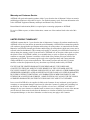
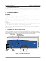
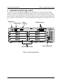
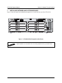
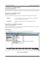
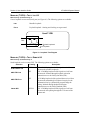
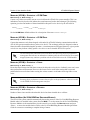
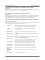
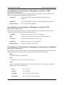
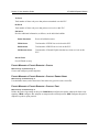
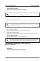
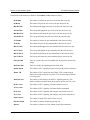
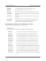
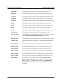
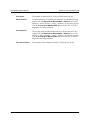
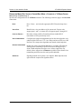
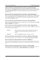
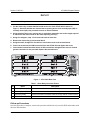
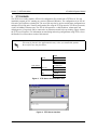
The front panel contains the Alarm Cut-off (ACO) switch, the CRAFT port, and the system and option
module status LEDs. The LEDs provide visual information about the ATLAS 830 and any option module
that may be installed. Figure 1 identifies the ACO switch, the CRAFT port, and the LEDs.
Network LEDs
CRAFT port
(Slot 0, Ports 1&2)
NETWORK
1
2
OK
OK
SYSTEM
TEST
TEST
ERROR
ERROR
ONLINE
ALARM
ALARM
TEST
CRAFT
REMOTE
System
LEDs
1
2
3
4
5
6
7
8
STATUS
ACO
ETHERNET
ATLAS 830
MODULES
POWER
ACO
Switch
Module Status LEDs
Figure 1. ATLAS 830 Front Panel Layout
61200780L1-1A
© 2002 ADTRAN, Inc.
23