1
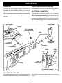
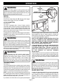
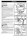
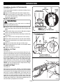
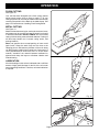
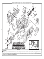
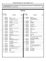
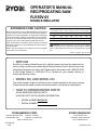
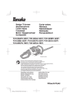
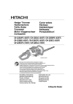
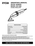
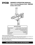
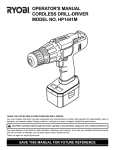
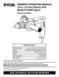
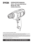
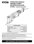
OPERATOR'S MANUAL
RECIPROCATING SAW
RJ150V-01
DOUBLE INSULATED
SPECIFICATIONS:
Length of stroke
Strokes per minute
1 in. (25.4mm)
0-2300 spm
Switch
Adjustable variable speed
Rating
120 volts, 60 Hz, AC
Input
Net weight
6.0 amps
6.5 lbs.
THANK YOU FOR BUYING A RYOBI RECIPROCATING SAW.
Your new saw has been engineered and manufactured to Ryobi's high standard for dependability, ease of operation, and
operator safety. Properly cared for, it will give you years of rugged, trouble-free performance.
CAUTION: Carefully read through this entire operator's manual before using your new saw. Pay close attention
to the Rules for Safe Operation, Warnings, and Cautions. If you use your saw properly and only for what it is intended, you
will enjoy years of safe, reliable service.
Thank you again for buying Ryobi tools.
SAVE THIS MANUAL FOR FUTURE REFERENCE
RULES FOR SAFE OPERATION
THE PURPOSE OF SAFETY SYMBOLS IS TO ATTRACT YOUR ATTENTION TO POSSIBLE DANGERS. THE
SAFETY SYMBOLS, AND THE EXPLANATIONS WITH THEM, DESERVE YOUR CAREFUL ATTENTION AND
UNDERSTANDING. THE SAFETY WARNINGS DO NOT BY THEMSELVES ELIMINATE ANY DANGER. THE
INSTRUCTIONS OR WARNINGS THEY GIVE ARE NOT SUBSTITUTES FOR PROPER ACCIDENT PREVENTION
MEASURES.
SYMBOL
MEANING
SAFETY ALERT SYMBOL:
Indicates warning or caution. May be used in conjunction with other symbols or pictographs.
WARNING: Failure to obey a safety warning can result in serious injury to yourself or to
others. Always follow the safety precautions to reduce the risk of fire, electric shock and
personal injury.
CAUTION: Failure to obey a safety warning may result in property damage or personal injury
to yourself or to others. Always follow the safety precautions to reduce the risk of fire, electric
shock and personal injury.
DOUBLE INSULATION
IMPORTANT
Your Ryobi power tool is double insulated. This means you
are separated from the tool's electrical system by two complete
sets of electrical insulation. This extra layer of insulation is
intended to protect the user from electrical shock due to a
break in the wiring insulation. All exposed metal parts are
isolated from the internal metal motor components with
protecting insulation. Double insulated tools do not need to
be grounded.
Servicing of a tool with double insulation requires extreme
care and knowledge of the system and should be performed
only by a qualified service technician. For service we
suggest you return the tool to your nearest Ryobi
FACTORY SERVICE CENTER or other AUTHORIZED
SERVICE ORGANIZATION for repair. When servicing
use only identical Ryobi replacement parts.
WARNING:
WARNING:
The double insulated system is intended to protect the
user from shock resulting from a break in the tool's
internal wiring. Observe all normal safety precautions
related to avoiding electrical shock.
Do not attempt to operate this tool until you have read
thoroughly and understand completely all instructions,
safety rules, etc. contained in this manual. Failure to
comply can result in accidents involving fire, electric
shock, or serious personal injury. Save operator's manual
and review frequently for continuing safe operation, and
instructing others who may use this tool.
WARNING:
The operation of any reciprocating saw can result in foreign objects being thrown into
your eyes, which can result in severe eye damage. Before beginning power tool
operation, always wear safety goggles or safety glasses with side shields and a full face
shield when needed. We recommend Wide Vision Safety Mask for use over eyeglasses
or standard safety glasses with side shields.
Look for this symbol to point out important safety precautions.
It means attention!!! Your safety is involved.
Page 2
READ ALL INSTRUCTIONS
■ KNOW YOUR POWER TOOL - Read operator's
manual carefully. Learn its applications and limitations as well as the specific potential hazards related to this tool.
■ GUARD AGAINST ELECTRICAL SHOCK BY
PREVENTING BODY CONTACT WITH
GROUNDED SURFACES. For example: Pipes,
radiators, ranges, refrigerator enclosures.
■ KEEP GUARDS IN PLACE and in working order.
■ KEEP WORK AREA CLEAN. Cluttered areas and
benches invite accidents.
■ AVOID DANGEROUS ENVIRONMENT. Don't use
power tool in damp or wet locations or expose to
rain. Keep work area well lit.
■ KEEP CHILDREN AND VISITORS AWAY. All visitors should wear safety glasses and be kept a safe
distance from work area. Do not let visitors contact
tool or extension cord.
■ STORE IDLE TOOLS. When not in use, tools
should be stored in a dry, high or locked-up place out of the reach of children.
■ DON'T FORCE TOOL. It will do the job better and
safer at the rate for which it was designed.
■ USE RIGHT TOOL. Don't force small tool or attachment to do the job of a heavy duty tool. Don't use tool
for purpose not intended - for example - Don't use
a circular saw for cutting tree limbs or logs.
■ WEAR PROPER APPAREL. No loose clothing or
jewelry to get caught in moving parts. Rubber
gloves and nonskid footwear are recommended
when working outdoors. Also, wear protective hair
covering to contain long hair and keep it from being
drawn into air vents.
■ ALWAYS WEAR SAFETY GLASSES. Everyday
eyeglasses have only impact-resistant lenses; they
are NOT safety glasses.
■ PROTECT YOUR LUNGS. Wear a face or dust
mask if operation is dusty.
■ PROTECT YOUR HEARING. Wear hearing protection during extended periods of operation.
■ DON'T ABUSE CORD. Never carry tool by cord or
yank it to disconnect from receptacle. Keep cord
away from heat, oil and sharp edges.
■ SECURE WORK. Use clamps or a vise to hold
work. Both hands are needed to operate the tool.
■ DON'T OVERREACH. Keep proper footing and
balance at all times. Do not use on a ladder or
unstable support.
■ MAINTAIN TOOLS WITH CARE. Keep tools sharp
at all times, and clean for best and safest performance. Follow instructions for lubricating and changing accessories.
■ DISCONNECT TOOLS. When not in use, before
servicing, or when changing attachments, blades,
bits, cutters, etc., all tools should be disconnected
from power supply.
■ REMOVE ADJUSTING KEYS AND WRENCHES.
Form habit of checking to see that keys and adjusting wrenches are removed from tool before turning
it on.
■ AVOID ACCIDENTAL STARTING. Don't carry
plugged-in tools with finger on switch. Be sure
switch is off when plugging in.
■ MAKE SURE YOUR EXTENSION CORD IS IN
GOOD CONDITION. When using an extension
cord, be sure to use one heavy enough to carry the
current your product will draw. An undersized cord
will cause a drop in line voltage resulting in loss of
power and overheating. A wire gage size (A.W.G.)
of at least 12 is recommended for an extension cord
100 feet or less in length. A cord exceeding 100 feet
is not recommended. If in doubt, use the next
heavier gage. The smaller the gage number, the
heavier the cord.
■ OUTDOOR USE EXTENSION CORDS. When tool
is used outdoors, use only extension cords intended for use outdoors and so marked.
■ KEEP BLADES CLEAN AND SHARP. Sharp
blades minimize stalling and kickback. Also, keep
blades properly tightened at all times.
■ KEEP HANDS AWAY FROM CUTTING AREA.
Keep hands away from blades. Do not reach underneath work while blade is cutting. Do not attempt to
remove material while blade is cutting.
■ NEVER USE IN AN EXPLOSIVE ATMOSPHERE.
Normal sparking of the motor could ignite fumes.
■ INSPECT TOOL CORDS PERIODICALLY and if
damaged, have repaired by an authorized service
center. Stay constantly aware of cord location.
■ INSPECT EXTENSION CORDS PERIODICALLY
and replace if damaged.
■ KEEP HANDLES DRY, CLEAN, AND FREE FROM
OIL AND GREASE. Always use a clean cloth when
cleaning. Never use brake fluids, gasoline, petroleum-based products or any strong solvents to
clean your tool.
Page 3
RULES FOR SAFE OPERATION (Continued)
■ STAY ALERT. Watch what you are doing and use
common sense. Do not operate tool when you are
tired. Do not rush.
■ CHECK DAMAGED PARTS. Before further use of
the tool, a guard or other part that is damaged
should be carefully checked to determine that it will
operate properly and perform its intended function.
Check for alignment of moving parts, binding of
moving parts, breakage of parts, mounting, and any
other conditions that may affect its operation. A
guard or other part that is damaged should be
properly repaired or replaced by an authorized
service center unless indicated elsewhere in this
instruction manual.
■ DO NOT USE TOOL IF SWITCH DOES NOT
TURN IT ON AND OFF. Have switches replaced by
an authorized service center.
■ CUTTING INTO ELECTRICAL WIRING IN WALLS
CAN CAUSE BLADE AND METAL PARTS TO
BECOME ELECTRICALLY LIVE. Grasp only the
handle(s) provided on the tool and be sure that
hidden electrical wiring, water pipes, or any mechanical hazards are not in blade path.
■ Inspect for and remove all nails from timber before
cutting.
■ DRUGS, ALCOHOL, MEDICATION. Do not operate tool while under the influence of drugs, alcohol,
or any medication.
■ WHEN SERVICING USE ONLY IDENTICAL
RYOBI REPLACEMENT PARTS.
■ POLARIZED PLUGS. To reduce the risk of electric
shock, this tool has a polarized plug (one blade is
wider than the other). This plug will fit in a polarized
outlet only one way. If the plug does not fit fully in the
outlet, reverse the plug. If it still does not fit, contact
a qualified electrician to install the proper outlet. Do
not change the plug in any way.
■ WARNING: TO AVOID POSSIBLE SERIOUS INJURY, KEEP HANDS AND FINGERS FROM BETWEEN THE MOTOR HOUSING AND SAW
BLADE CLAMP.
■ SAVE THESE INSTRUCTIONS. Refer to them
frequently and use them to instruct others who may
use this tool. If you loan someone this tool, loan
them these instructions also.
EXTENSION CORDS
The use of any extension cord will cause some loss of power.
To keep the loss to a minimum and to prevent tool overheating,
use an extension cord that is heavy enough to carry the
current the tool will draw.
A wire gage size (A.W.G.) of at least 14 is recommended for
an extension cord 50 feet or less in length. A wire gage size
(A.W.G.) of at least 12 is recommended for an extension cord
50 - 100 feet in length. When working outdoors, use an
extension cord that is suitable for outdoor use. The cord's
jacket will be marked WA.
CAUTION:
Keep extension cords away from the cutting area and
position the cord so that it will not get caught on lumber,
tools, etc. during cutting operation.
WARNING:
Check extension cords before each use. If damaged
replace immediately. Never use tool with a damaged cord
since touching the damaged area could cause electrical
shock resulting in serious injury.
SAVE THESE INSTRUCTIONS
WARNING:
WARNING:
If any parts are missing, do not operate your saw until the
missing parts are replaced. Failure to do so could result
in possible serious personal injury.
Do not allow familiarity with your saw to make you
careless. Remember that a careless fraction of a second
is sufficient to inflict severe injury.
Page 4
OPERATION
UNPACKING
KNOW YOUR RECIPROCATING SAW
Your saw has been shipped completely assembled and
ready for use. Inspect it carefully to make sure no breakage
or damage has occurred during shipping. If any parts are
damaged or missing, contact your nearest Ryobi dealer to
obtain replacement parts before attempting to operate saw.
An operator's manual and warranty registration are also
included.
Before attempting to use your saw, familiarize yourself with all
operating features and safety requirements. See Figure 1.
ELECTRICAL CONNECTION
Your saw has a precision built electric motor. It should be
connected to a power supply that is 120 volts, 60 Hz, AC
only (normal household current). Do not operate this tool
on direct current (DC). A substantial voltage drop will cause
a loss of power and the motor will over heat. If your tool does
not operate when plugged into an outlet, double-check the
power supply.
VARIABLE SPEED
CONTROL SELECTOR
TO ROTATE BASE
ASSEMBLY DOWN
LOCK-ON
BUTTON
FLAT HEAD SCREW
(FOR FLUSH CUTTING)
BASE
ASSEMBLY
TO ROTATE BASE
ASSEMBLY UP
ALLEN
WRENCH HOLDER
BLADE
ALLEN WRENCH
BLADE
CLAMP
PIN
BLADE
CLAMP
SCREW
BLADE
CLAMP HOLE
TRIGGER
SET SCREW
(SECURES BASE ASSEMBLY)
Fig. 1
ALLEN WRENCH HOLDER
A convenient feature on your saw is an allen wrench holder.
It is located on the bottom portion of your saw's handle. It is
convenient for storing allen wrench when not in use. See
Figure 1.
Page 5
OPERATION
WARNING:
TO
DECREASE
SPEED
Always wear safety goggles or safety glasses with side
shields when operating your reciprocating saw. Failure to
do so could result in foreign objects being thrown into your
eyes resulting in possible serious injury.
VARIABLE SPEED
CONTROL SELECTOR
TO
INCREASE
SPEED
SWITCH
See Figure 2.
To turn your reciprocating saw ON, depress switch trigger.
Release switch trigger to turn your saw OFF.
LOCK-ON
BUTTON
LOCK-ON BUTTON
See Figure 2.
Your saw is equipped with a "lock-on" feature, which is
convenient when continuous cutting for extended periods of
time is required. To lock-on, depress the switch trigger, push
in and hold the "lock-on" button located on the side of the
handle, then release switch trigger. Release "lock-on" button
and your saw will continue running.
To release the lock, depress the switch trigger and release it.
DO NOT lock the trigger on heavy jobs where your saw may
have to be stopped quickly.
WARNING:
When using your saw with the switch lock-on, keep your
finger near the trigger and be prepared to disengage the
"lock-on" feature at all times. Failure to do so could result
in loss of control leading to possible serious injury.
If you have the "lock-on" feature engaged during use and your
saw becomes disconnected from power supply, disengage
the "lock-on" feature immediately.
WARNING:
Before connecting your saw to power supply source,
always check to be sure it is not in "Lock-on" position
(depress and release switch trigger). Failure to do so
could result in accidental starting of saw resulting in
possible serious injury. Also, do not lock the trigger on
jobs where your saw may need to be stopped suddenly.
VARIABLE SPEED
See Figure 2.
Your reciprocating saw has a variable speed control selector
designed to allow operator control and adjustment of speed
and power limits. The speed and power of your saw can be
increased or decreased by rotating the variable speed control
selector in the direction of the arrows shown in figure 2.
NOTE: Hold your saw in normal operating position and turn
the variable speed control selector clockwise to increase the
speed and power of your saw. Turn counterclockwise to
decrease the speed and power of your saw.
If you desire to lock the switch on at a given speed, depress
Fig. 2
the switch trigger, push in and hold the "lock-on" button, then
while holding the "lock-on" button pushed in release the
switch trigger. Next, adjust the variable speed control selector until the desired speed is reached.
NOTE: IF THE VARIABLE SPEED CONTROL SELECTOR
IS FULLY TURNED IN THE COUNTERCLOCKWISE
DIRECTION (ZERO SETTING) YOUR SAW MAY NOT
RUN. ADJUST THE VARIABLE SPEED CONTROL
SELECTOR TO MAKE SAW OPERATE.
IF YOU DESIRE NOT TO USE THE VARIABLE SPEED
CONTROL SELECTOR, TURN IT IN THE FULL
CLOCKWISE DIRECTION. THIS WILL ALLOW THE
SPEED OF YOUR SAW TO BE FULLY CONTROLLED
BY THE AMOUNT OF SWITCH TRIGGER
DEPRESSION.
Avoid running your saw at low speeds for extended periods
of time. Running at low speeds under constant usage may
cause the motor of your saw to become overheated. If this
occurs, cool your saw by running it without a load and at full
speed.
WARNING:
Your saw should never be connected to power supply
when you are assembling parts, making adjustments,
installing or removing blades, when cleaning, or when not
in use. Disconnecting your saw will prevent accidental
starting that could cause serious injury.
BLADE SELECTION
To obtain the best performance from your saw it is important
to select a specific blade for the particular application and
type of material you wish to cut. By doing this you will get a
smoother faster cut and prolong blade life. Replacement
blades for this saw are available from your nearest Ryobi
dealer.
Page 6
OPERATION
TO INSTALL BLADES
PIN
See Figure 3.
■ UNPLUG YOUR SAW.
SAW BAR
BLADE
WARNING:
Failure to unplug your saw could result in accidental
starting causing serious injury.
■ Remove the 5/32 in. allen wrench provided with this saw
from allen wrench holder. NOTE: Allen wrench holder is
located in bottom portion of saw handle. See Figure 1.
■ Loosen the blade clamp screw enough to permit the saw
blade to be inserted between blade clamp and saw bar.
■ Align the hole in the shank of the blade and blade clamp
with the pin in the saw bar, then seat both on the pin in the
saw bar.
■ Tighten blade clamp screw securely. Do not overtighten
screw or use an aid with allen wrench.
■ Remove allen wrench and store it in allen wrench holder.
NOTE: There may be times when the blade clamp sticks to
the saw bar and will not loosen enough to allow blades to be
installed or removed. If this happens, loosen the blade clamp
screw with the allen wrench, then tap lightly on the end of the
allen wrench with a mallet. See Figure 4.
BLADE
CLAMP
BLADE
CLAMP HOLE
ALLEN
WRENCH
BLADE
CLAMP SCREW
PIN
Fig. 3
ALLEN
WRENCH
SAW BAR
MALLET
BASE ASSEMBLY
See Figure 5.
The base assembly of your reciprocating saw pivots up and
down approximately 15° in both directions. It also is adjustable,
allowing the use of the blade teeth at different positions on the
blade.
Three cutting positions are available when making cuts using
regular blades. Three cutting positions are available when
making cuts using flush cutting blades.
BLADE
CLAMP SCREW
BLADE CLAMP
TO CHANGE POSITIONS OF THE BASE ASSEMBLY:
Fig. 4
■ UNPLUG YOUR SAW.
WARNING:
BASE ASSEMBLY
Failure to unplug your saw could result in accidental
starting causing serious injury.
■ Loosen the set screw in the gear frame with the 5/32 in.
allen wrench mentioned above.
■ Reposition base assembly and align in the desired notch.
NOTE: When changing from cutting with regular blades to
cutting with flush cutting blades, base assembly must be
turned clockwise 90°. Turn counterclockwise 90° when
changing from cutting with flush cutting blades to cutting
with regular blades.
■ Retighten set screw securely. Do not overtighten screw or
use an aid with allen wrench.
■ Remove allen wrench and store it in allen wrench holder.
SET SCREW
NOTCHES FOR
REGULAR CUTS
ALLEN
WRENCH
NOTCH
Page 7
GEAR FRAME
Fig. 5
OPERATION
TO INSTALL FLUSH CUTTING BLADES
See Figures 6 and 7.
Flush cutting blades should be used when making close or
flush cuts to walls.
FLAT
HEAD SCREW
BLADE CLAMP IN
FULL REAR POSITION
PIN
BLADE
CLAMP
■ Plug your reciprocating saw into power supply source.
■ Depress and release the switch trigger of your saw in
quick, short starts and stops until blade clamp is in its full
rear position. See Figure 6.
■ UNPLUG YOUR SAW.
WARNING:
Failure to unplug your saw could result in accidental
starting causing serious injury.
■ Using the 5/32 in. allen wrench provided with your saw,
loosen the blade clamp screw and remove regular saw
blade.
■ Tighten blade clamp screw securely. Do not overtighten
screw or use an aid with allen wrench.
■ Loosen set screw and turn base assembly clockwise 90°.
See Figure 7.
■ Align in desired notch, then tighten set screw securely.
■ Remove allen wrench and store it in allen wrench holder.
■ Insert flush cutting blade on top of blade clamp as shown
in figure 6.
■ Align hole in blade shank with pin on blade clamp.
■ Using the flat head screw provided, secure blade to blade
clamp. See Figure 6.
■ Tighten flat head screw securely.
FLUSH
CUTTING BLADE
Fig. 6
BASE ASSEMBLY IN FLUSH
CUTTING POSITION
FLUSH
CUTTING NOTCHES
SET
SCREW
GENERAL CUTTING
See Figure 8.
Hold your saw firmly in front of and clearly away from you.
Make sure saw blade is clear of any foreign material and that
power cord and extension cord are out of the blade path. Be
sure material to be cut is held firmly. Small work pieces should
be securely clamped in a vise or with clamps to the work
bench or table. Mark the line of cut clearly. Depress the trigger
switch starting the cutting action, set the base assembly
against the work, then move the blade into the work. DO NOT
FORCE. Use only enough pressure to keep the saw cutting.
Let the blade and saw do the work.
BASE ASSEMBLY IN
REGULAR CUTTING POSITION
Fig. 7
PLUNGE CUTTING
See Figure 9.
Mark the line of cut clearly. Choose a convenient starting
point inside the area to be cut out and place the tip of the blade
over that point. Rest front edge of base assembly on work and
hold firmly in position. NOTE: Make sure blade does not
touch work until motor reaches full speed, since this could
cause loss of control resulting in serious injury. With saw
blade at full cutting speed, slowly tilt saw downward until tip
of blade starts cutting work. After blade penetrates work, tilt
saw until blade is perpendicular to the work.
Page 8
Fig. 8
OPERATION
FLUSH CUTTING
See Figure 10.
Your saw has been designed with a flush cutting feature
which permits cutting close to floors or walls. To fit your
cutting requirements, cuts may be made in either direction by
reversing the position of the blade in the blade clamp. See
page 8 for instructions on installing Flush Cutting Blade.
METAL CUTTING
See Figure 11.
Metals such as sheet steel, pipe, steel rods, aluminum, brass,
and copper may be cut with your saw. Be careful not to twist
or bend the saw blade. DO NOT FORCE. We recommend
cutting oil when cutting most soft metals and steel. Cutting oil
will also keep blades cool, increase cutting action, and
prolong blade life.
Never use gasoline since normal sparking of motor could
ignite fumes. Clamp the work firmly and cut close to the
clamping point to eliminate any vibration of the work being
cut. When cutting conduit pipe or angle iron, clamp work in a
vise if possible and cut close to the vise. To cut thin sheet
material, "sandwich" the material between hardboard or
plywood and clamp the layers to eliminate vibration and
material tearing.
Fig. 9
LUBRICATION
All of the bearings in this tool are lubricated with a sufficient
amount of high grade lubricant for the life of the unit under
normal operating conditions. Therefore, no further lubrication
is required.
Fig. 10
Fig. 11
Page 9
MAINTENANCE
WARNING: When servicing use only identical Ryobi replacement parts. Use of any other parts may create a
hazard or cause product damage.
GENERAL
Avoid using solvents when cleaning plastic parts. Most plastics
are susceptible to various types of commercial solvents and
may be damaged by their use. Use clean cloths to remove
dirt, carbon dust, etc.
WARNING:
Do not at any time let brake fluids, gasoline, petroleumbased products, penetrating oils, etc. come in contact
with plastic parts. They contain chemicals that can
damage, weaken, or destroy plastic.
It has been found that electric tools are subject to accelerated
wear and possible premature failure when they are used on
fiberglass boats, sports cars, wallboard, spackling compounds,
or plaster. The chips and grindings from these materials are
highly abrasive to electric tool parts such as bearings, brushes,
commutators, etc. Consequently, it is not recommended that
this tool be used for extended work on any fiberglass material,
wallboard, spackling compounds, or plaster. During any use
on these materials, it is extremely important that the tool is
cleaned frequently by blowing with an air jet.
WARNING:
Always wear safety goggles or safety glasses with side
shields during power tool operation or when blowing dust.
If operation is dusty, also wear a dust mask.
ACCESSORIES
Standard universal 1/2 inch shank reciprocating saw blades
available at your local supplier may be used with your Ryobi
reciprocating saw.
Page 10
NOTES
Page 11
RYOBI RECIPROCATING SAW – MODEL NUMBER RJ150V-01
29
6
24
23
22
4
7
5
30
26
31
21
32
4
20
13 14 19
8
14
13
9
14
3
14 16
17
33
37
38
44
34
42
20
43
12
35
1
40
39
10
53
47 46
49
49
29
15
11
50
27 28
18 15
12
2
25
41
45
52 7
36
54
48
51
28
WARNING:
Improper repair of a double insulated tool can result in damages to the double insulation system possibly causing electrical shock or
electrocution. Any repairs requiring disassembly of your tool requires safety testing and should only be performed by a Ryobi Factory Service
Center or other Qualified Service Organization.
RYOBI RECIPROCATING SAW – MODEL NUMBER RJ150V-01
The model number will be found on a plate attached to the motor housing. Always mention the model number in all correspondence regarding your
RECIPROCATING SAW or when ordering repair parts.
PARTS LIST
Key
No.
Part
Number
13
1
2
3
4
5
6
7
8
9
10
11
12
13
14
15
16
17
18
19
20
21
990496-016
968775-001
617966-028
617966-030
973703-001
617966-032
973729-000
623552-001
885883-028
606124-007
706239-830
617401-001
614658-041
622170-003
612801-005
999969-001
622347-008
706382-812
622167-067
968305-027
999963-001
22
23
24
25
26
27
28
29
999964-001
607352-001
607351-001
980640-001
621431-009
999922-002
941401-021
998743-001
Description
Quan.
Cord .................................................................... 1
Screw (M3 x 7 Fil. Hd.) ....................................... 2
Screw (#8-10 x 1/2 in. Pan Hd.) ......................... 1
Screw (#8-10 x 5/8 in. Pan Hd.) ....................... 10
Logo Plate .......................................................... 1
Screw (#8-10 x 1-1/4 in. Pan Hd.) ...................... 1
Housing Assembly .............................................. 1
Stator Pad ........................................................... 1
Grommet ............................................................. 1
Screw (#6-20 x 1/2 in. Pan Hd. T.F.) .................. 2
Washer ............................................................... 2
Thrust Bearing .................................................... 1
Screw (#8-32 x 1-5/16 in. Pan Hd.) .................... 4
Spring Washer .................................................... 4
Roller Bearing ..................................................... 2
Gear Assembly (Includes Key No. 15) ............... 1
Washer ............................................................... 1
Washer ............................................................... 1
Retaining Ring .................................................... 1
Ball Bearing (NTN #6200LLBC3/1E) .................. 2
Gear Assembly
(Includes Key Nos. 22 and 23) ........................... 1
Sleeve Bearing ................................................... 1
Cross Slide Pin ................................................... 1
Cross Slide Roller ............................................... 1
Saw Bar Assembly (Includes Key No. 31) ......... 1
Screw (#10-24 x 3/4 in. Fil. Hd.) ......................... 2
Shaft ................................................................... 1
Roll Pin ............................................................... 1
Set Screw (#5/16-24) ......................................... 2
Key
No.
Part
Number
30
31
623934-002
981185-001
32
33
34
35
36
37
38
39
40
41
42
43
44
45
974134-001
973808-002
974040-001
706404-007
981052-001
998280-002
941401-812
607406-011
931055-825
999970-004
998307-001
622167-017
968303-097
968306-078
46
47
48
49
50
51
968305-010
998408-001
968307-116
968304-058
611967-001
999348-001
52
53
54
620801-001
820193-006
973728-000
972000-634
Description
Quan.
Blade Screw ....................................................... 1
Blade Clamp Assembly
(Includes One Of Key No. 29) ............................ 1
Blade................................................................... 1
Base Assembly ................................................... 1
Rubber Boot ....................................................... 1
Hex Nut (#8-32) .................................................. 4
Data Plate ........................................................... 1
Gear Support Frame .......................................... 1
Roll Pin ............................................................... 2
Hex Nut (#3/8-24) ............................................... 1
Washer ............................................................... 1
Shaft ................................................................... 1
Set Screw (#10-24 x 1/2 in.) ............................... 1
Retaining Ring .................................................... 1
Switch ................................................................. 1
Armature Assembly (Includes One Of Key No. ....
20, Plus Key Nos. 43, and 46) ........................... 1
Ball Bearing (NTN #608ZZC3/1E) ...................... 1
Bearing Strap ...................................................... 1
Field Assembly ................................................... 1
Brush Assembly .................................................. 2
Brush Tube ......................................................... 2
Gear Train Assembly (Includes Key Nos.
11, 12, 15-23, 27, 28, and 37-42) ....................... 1
Sleeving .............................................................. 1
Hex Key (#5/32) .................................................. 1
Carrying Case ..................................................... 1
Owner’s Manual
OPERATOR'S MANUAL
RECIPROCATING SAW
RJ150V-01
DOUBLE INSULATED
EXTENSION CORD CAUTION
When using a power tool at a considerable distance from a power
source, be sure to use an extension cord that has the capacity to
handle the current the tool will draw. An undersized cord will cause
a drop in line voltage, resulting in overheating and loss of power.
Use the chart to determine the minimum wire size required in an
extension cord. Only round jacketed cords should be used.
When working with a tool outdoors, use an extension cord that is
designed for outside use. This is indicated by the letters "WA" on
the cord's jacket.
Before using any extension cord, inspect it for loose or exposed
wires and cut or worn insulation.
**Ampere rating
(on tool faceplate)
0-2.0
Cord Length
2.1-3.4
3.5-5.0
5.1-7.0
7.1-12.0 12.1-16.0
Wire Size (A.W.G.)
25'
16
16
16
16
14
14
50'
16
16
16
14
14
12
100'
16
16
14
12
10
—
CAUTION: Keep the extension cord clear of the working
area. Position the cord so that it will not get caught on lumber,
tools or other obstructions while you are working with a power
tool.
**Used on 12 gauge - 20 amp circuit.
• SERVICE
Now that you have purchased your tool, should a need ever exist for repair parts or
service, simply contact your nearest Ryobi Factory Service Center. Be sure to provide
all pertinent facts when you call or visit. Please refer to the insert or call 1-800-525-2579
in the United States or 1-800-265-6778 in Canada for your nearest Factory or
Authorized Service Center.
• MODEL NO. AND SERIAL NO.
The model number of this tool will be found on a plate attached to the motor housing.
Please record the model number and serial number in the space provided below.
• HOW TO ORDER REPAIR PARTS
WHEN ORDERING REPAIR PARTS,
ALWAYS GIVE THE FOLLOWING INFORMATION:
•
MODEL NUMBER RJ150V-01
•
SERIAL NUMBER
RYOBI AMERICA CORP.
1424 Pearman Dairy Road
Anderson, SC 29625
Post Office Box 1207
Anderson, SC 29622-1207
Phone 1-800-525-2579
972000-634
3-99
RYOBI CANADA INC.
Post Office Box 910
Cambridge, Ontario N1R 6K2
Phone 1-800-265-6778
Printed in U.S.A.