1
Agilent Technologies
85309A H40, H41, H42
Distributed Frequency Converter
Operating and Service Manual Supplement
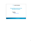
Agilent Technologies
85309A Option H40, H41, H42
Distributed Frequency Converter
0.1 to 18 GHz
Operating and Service
Manual Modification
Use this manual modification with
manual part numbers 85310-90001
(printed August 1993)
Manual part number: 85309-90079
Printed in USA
January 2000
Revision 1.0
Notice
The information contained in this document is subject to change without
notice.
Agilent Technologies makes no warranty of any kind with regard to this
material, including, but not limited to, the implied warranties of
merchantability and fitness for a particular purpose. Agilent Technologies
shall not be liable for errors contained herein or for incidental or
consequential damages in connection with the furnishing, performance, or
use of this material.
Agilent Technologies assumes no responsibility for the use or reliability of
its software on equipment that is not furnished by Agilent Technologies.
This document contains proprietary information which is protected by
copyright. All rights are reserved. No part of this document may be
photocopied, reproduced, or translated to another language without prior
written consent of Agilent Technologies.
RESTRICTED RIGHTS LEGEND
Use, duplication, or disclosure by the U.S. Government is subject to
restrictions as set forth in subparagraph (c)(1)(ii) of the Rights in Technical
Data and Computer Software clause at DFARS 252.227-7013 for DOD
agencies, and subparagraphs (c)(1) and (c)(2) of the Commercial Computer
Software Restricted Rights clause at FAR 52.227-19 for other agencies.
Agilent Technologies, Inc.
1400 Fountain Grove Parkway
Santa Rosa, CA 95403-1799, U.S.A.
© Copyright Agilent Technologies, Inc. 2000
ii Agilent Technologies 85309A Option H40, H41, H42 Operating and Service Manual
What You’ll Find in this Manual . . .
This Agilent Technologies 85309A H40, H41, H42 Operating and Service
Manual Modification provides information specific to these options and in
contrast to the information provided in the Agilent Technologies 85309A
Operating and Service Manual (85309-90001).
All other information contained in the Agilent Technologies 85309A
Operating and Service Manual is still applicable.
Contents
•
Introduction, page 1, provides a description and typical system
performance of the Agilent Technologies 85309A H40, H41, and H42.
•
•
•
Revised Installation, page 3, provides modified installation data.
•
Revised Replaceable Parts, page 11, provides cable, chassis and
replaceable parts lists.
•
Revised Instrument Diagrams, page 17, provides RF block diagrams.
Revised Operations, page 4, provides modified operations.
Revised General Information, page 6, provides modified
specifications.
Agilent Technologies 85309A Option H40, H41, H42 Operating and Service Manual
Warranty
Custom systems are warranted by contractual agreement between Agilent
Technologies and the customer.
Certification
Agilent Technologies, Inc., certifies that this product met its published
specifications at the time of shipment from the factory. Agilent Technologies
further certifies that its calibration measurements are traceable to the
United States National Institute of Standards and Technology (NIST,
formerly NBS), to the extent allowed by the Institute’s calibration facility,
and to the calibration facilities of other International Standards
Organization members.
Warranty
This Agilent Technologies system product is warranted against defects in
materials and workmanship for a period corresponding to the individual
warranty periods of its component products. Instruments are warranted for a
period of one year. During the warranty period, Agilent Technologies will, at
its option, either repair or replace products that prove to be defective.
Warranty service for products installed by Agilent Technologies and certain
other products designated by Agilent Technologies will be performed at
Buyer’s facility at no charge within Agilent Technologies service travel
areas. Outside Agilent Technologies service travel areas, warranty service
will be performed at Buyer’s facility only upon Agilent Technologies’ prior
agreement and Buyer shall pay Agilent Technologies’ round trip travel
expenses. In all other areas, products must be returned to a service facility
designated by Agilent Technologies.
For products returned to Agilent Technologies for warranty service, Buyer
shall prepay shipping charges to Agilent Technologies and Agilent
Technologies shall pay shipping charges to return the product to Buyer.
However, Buyer shall pay all shipping charges, duties, and taxes for products
returned to Agilent Technologies from another country.
Agilent Technologies warrants that its software and firmware designated by
Agilent Technologies for use with an instrument will execute its
programming instructions when properly installed on that instrument.
Agilent Technologies does not warrant that the operation of the instrument,
or software, or firmware will be uninterrupted or error free.
LIMITATION OF WARRANTY. The foregoing warranty shall not apply
to defects resulting from improper or inadequate maintenance by Buyer,
Buyer-supplied software or interfacing, unauthorized modification or
misuse, operation outside of the environmental specifications for the
product, or improper site preparation or maintenance.
iv Agilent Technologies 85309A Option H40, H41, H42 Operating and Service Manual
NO OTHER WARRANTY IS EXPRESSED OR IMPLIED. AGILENT
TECHNOLOGIES SPECIFICALLY DISCLAIMS THE IMPLIED
WARRANTIES OR MERCHANTABILITY AND FITNESS FOR A
PARTICULAR PURPOSE.
EXCLUSIVE REMEDIES. THE REMEDIES PROVIDED HEREIN ARE
BUYER’S SOLE AND EXCLUSIVE REMEDIES. AGILENT
TECHNOLOGIES SHALL NOT BE LIABLE FOR ANY DIRECT,
INDIRECT, SPECIAL, INCIDENTAL, OR CONSEQUENTIAL
DAMAGES, WHETHER BASED ON CONTRACT, TORT, OR ANY
OTHER LEGAL THEORY.
YEAR 2000. Agilent Technologies warrants that each Agilent Technologies
hardware, software, and firmware product on Agilent Technologies’
Corporate Price List (dated July 1, 1998 or later) delivered under the
product’s contract of sale will be able to accurately process date data
(including, but not limited to, calculating, comparing, and sequencing) from,
into, and between the twentieth and twenty-first centuries, and the years
1999 and 2000, including leap year calculations, when used in accordance
with the product documentation provided that all other products (that is,
hardware, software, firmware) used in combination with such Agilent
Technologies product(s) properly exchange date data with it. If the
agreement requires that specific Agilent Technologies products must
perform as a system in accordance with the foregoing warranty, then that
warranty will apply to those Agilent Technologies products as a system, and
Customer retains sole responsibility to ensure the year 2000 readiness of its
information technology and business environment. The duration of this
warranty extends through January 31, 2001.
The remedies available under this warranty will be defined in, and subject to,
the terms and limitations of the warranties contained in the contract of sale.
To the extent permitted by local law, this warranty applies only to branded
Agilent Technologies products and not to products manufacture by others
that may be sold or distributed by Agilent Technologies. Nothing in this
warranty will be construed to limit any rights or remedies provided
elsewhere in the contract of sale with respect to matters other than year 2000
compliance.
Assistance
Product maintenance agreements and other customer assistance agreements
are available for Agilent Technologies products.
For assistance, call your local Agilent Technologies Sales and Service Office
(refer to “Service and Support” on page vi).
Agilent Technologies 85309A Option H40, H41, H42 Operating and Service Manual
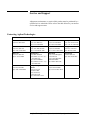
Service and Support
Adjustment, maintenance, or repair of this product must be performed by a
qualified service technician. Please refer to the table below for your nearest
service and support center.
Contacting Agilent Technologies
Online assistance: www.agilent.com/find/assist
United States
(tel) 1 800 452 4844
Latin America
(tel) (305) 269 7500
(fax) (305) 269 7599
Canada
(tel) 1 877 894 4414
(fax) (905) 282-6495
Europe
(tel) (+31) 20 547 2323
(fax) (+31) 20 547 2390
New Zealand
(tel) 0 800 738 378
(fax) (+64) 4 495 8950
Japan
(tel) (+81) 426 56 7832
(fax) (+81) 426 56 7840
Australia
(tel) 1 800 629 485
(fax) (+61) 3 9210 5947
Singapore
(tel) 1 800 375 8100
(fax) (65) 836 0252
Malaysia
(tel) 1 800 828 848
(fax) 1 800 801 664
Philippines
(tel) (632) 8426802
(tel) (PLDT subscriber only):
1 800 16510170
(fax) (632) 8426809
(fax) (PLDT subscriber only):
1 800 16510288
Thailand
(tel) outside Bangkok:
(088) 226 008
(tel) within Bangkok:
(662) 661 3999
(fax) (66) 1 661 3714
Hong Kong
(tel) 800 930 871
(fax) (852) 2506 9233
Taiwan
(tel) 0800-047-866
(fax) (886) 2 25456723
People’s Republic of
China
(tel) (preferred):
800-810-0189
(tel) (alternate):
10800-650-0021
(fax) 10800-650-0121
India
(tel) 1-600-11-2929
(fax) 000-800-650-1101
vi Agilent Technologies 85309A Option H40, H41, H42 Operating and Service Manual
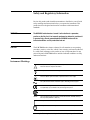
Safety and Regulatory Information
Review this product and related documentation to familiarize yourself with
safety markings and instructions before you operate the instrument. This
product has been designed and tested in accordance with international
standards.
WARNING
The WARNING notice denotes a hazard. It calls attention to a procedure,
practice, or the like, that, if not correctly performed or adhered to, could result
in personal injury. Do not proceed beyond a WARNING notice until the
indicated conditions are fully understood and met.
CAUTION
The CAUTION notice denotes a hazard. It calls attention to an operating
procedure, practice, or the like, which, if not correctly performed or adhered
to, could result in damage to the product or loss of important data. Do not
proceed beyond a CAUTION notice until the indicated conditions are fully
understood and met.
Instrument Markings
!
When you see this symbol on your instrument, you should refer to the instrument’s
instruction manual for important information.
This symbol indicates hazardous voltages.
The laser radiation symbol is marked on products that have a laser output.
This symbol indicates that the instrument requires alternating current (ac) input.
The CE mark is a registered trademark of the European Community. If it is
accompanied by a year, it indicates the year the design was proven.
The CSA mark is a registered trademark of the Canadian Standards Association.
1SM1-A
This text indicates that the instrument is an Industrial Scientific and Medical Group 1
Class A product (CISPER 11, Clause 4).
This symbol indicates that the power line switch is ON.
This symbol indicates that the power line switch is OFF or in STANDBY position.
Agilent Technologies 85309A Option H40, H41, H42 Operating and Service Manual
Safety Earth
Ground
This is a Safety Class I product (provided with a protective earthing
terminal). An uninterruptible safety earth ground must be provided from the
main power source to the product input wiring terminals, power cord, or
supplied power cord set. Whenever it is likely that the protection has been
impaired, the product must be made inoperative and secured against any
unintended operation.
Before Applying Power
Verify that the product is configured to match the available main power
source as described in the input power configuration instructions in this
manual. If this product is to be powered by autotransformer, make sure the
common terminal is connected to the neutral (grounded) side of the ac power
supply.
viii Agilent Technologies 85309A Option H40, H41, H42 Operating and Service Manual
Typeface Conventions
•
Used to emphasize important information:
Use this software only with the Agilent Technologies .
•
Used for the title of a publication:
Refer to the Agilent Technologies 85309A Option H40, H41, H42
Operating and Service Manual Modification.
•
Used to indicate a variable:
Type LOAD BIN filename.
Instrument Display
•
Used to show on-screen prompts and messages that you will see on the
display of an instrument:
The Agilent Technologies will display the message CAL1 SAVED.
[Keycap]
•
Used for labeled keys on the front panel of an instrument or on a
computer keyboard:
Press [Return].
{Softkey}
•
Used for simulated keys that appear on an instrument display:
Press {Prior Menu}.
User Entry
•
Used to indicate text that you will enter using the computer keyboard;
text shown in this typeface must be typed exactly as printed:
Type LOAD PARMFILE
•
Used for examples of programming code:
Italics
#endif // ifndef NO_CLASS
Path Name
•
Used for a subdirectory name or file path:
Edit the file usr/local/bin/sample.txt
Computer Display
•
Used to show messages, prompts, and window labels that appear on a
computer monitor:
The Edit Parameters window will appear on the screen.
•
Used for menus, lists, dialog boxes, and button boxes on a computer
monitor from which you make selections using the mouse or keyboard:
Double-click EXIT to quit the program.
Agilent Technologies 85309A Option H40, H41, H42 Operating and Service Manual
x Agilent Technologies 85309A Option H40, H41, H42 Operating and Service Manual
Introduction
Introduction
This operating and service manual modification describes the differences in
the Agilent Technologies 85309A H40, H41 and H42 options compared to
the standard Agilent Technologies 85309A option 001 LO/IF distribution
unit. It also describes the manual changes necessary to document the Agilent
Technologies 85309A H40, H41 and H42.
Description
The Agilent Technologies 85309A H40, H41 and H42 are broadband,
distributed frequency converters that utilize fundamental mixing to provide
the performance required for antenna measurement systems. The
Agilent Technologies 85309A H40, H41 and H42 have one reference
channel, up to three test channels, and operate from 100 MHz to 18 GHz in
two overlapping bands, as follows:
Band
Operating Frequency
Low band
0.1 to 1 GHz
High band
0.3 to 18 GHz
The measurement bands can be selected manually from the instrument’s
front panel BAND SELECT switch or the TTL interface provided at the rear
panel SELECT port for automated control.
Option Definition
The Agilent Technologies 85309A H40, H41 and H42 are distinguished by
the number of test channels available, as follows:
Option
Number of Test Channels
Agilent Technologies 85309A H40
1
Agilent Technologies 85309A H41
2
Agilent Technologies 85309A H42
3
NOTE
Use Agilent Technologies 85320A/B option H20 external mixer modules to
utilize the 0.1 to 3 GHz frequency range of operation.
Agilent Technologies
8836xx Series LO
Source Operation Note
When using an Agilent Technologies 8360 series synthesized sweeper as the
LO source, set the output power level to approximately +10 dBm in order to
minimize potential Agilent Technologies 85310A system-generated spurious
signals in the 0.1 to 3 GHz range.
Agilent 85309A H40, H41, H42 Operating and Service Manual Modification 1
Introduction
The spurious signal levels seen on the Agilent Technologies 8510/30 depend
on the LO power level setting.
•
At the recommended +10 dBm setting, spur levels should be no greater
than –100 dB.
•
With a power level of as much as +23 dBm, spurs may be detected as
high as –60 dB.
2 Agilent 85309A H40, H41, H42 Operating and Service Manual Modification
Revised Installation
Revised Installation
The following modifies the “Installation” section of the Agilent Technologies
85309A Operating and Service Manual, pages 2-5 through 2-7.
ac Power Connections
No line voltage selector setting is required. The ac input power that the
option H40, H41, and H42 can accept is 90 to 132 Vac or 198 to 264 Vac at
50-60 Hz.
Fuse Type
4 A (2110-0680)
Agilent 85309A H40, H41, H42 Operating and Service Manual Modification 3
Revised Operations
Revised Operations
The following modifies the “Operations” section of the Agilent Technologies
85309A Operating and Service Manual, page 3-2 through 3-4.
Front and Rear Panel
Feature Changes
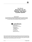
A green LED on the instrument’s front panel (left side) indicates which
measurement band has been selected. LED ON indicates HIGH BAND has
been selected and LED OFF indicates LOW BAND has been selected.
Figures 1 and 2 show typical front and rear panels.
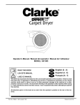
By setting the front panel BAND SELECT switch to the EXTernal position
for automated control, the rear panel SELECT port can be used to perform
band selection. A TTL High (+5 V), LED ON, selects HIGH BAND and a
TTL (0 V), LED OFF, selects LOW BAND.
Figure 1
Typical front panel (Agilent Technologies 85309A H40)
Figure 2
Typical rear panel (Agilent Technologies 85309A H40)
4 Agilent 85309A H40, H41, H42 Operating and Service Manual Modification
Revised Operations
All rear panel functional descriptions are the same for the HIGH or LOW
band operations.
J15 Rear Panel Port, HIGH/LOW BAND SELECT
When the front panel BAND SELECT switch is set to EXT, this port can be
used to select the operating band desired by the following TTL levels:
HIGH BAND: > + 4 Vdc
LOW BAND: < 0.5 Vdc
J7 and J8 (using nondiplexed mixers)
These two rear panel ports are not available on the Agilent Technologies
85309A H40, H41, and H42 options.
Agilent 85309A H40, H41, H42 Operating and Service Manual Modification 5
Revised General Information
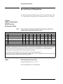
Revised General Information
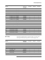
The following general information supersedes “General Information, Table
5-3”, in the Agilent Technologies 85310A Operating and Service Manual.
Typical
Agilent Technologies
85301B System
Performance Data
Table 1
Typical Agilent Technologies 85301B System Performance Data with
Agilent Technologies 85309A H40, H41, H42
Table 5-3a
Specification (Typical)
a
Sensitivity
b
Compression Level
(S/N=1, 0 average)
(at 0.1 dB)
GHz
*0.1 - 0.3 *0.3 - 0.8
*0.8 - 1
**0.3 - 3
2-3
3 - 18
***6 - 20 ***20 - 26.5
-dBm
110
110
110
110
115
115
105
100
-dBm
20
20
20
20
20
20
15
15
c
Dynamic Range
dB
90
90
90
90
95
95
90
85
d
Channel Isolation
dB
100
95
90
105
110
105
110
105
Minimum phase lock power
-dB
55
55
55
55
55
55
55
55
RF Port match (2.0:1 max)
dB
8
8
8
8
8
8
8
8
e
* w/85320A/B H20 mixer, Low Band; ** w/85320A/B H20, High Band; *** 3rd Harm. Mode
a Sensitivity is the calculated difference between IF noise and RF/IF conversion gain/loss. Averaging will improve sensitivity by 10 log (avg. factor).
b RF level for 0.1 dB compression: the RF input level where the RF and the IF levels are no longer tracking each other linearly within 0.1dB.
c Dynamic range is the calculated difference between 0.1 dB compression and sensitivity.
d Crosstalk is the coherent RF leakage from the reference ch3annel to the test channel with 1024 averages.
e Refers to systems that use an Agilent Technologies 8350 LO source. Minimum phase lock power is the minimum RF power into the reference mixer
to achieve phase lock. This does not apply to systems with a synthesized LO.
Other
Environmental Characteristics
Operating conditions: 0 °C to + 50 °C
Power consumption: 310 Vac (maximum)
6 Agilent 85309A H40, H41, H42 Operating and Service Manual Modification
Revised General Information
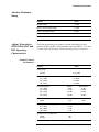
Absolute Maximum
Rating
Parameter
Agilent Technologies
85309A H40, H41, and
H42 Operating
Characteristics
Values
LO input port (CW)
+ 23 dBm
Reference channel IF input port (CW)
+ 13 dBm
Reference channel detector input
± 20 vdc
Pos. Z blanking input
± 10 vdc
Select HI/LOW input
± 5.5 vdc
The following parameters are unique to Agilent Technologies 85309A
options H40, H41 and H42. These parameters supersede Tables 5-5, 5-6, and
5-7 in the Agilent Technologies 85310A Operating and Service Manual.
Nominal Channel
Performance
Parameter
Values
Frequency range:
Low band
High band
0.1 to 1.0 GHz
0.3 to 18 GHz
Input power range (LO input recommended):
0.1 to 1.0 GHz
0.3 to 3.0 GHz
2.0 to 18 GHz
6 to 10 dBm
6 to 10 dBm
0 to 6 dBm
Power output (LO ports):
Minimum
Typical minimum
0.1 to 1.0 GHz
0.3 to 0.5 GHz
0.5 to 3.0 GHz
3.0 to 6.2 GHz
6.2 to 18 GHz
14 dBm
21.2 dm
22.1 dBm
24.1 dBm
21.5 dBm
15 dBm
24.2 dBm
24.5 dBm
26.5 dBm
24 dBm
Minimum
Maximum
21 dB
25 dB
IF channel small signal gain:
20 MHz
Output power channel tracking (typical):
0.1 to 1.0 GHz
0.3 to 3.0 GHz
2.0 to 18 GHz
± 1.3 dB
± 2 dB
± 2 dB
Port return loss, 0.1 to 18 GHz typical:
LO input
LO output
9 dB
7 dB
Agilent 85309A H40, H41, H42 Operating and Service Manual Modification 7
Revised General Information
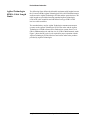
Agilent Technologies
85381A Cable Length
Limits
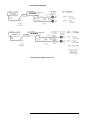
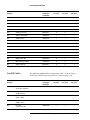
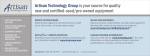
The following figure defines the allowable maximum cable lengths between
the LO source and the Agilent Technologies 85309A LO/IF distribution unit,
and between the Agilent Technologies 85309A and the external mixers. The
cable lengths are provided when using standard Agilent Technologies
85381A RF cable assemblies and with MicroCoax type UFB311A RF
low-loss cable assemblies.
The standard mixers used in Agilent Technologies antenna measurement
systems are the Agilent Technologies 85320A test mixer and the Agilent
Technologies 85320B reference mixer. Both mixers operate from 2 to 18
GHz in fundamental mode, and from 6 to 26.5 GHz in third-harmonic mode.
Figure 3 shows the RF power levels required for proper operation with the
Agilent Technologies 85320A/B mixers and various other mixer products
provided by Agilent Technologies.
8 Agilent 85309A H40, H41, H42 Operating and Service Manual Modification
Revised General Information
Figure 3
Cable Length Configurations (1 of 2)
Agilent 85309A H40, H41, H42 Operating and Service Manual Modification 9
Revised General Information
Cable Length Configurations (2 of 2)
10 Agilent 85309A H40, H41, H42 Operating and Service Manual Modification
Revised Replaceable Parts
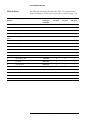
Revised Replaceable Parts
Agilent Technologies
85309A H40, H41, H42
Major Assemblies
The following replaceable parts list supersedes Table 7-19 in the Agilent
Technologies 85309A Operating and Service Manual (page 7-58). Refer to
Figures 3, 4, and 5.
Reference
Designator
Description
Agilent
Technologies
Part Number
Quantity
H40 option
Quantity
H41 option
Quantity
H42 option
A1
PC board, front panel display
85309-60022
1
1
1
A2
PC board, ALC/REG
85309-60093
1
1
1
A3
PC board, switch control
85309-60040
1
1
1
A4
PC , remote applications
85309-60047
1
1
1
A5
PC board, dc power distribution
85309-60098
1
1
1
A10
Low pass filter, 30 MHz
---
1
1
1
A11
Power divider, 18 GHz, 4-way
0955-0566
1
1
1
A12
RF amplifier, 0.3 to 18 GHz (Ref Chan)
5087-7055
1
1
1
A13
RF amplifier, 0.3 to 18 GHz (Test1 Chan)
5087-7055
1
1
1
A14
IF amplifier, 0.5 to 500 MHz (Ref Chan)
0955-0511
1
1
1
A15
IF amplifier, 0.5 to 500 MHz (Test1 Chan)
0955-0511
1
1
1
A16
Diplexer, (Test1 Chan)
5086-7542
1
1
1
A17
RF amplifier, 0.3 to 18 GHz (Input)
5086-7530
1
1
1
A18
Kit assembly, LO Power Adjustment
85309-60031
1
1
1
A20
Kit assembly, LO Power indicator
85309-60032
1
1
1
A22
dc power supply, -15, +5, +15, +24
85309-80019
1
1
1
A23
dc power supply, +15 @10A
85309-80020
1
1
1
A24
RF amplifier, 0.3 to 18 GHz (Test2 Chan)
5087-7055
0
1
1
A25
Diplexer, (Test2 Chan)
5086-7542
0
1
1
A26
IF amplifier, 0.5 to 500 MHz (Test2 Chan)
0955-0511
0
1
1
A27
RF amplifier, 0.3 to 18 GHz (Test3 Chan)
5087-7055
0
0
1
A28
Diplexer, (Test3 Chan)
5086-7542
0
0
1
A29
IF amplifier, 0.5 to 500 MHz (Test3 Chan)
0955-0511
0
0
1
A30
RF amplifier, 10 to 1200 MHz
85309-80014
1
1
1
A31
RF amplifier, 10 to 1000 MHz
85309-80015
1
1
1
Agilent 85309A H40, H41, H42 Operating and Service Manual Modification 11
Revised Replaceable Parts
Reference
Designator
Description
Agilent
Technologies
Part Number
Quantity
H40 option
Quantity
H41 option
Quantity
H42 option
A32
Power divider, 1 GHz, 4way
85309-80022
1
1
1
A36
Filter, 100 MHz high-pass (Ref. Chan)
85309-80012
1
1
1
A37
Filter, 100 MHz high-pass (Test1 Chan)
85309-80012
1
1
1
A38
Filter, 100 MHz high-pass (Test2 Chan)
85309-80012
0
1
1
A39
Connection adapter, SMA m/f RT Ang (Ref.
Chan)
1250-1249
1
1
1
A40
Connection .adapter, SMA m/f RT Ang (Test1
Chan)
1250-1249
1
1
1
A41
Connection adapter, SMA m/f RT Ang (Test2
Chan)
1250-1249
0
1
1
A42
Connection adapter, SMA m/f RT Ang (Test3
Chan)
1250-1249
0
0
1
A43
Filter, 30 MHz low-pass (Test1 Chan)
85110-80015
1
1
1
A44
Filter, 30 MHz low-pass (Test2 Chan)
85110-80015
0
1
1
A45
Filter, 30 MHz low-pass (Test3 Chan)
85110-80015
0
0
1
A46
Filter, 100 MHz high-pass (Test3 Chan)
85309-80012
0
0
1
AT1
Coax attenuator, sloped (Test2 Chan)
33340CZ
0
1
1
AT2
Coax attenuator, sloped (Test3 Chan)
33340CZ
0
0
1
AT3
Coax attenuator, sloped (Test2 Chan)
33340CZ
1
1
1
AT4
Coax attenuator, sloped (Ref. Chan)
33340CZ
1
1
1
AT5
Coax termination, 50 ohm, SMB(f)
1250-0676
1
1
1
AT6
Coax termination,50 ohm, SMA(m)
0955-0053
1
1
0
AT7
Coax attenuator, 1dB (Ref. Chan)
0955-0321
1
1
1
AT8
Coax attenuator, 1dB (Test1. Chan)
0955-0321
1
1
1
AT9
Coax attenuator, 1dB (Test2. Chan)
0965-0321
0
1
1
AT10
Coax attenuator, 10 dB
0955-0122
1
1
1
AT11
Coax attenuator, 1dB (Test3. Chan)
0965-0321
0
0
1
AT12
Coax termination, 50 ohm, SMA(m)
0960-0053
1
1
0
AT13
Coax termination, 50 ohm, SMA(m)
0960-0053
1
0
0
AT14
Coax termination, 50 ohm, SMA(m)
0960-0053
1
0
0
B1
Fan, 24 vdc
08760-82031
1
1
1
FL1
ac line filter
85309-80021
1
1
1
J1
Coax bulkhead connector, N(f)/SMA(f)
86290-60005
1
1
1
J2
Coax bulkhead connector, N(f)/SMA(f)
86290-60005
1
1
1
12 Agilent 85309A H40, H41, H42 Operating and Service Manual Modification
Revised Replaceable Parts
Reference
Designator
Description
Agilent
Technologies
Part Number
Quantity
H40 option
Quantity
H41 option
Quantity
H42 option
J3
Coax bulkhead connector, N(f)/SMA(f)
86290-60005
1
1
1
J4
Coax bulkhead connector, N(f)/SMA(f)
86290-60005
1
1
1
J5
Coax bulkhead connector, N(f)/SMA(f)
86290-60005
1
1
1
J6
Coax bulkhead connector, N(f)/SMA(f)
86290-60005
1
1
1
J9
Coax bulkhead connector, N(f)/SMA(f)
86290-60005
1
1
1
J10
Coax bulkhead connector, N(f)/SMA(f)
86290-60005
1
1
1
J11
Coax bulkhead connector, N(f)/SMA(f)
86290-60005
0
1
1
J12
Coax bulkhead connector, N(f)/SMA(f)
86290-60005
0
1
1
J13
Coax bulkhead connector, N(f)/SMA(f)
86290-60005
0
0
1
J14
Coax bulkhead connector, N(f)/SMA(f)
86290-60005
0
0
1
J15
Coax bulkhead connector, BNC(f)
1250-0118
1
1
1
SW1
Switch, SPDT (part of W24 assy)
3101-0449
1
1
1
SW2
Switch, SP3T, rotary
3100-3244
1
1
1
SW3
Switch, RF SPDT, 15 Vdc 18 GHz
8762B #015
1
1
1
SW4
Switch, RF SPDT, 15 Vdc 18 GHz
8762B #015
1
1
1
SW5
Switch, RF SPDT, 15 Vdc 18 GHz
8762B #015
1
1
1
SW6
Switch, RF SPDT, 15 Vdc 18 GHz
8762B #015
0
1
1
SW7
Switch, RF SPDT, 15 Vdc 18 GHz
8762B #015
0
0
1
RF Cables
The following standard cables list supercedes Table 7-22 in the Agilent
Technologies 85309A Operating and Service Manual (page 7-66).
Reference
Designator
Description
Agilent
Technologies
Part Number
Quantity
H40 option
Quantity
H41 option
Quantity
H42 option
W1
RP(J1) to SW3(C)
85309-20100
1
1
1
W2
SW3(2) to A17 In
85309-20101
1
1
1
W3
A17 Out to A11 Input
85309-20102
1
1
1
W4
A11 Out (AT3) to A12 In
85309-20103
1
1
1
W5
A11 Out (AT4) to A13 In
85309-20104
1
1
1
W6
A13 Out to SW5 (2)
85309-20105 1
1
1
1
W7
A16 Out to RP(J3)
85309-20106 1
1
1
1
W9
A12 Out to SW4(2)
85309-20107 1
1
1
1
Agilent 85309A H40, H41, H42 Operating and Service Manual Modification 13
Revised Replaceable Parts
Reference
Designator
Description
Agilent
Technologies
Part Number
Quantity
H40 option
Quantity
H41 option
Quantity
H42 option
W30
A11 Out (AT1) to A24 In
85309-20108
0
1
1
W31
A24 Out to SW6 (2)
85309-20109 1
0
1
1
1
0
1
1
W32
A25 LO/IF to RP (J11)
85309-20110
W35
A11 Out(AT2) to A27 In
85309-20111
0
0
1
W36
A27 Out to SW7 (2)
85309-20112 1
0
0
1
W37
A28 LO/IF to RP (J13)
85309-20113 1
0
0
1
W41
SW3(1) to A30 In (AT10)
85309-20114
1
1
1
W42
A30 Out to A31 In
85309-20115
1
1
1
W43
A31 Out to A32 In(S)
85309-20116
1
1
1
W44
AT7 (A32-1 Out) to SW4 (1)
85309-20117
1
1
1
W45
AT8(A32-3 Out) to SW5 (1)
85309-20118
1
1
1
W46
SW4(C) to RP(J2)
85309-20119 1
1
1
1
W47
SW5(C) to A16 LO
85309-20120 1
1
1
1
W48
AT9(A32-2 Out) to SW6(1)
85309-20121
0
1
1
0
1
1
1
W49
SW6(C) to A25 LO In
85309-20122
W50
AT11(A32-4 Out) to SW7(1)
85309-20123
0
0
1
W51
SW7(C) to A28 LO
85309-20124 1
0
0
1
1. Special low loss cable assembly done by SRC Cable Company.
Non-RF Cables
Reference
Designator
Description
W8
The following standard cables list supersedes Table 7-23 in the Agilent
Technologies 85309A Operating and Service Manual (page 7-68).
Agilent
Technologies
Part Number
Quantity
H40 option
Quantity
H41 option
Quantity
H42 option
Coax, flex/
A16 I.F. Out to A43(A15 In)
8120-5531
1
1
1
W11
Coax, flex, Test1 IF signal/
A15 Out to RP(J9)
08760-63404
1
1
1
W12
Coax, flex/
RP(J4) to A10 In
8120-5107
1
1
1
W13
Coax, flex/
A10 Out to A14 In
8120-5107
1
1
1
W14
Coax, flex/
A14 Out to RP(J10)
08760-62356
1
1
1
14 Agilent 85309A H40, H41, H42 Operating and Service Manual Modification
Revised Replaceable Parts
Reference
Designator
Description
Agilent
Technologies
Part Number
Quantity
H40 option
Quantity
H41 option
Quantity
H42 option
W15
Coax, flex, Ref IF signal/
A2(J1) to RP(J5)
8120-6118
1
1
1
W16
Coax, flex, PosZ signal/
A2(J2) to RP(J6)
8120-6118
1
1
1
W17
Ribbon, FP display intrface/
A2(J6) to A1(J1)
85309-60055
1
1
1
W18
Ribbon, Dual RF Amp dc Pwr/
A2(J3) to A12,13 BiasBd.(J1)
85309-60058
1
1
1
W19
Ribbon, Dual RF Amp dc Pwr/
A2(J4) to A24,27 BiasBd.(J1)
85309-60059
0
1
1
W20
Ribbon, Input RF Amp dc Pwr/
A2(J5) to A17 BiasBd.(J1)
85309-60050
1
1
1
W21
Wire Harness, dc Pwr Intrfc/
A22 to A2(J7),A5(J1)
85309-60057
1
1
1
W22
Wire Harness, IF Amp dc Pwr/
A2(J9) to A15(+15v)
85309-60053
1
1
1
W23
Wire Harness, IF Amp dcPwr/
A2(J8) to A14(+15v)
85309-60053
1
1
1
W24
Wire Harness, ac Pwr Intrfc/
AC switch assy
85309-60056
1
1
1
W25
Coax, flex/
A2(J12) to A4(J5)
8120-5021
1
1
1
W26
Coax, flex/
A4(J5) – A17 BiasBd.(J2)
8120-5024
1
1
1
W27
Coax, flex/
A4(J6) – A30 (ALC)
85309-60060
1
1
1
W28
Wire Harness, IF Amp dc Pwr/
A2(J13) to A26(+15v)
85309-60053
0
1
1
W29
Wire harness, IF Amp dc Pwr/
A2(J14) to A29(+15v)
85309-60053
0
0
1
W33
Coax, flex/
A25 I.F. Out to A26 In
8120-5531
0
1
1
W34
Coax, flex, Test2 IF signal/
A26 Out to RP(J12)
08760-63404
0
1
1
W38
Coax, flex/
A28 I.F. Out to A29 In
8120-5054
0
0
1
W39
Coax, flex, Test3 IF signal/
A29 Out to RP(J14)
08760-63404
0
0
1
W40
Wire harness, dc Pwr Intrfc/
A23 to A2(P1)
85309-60052
1
1
1
Agilent 85309A H40, H41, H42 Operating and Service Manual Modification 15
Revised Replaceable Parts
Chassis Parts
Reference
Designator
The following chassis parts list supersedes Table 7-25 contained in the
Agilent Technologies 85309A Operating and Service Manual (page 7-72).
Description
Agilent
Technologies
Part Number
Quantity
H40 option
Quantity
H41 option
Quantity
H42 option
Bracket, switch-mount
33311-02005
2
3
4
1
Cover, top-perforated
08513-00040
1
1
1
6
Cover, side-perforated
08513-00041
1
1
1
7
Cover, side-perforated
08513-00041
1
1
1
A3 & A4
boards
Housing assembly
08513-60156
1
1
1
6960-0028
4
2
0
Hole plug
13
Subpanel, front
85309-00028
1
1
1
14
Panel, rear
85309-00051
1
1
1
15
Main deck
85309-00053
1
1
1
16
H40 front panel, dress
85309-00052
1
0
0
16
H41 front panel, dress
85309-00046
0
1
0
16
H42 front panel, dress
85309-000
0
0
1
23
Fan, 28 vdc
08760-82031
1
1
1
24
Finger guard, fan
08760-82032
1
1
1
Bracket, fan duct
85309-00050
1
1
1
Bracket, input amp/switch mount
85309-00054
1
1
1
Bracket, power divider mount
85309-00055
1
1
1
Bracket, diplexers mount
85309-00056
1
1
1
Bracket, LPF A10 mount
85309-00057
1
1
1
16 Agilent 85309A H40, H41, H42 Operating and Service Manual Modification
Revised Instrument Diagrams
Revised Instrument Diagrams
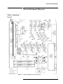
Major Components
Layout
Figure 4
Major Components Layout Locations
Agilent 85309A H40, H41, H42 Operating and Service Manual Modification 17
Revised Instrument Diagrams
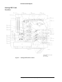
Semirigid RF Cable
Locations
Figure 5
Semirigid RF Cable Locations
18 Agilent 85309A H40, H41, H42 Operating and Service Manual Modification
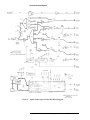
Revised Instrument Diagrams
Agilent Technologies
85309A H40
Major Assembly Block
Diagram
For the Agilent Technologies 85309A H40, Figure 3, replaces Figure 7-24 in
the Agilent Technologies 85309A Operating and Service Manual
(pages 7-65).
Agilent 85309A H40, H41, H42 Operating and Service Manual Modification 19
Revised Instrument Diagrams
Figure 6
Agilent Technologies 85309A H40 Block Diagram
20 Agilent 85309A H40, H41, H42 Operating and Service Manual Modification
Revised Instrument Diagrams
Agilent Technologies
85309A H41
Major Assembly Block
Diagram
For the Agilent Technologies 85309A H41, Figure 4, replaces Figure 7-24 in
the Agilent Technologies 85309A Operating and Service Manual
(pages 7-65).
Agilent 85309A H40, H41, H42 Operating and Service Manual Modification 21
Revised Instrument Diagrams
Figure 7
Agilent Technologies 85309A H41 Block Diagram
22 Agilent 85309A H40, H41, H42 Operating and Service Manual Modification
Revised Instrument Diagrams
Agilent Technologies
85309A H42
Major Assemblies
Block Diagram
For the Agilent Technologies 85309A H42, Figure 8, replaces Figure 7-24 in
the Agilent Technologies 85309A Operating and Service Manual
(pages 7-65).
Agilent 85309A H40, H41, H42 Operating and Service Manual Modification 23
Revised Instrument Diagrams
Figure 8
Agilent Technologies 85309A H42 Block Diagram
24 Agilent 85309A H40, H41, H42 Operating and Service Manual Modification