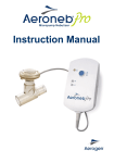
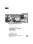
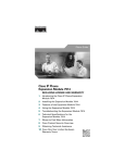
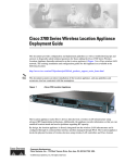
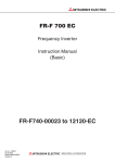
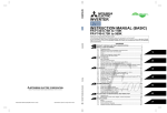
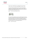
1
Quick Start Guide
Cisco Aironet 1000 Series Lightweight Access Points
INCLUDING LICENSE AND WARRANTY
1
About this Guide
2
Safety Information
3
Introduction to the Access Point
4
Unpacking the Access Point
5
Installing and Deploying the Access Point
6
In Case of Difficulty
7
Obtaining Documentation
8
Documentation Feedback
9
Cisco Product Security Overview
10 Obtaining Technical Assistance
11 Obtaining Additional Publications and Information
12 Cisco One-Year Limited Hardware Warranty Terms
1 About this Guide
This guide is designed to help you install and minimally configure your Cisco Aironet 1000 Series
Lightweight Access Point in a wireless Local Area Network (LAN). This guide covers both the internal
and external models of the access point.
For additional installation, mounting, and configuration information for the access point, see the
following documents:
• Cisco Aironet 1000 Series Lightweight Access Point Hardware Installation Guide
• Cisco Wireless LAN Controller Configuration Guide
These and other documents are available on Cisco.com. Follow these steps to access these documents:
Step 1
Browse to http://www.cisco.com
Step 2
Click Technical Support and Documentation.
Step 3
Click Wireless. The Wireless Support Resources page appears.
Step 4
Choose the appropriate link for the documents you want to view or download.
2 Safety Information
Follow the guidelines in this section to ensure proper operation and safe use of the access point.
FCC Safety Compliance Statement
The FCC with its action in ET Docket 96-8 has adopted a safety standard for human exposure to radio
frequency (RF) electromagnetic energy emitted by FCC certified equipment. When used with approved
Cisco Aironet antennas, Cisco Aironet products meet the uncontrolled environmental limits found in
OET-65 and ANSI C95.1, 1991. Proper installation of this radio according to the instructions found in
this manual will result in user exposure that is substantially below the FCC recommended limits.
Declaration of Conformity with Regard to the EU Directive 1999/5/EC (R&TTE
Directive)
This declaration is only valid for configurations (combinations of software, firmware and hardware)
provided and/or supported by Cisco Systems. The use software or firmware not supported/provided
by Cisco Systems may result that the equipment is no longer compliant with the regulatory
requirements.
2
General Safety Guidelines
Do not hold any component containing a radio so that the antenna is very close to or touching any
exposed parts of the body, especially the face or eyes, while transmitting.
Warnings
Safety warnings appear throughout this guide in procedures that may harm you if performed
incorrectly. A warning symbol precedes each warning statement. The warnings below are general
warnings that are applicable to the entire guide.
Translated versions of the safety warnings in this guide are provided in the Safety Warnings for Cisco
Aironet 1000 Series Access Points document that accompanies this guide. The translated warnings are
also in Appendix A of the Cisco Aironet 1000 Series Lightweight Access Point Hardware Installation Guide,
which is available at cisco.com.
Warning
This warning symbol means danger. You are in a situation that could cause bodily injury.
Before you work on any equipment, be aware of the hazards involved with electrical
circuitry and be familiar with standard practices for preventing accidents. Use the
statement number provided at the end of each warning to locate its translation in the
translated safety warnings that accompanied this device. Statement 1071
SAVE THESE INSTRUCTIONS
Warning
Do not operate your wireless network device near unshielded blasting caps or in an
explosive environment unless the device has been modified to be especially qualified for
such use.
Statement 245B
Warning
In order to comply with FCC radio frequency (RF) exposure limits, antennas should be
located at a minimum of 7.9 inches (20 cm) or more from the body of all persons.
Statement 332
Warning
This product must be connected to a power-over-ethernet (PoE) IEEE 802.3af compliant
power source or an IEC60950 compliant limited power source. Statement 353
3
Warning
Do not work on the system or connect or disconnect cables during periods of lightning
activity. Statement 1001
Warning
Read the installation instructions before you connect the system to its power source.
Statement 1004
Warning
This product relies on the building’s installation for short-circuit (overcurrent)
protection. Ensure that the protective device is rated not greater than: 20A
Statement 1005
3 Introduction to the Access Point
The Cisco Aironet 1000 series lightweight access points combine mobility and flexibility with the
enterprise-class features required by networking professionals. These access points are part of the
Cisco Integrated Wireless Network Solution and require no manual configuration before they are
mounted. The access point is automatically configured by a Cisco Wireless LAN Controller (hereafter
called a controller) using the Lightweight Access Point Protocol (LWAPP).
Three models of the access point are available and are described in Table 1.
Table 1
Available 1000 Series Access Point Models
Model
Description
AP 1010
Two integrated patch antennas
AP 1020
Two integrated diversity patch antennas and two external antenna connectors
AP 1030
Two integrated patch antennas and one external antenna connector
The integrated antennas are supplied with the access point. You must supply the external antennas for
the AP 1020 and AP 1030 models. See your Cisco sales representative for additional information.
External antennas must be mounted indoors only.
The access point contains two integrated radios: a 2.4-GHz radio (IEEE 802.11g) and a 5-GHz radio
(IEEE 802.11a). Using a controller, you can configure the radios separately with different settings on
each. In the Cisco Centralized Wireless LAN architecture, access points operate in the lightweight
4
mode (as opposed to autonomous mode). The access points associate to a controller. The controller
manages the configuration, firmware, and control transactions such as 802.1x authentication. In
addition, all wireless traffic is tunneled through the controller.
LWAPP is an Internet Engineering Task Force (IETF) draft protocol that defines the control messaging
for setup and path authentication and run-time operations. LWAPP also defines the tunneling
mechanism for data traffic. In an LWAPP environment, a lightweight access point discovers a
controller by using LWAPP discovery mechanisms and then sends it an LWAPP join request. The
controller sends the access point an LWAPP join response allowing the access point to join the
controller. When the access point joins the controller, it attempts to download a new operating system
software if the versions on the access point and controller do not match. After an access point joins a
controller, you can reassign it to any controller on your network.
LWAPP secures the control communication between the access point and controller by means of a
secure key distribution, utilizing X.509 certificates on both the access point and controller.
The Controller Discovery Process
Lightweight access points must be discovered by a wireless LAN controller before they can become an
active part of the network. Once an access point is discovered, the controller manages its
configuration, firmware, control transactions, and data transactions. When you connect a 1000 series
access point to your network and apply power, the following discovery process occurs:
1. The access point sends an LWAPP discovery request message.
2. Wireless LAN controllers receiving the request respond with an LWAPP discovery response.
3. The access point selects a controller to join from the discovery responses it receives.
4. The access point sends an LWAPP join request message to the selected controller, expecting an
LWAPP join response.
5. The controller receives the join request and responds with an LWAPP join response. The join
process includes mutual authentication and encryption key derivation which is used to secure the
join process and future LWAPP control messages.
6. The access point joins the controller and begins exchanging LWAPP messages. The access point
compares its firmware with that residing on the controller. If a version mismatch is detected, the
access point downloads the controller’s firmware.
7. After the controller and access point synchronize firmware versions, the controller provisions the
access point with the appropriate configuration settings, which include SSIDs, security
parameters, and 802.11 parameters such as data rates, supported PHY types, radio channels, and
power levels.
8. When provisioning is completed, the access point and controller enter the LWAPP run-time state
and begin servicing data traffic.
5
9. During run-time operations, the controller may issue various commands to the access point via
LWAPP control messages. Examples of these commands are other provisioning commands or
requests for statistical information collected and maintained by the access point.
10. During run-time operations, LWAPP keep-alive messages are exchanged between the access point
and controller to preserve the LWAPP communication channel. When a sufficient number of
keep-alive are missed by the access point, it attempts to discover a new controller.
For more information about the LWAPP discovery process and the various discovery methods, see the
Cisco Wireless LAN Controller Configuration Guide. This guide is available on cisco.com.
4 Unpacking the Access Point
Follow these steps to unpack the access point:
Step 1
Open the shipping container and carefully remove the contents.
Step 2
Return all packing materials to the shipping container and save it.
Step 3
Ensure that all items listed in the “Package Contents” section are included in the shipment.
Check each item for damage. If any item is damaged or missing, notify your authorized Cisco
sales representative.
Package Contents
Each access point package contains the following items:
• Cisco Aironet 1000 series lightweight access point
• Ceiling mounting kit (ceiling-mount base, two ceiling-mount clips, two screws, and two washers)
• Translated Safety Warnings for Cisco Aironet 1000 Series Lightweight Access Points
• This guide
• Cisco product registration and Cisco documentation feedback cards
Note
6
External antennas are not supplied with the AP1020 and AP1030 models.
Before You Begin
Before you begin the installation, review this section to become familiar with the access point’s features
and connectors.
Access Point Features and Connectors
Figure 1 shows the models of the 1000 series lightweight access point.
Figure 1
Access Point Models
146971
Alarm
Power
5 GHz
2.4 GHz
Alarm
Power
5 GHz
2.4 GHz
1
1
AP1010 (integrated antennas)
2
2
AP1020 and AP1030
7
Figure 2 illustrates connectors on the left side of the access point.
Figure 2
Access Point Connectors, Left Side
48 v
250Ma
1
2
3
146973
24 GHz Left
Ethernet
4
1
Security cable keyslot
3
48-VDC power port
2
2.4-Ghz antenna connector (left)
4
Ethernet port (RJ-45)
Figure 3 illustrates connectors on the right side of the access point.
Access Point Connectors, Right Side
5 GHz
24 GHz Right
1
2
1
5-GHz antenna connector
2
2.4-GHz antenna connector (right)
8
3
3
146975
Figure 3
Security cable keyslot
Figure 4 illustrates the access point LEDs on the top of the unit.
Figure 4
Access Point LEDs
5 GHz
2.4 GHz
3
4
Power
2
Alarm
1
146972
side A
1
5-GHz LED
3
Alarm LED
2
2.4-GHz LED
4
Power LED
5 Installing and Deploying the Access Point
This section describes the basic steps necessary to install and deploy your access point on your
network. Please review the “Basic Installation Guidelines” section to ensure that your network is ready
to discover, configure, and deploy your access point.
Basic Installation Guidelines
Because the access point is a radio device, it is susceptible to interference that can reduce throughput
and range. Follow these basic guidelines to ensure the best possible performance:
• Ensure that a site survey has been performed to determine the optimum placement of access points.
Refer to the Cisco Aironet 1000 Series Lightweight Access Point Deployment Guide for site survey
information.
• Check the latest release notes to ensure that your controller software version supports the access
points to be installed. You can find the controller release notes on cisco.com.
9
• Make sure that your network infrastructure devices are operational and properly configured.
• Verify that the wireless LAN controllers are connected to switch trunk ports.
• Ensure that a DHCP server with Option 43 configured is reachable by your access points.
• Ensure that access points are not mounted closer than 7.9 in. (20 cm) from the body of all persons.
• Do not mount the access point within 3 ft (91.4 cm) of metal obstructions. Refer to the Cisco
Aironet 1000 Series Lightweight Access Point Deployment Guide for additional information.
• Install the access point away from microwave ovens. Microwave ovens operate on the same
frequency as the access point and can cause signal interference.
• Always mount the access point vertically (standing up or hanging down).
• Do not mount the access point outside of buildings.
• Do not mount the access point on building perimeter walls unless outside coverage is desired.
• When mounting an access point in the corner of a right-angle hallway intersection, mount the
access point at a 45-degree angle to the two hallways (see Figure 5). The access point internal
antennas are not omnidirectional and cover a larger area when mounted this way.
Mounting the Access Point in a Hallway Intersection
135660
Figure 5
• Ensure that the access point is on the same subnet as the primary, secondary, or tertiary controllers
or has a DHCP server on the subnet with a route to the controllers.
• External antennas must be mounted indoors only. Do not install external antennas outdoors.
Deploying the Access Point on the Wireless Network
Follow these steps to deploy one or more access points on the wireless network:
Step 1
Obtain the access point location map created during your site survey.
Step 2
Review the access point locations and identify specific mounting methods for each location.
Step 3
Ensure that a DHCP server is enabled on the subnet (typically on your switch). The access
points receives its IP address using DHCP Option 43.
10
The access point must be able to find the IP address of the controller by using DHCP, DNS,
OTAP, or IP subnet broadcast. This guide describes the DHCP method to convey the
controller IP address. For other methods, refer to the product documentation. For information
about DHCP Option 43, see the “Configuring DHCP Option 43” section on page 15.
Note
For a Layer 3 access point on a different subnet than the controller, ensure that the
access point subnet has a DHCP server and a route to the controller. Also ensure that
the route to the controller has destination UDP ports 12222 and 12223 open for
LWAPP communications and that the routes to the primary, secondary, and tertiary
controllers allow IP packet fragments.
Step 4
Verify that your controller is connected to a switch trunk port.
Step 5
Configure the controller in LWAPP Layer 3 mode and ensure that its DS port is connected to
the switch. Use the command line interface (CLI), web-browser interface, or Cisco Wireless
Controller System (WCS) procedures as described in the appropriate controller guide.
a. Make sure that access point ports are available through the controller management or
AP-manager interfaces.
Step 6
Set the controller DS port as master (you can use the config network master-base disable CLI
command) so that new access points always associate with it. Use the show network config CLI
command to determine if the controller DS port is the master.
Step 7
For each access point, perform these steps:
a. Record the access point MAC address on the access point location map.
b. Mount the access point at the indicated location. For specific information about mounting the
access point, refer to the Cisco Aironet 1000 Series Lightweight Access Point Hardware
Installation Guide. This guide is available on Cisco.com.
c. (Optional) Prime the access point before mounting it. See the “Priming the Access Point”
section on page 13 for additional information and procedures.
d. (Optional) Secure the access point using a security cable.
e. Connect the access point cables (Ethernet, optional power, and optional antennas).
f. Power up the access point and verify that the discovery process occurs and that the access
point associates to the controller and operates normally.
When powered up, the access point begins a power-up sequence. The red Alarm LED
turns on for approximately 15 to 20 seconds and then all LEDs blink sequentially,
indicating that the access point is trying to find a controller.
If the access point remains in this mode for more than 5 minutes, it is unable to find a
master controller. Check the connection between the access point and the controller and
make sure they are all on the same subnet.
11
After the access point finds a master controller, the access point compares its operating system
version code with that running on the controller. If the version is not the same, the access point
downloads the controller’s version. While the download is in progress, the access point LEDs
blink simultaneously. When the download completes, the access point reboots.
When normal operation is achieved, the Power LED is green, the Alarm LED is off, and
the Radio LEDs blink if traffic is being transmitted and received.
Step 8
If you have chosen to prime your access point before mounting it, follow these steps:
a. Remove power and disconnect the access point from the network.
b. Mount the access point at its final location.
c. Connect the access to the network.
d. Apply power and verify that the access point operates normally.
Step 9
After the access points are deployed and operating correctly, ensure that a controller is not
configured as a master controller. A master controller should be used only for configuring the
access points and not in a working network.
Connecting to an Ethernet Network with Local Power
Note
If your access point is connected to in-line power, do not connect the power module to the
access point.
Follow these steps to connect the access point to an Ethernet LAN when you are using a local power
source:
Step 1
Connect a Category 5 Ethernet cable to the RJ-45 Ethernet connector labeled Ethernet on the
access point.
Step 2
Plug the other end of the Ethernet cable into a non-powered Ethernet port on your 10/100
Ethernet LAN.
Step 3
Connect the power module output connector to the access point’s 48-VDC power port.
Step 4
Plug the power module power cord into a 100- to 240-VAC outlet.
12
Priming the Access Point
This section describes the optional procedure for priming or staging your access point before it is
installed. Priming might be employed if the access point is to be installed in a difficult to access or
inaccessible location. Performing this procedure helps identify and eliminate potential problems in the
Ethernet and power areas before you install the access point in its final location.
Figure 6 illustrates a basic priming configuration for your access points.
Figure 6
Basic Priming Configuration
Controller
Layer 2/3
devices
135670
Access
points
All access point configuration parameters are set on the controller. You can use the controller’s CLI or
web-browser interface. You can also use Cisco WCS to configure the access point.
Follow these steps to prime your access point:
Step 1
Ensure that a DHCP server is enabled on the subnet (typically on your switch). The access
points receives its IP address using DHCP Option 43.
The access point must be able to find the IP address of the controller using DHCP, DNS,
OTAP, or IP subnet broadcast. This guide describes the DHCP method to convey the
controller IP address. For other methods, refer to the product documentation. For information
about DHCP Option 43, see the “Configuring DHCP Option 43” section on page 15.
13
Note
For a Layer 3 access point on a different subnet than the controller, ensure that the
access point subnet has a DHCP server and a route to the controller. Also ensure that
the route to the controller has destination UDP ports 12222 and 12223 open for
LWAPP communications and that the routes to the primary, secondary, and tertiary
controllers allow IP packet fragments.
Step 2
Verify that your controller is connected to a switch trunk port.
Step 3
Configure the controller in LWAPP Layer 3 mode and ensure that its DS port is connected to
the switch. Use the CLI, web-browser interface, or Cisco WCS procedures as described in the
appropriate controller guide.
a. Make sure that access point ports are available through the controller management or
AP-manager interfaces.
b. Set the controller DS port as master (you can use the config network master-base disable CLI
command) so that new access points always associate with it. Use the show network
config CLI command to determine if the controller DS port is the master.
Step 4
Apply power to the access points:
a. Connect your access points to untagged access ports on your POE-capable switch or to the
access point power module (AIR-PWR-1000=).
b. After you power up the access point, it begins a power-up sequence that you can check by
observing the access point LEDs. The red Alarm LED turns on for approximately 15 to 20
seconds and then all LEDs blink sequentially, indicating that the access point is trying to find
the master controller.
If the access point remains in this mode for more than 5 minutes, it is unable to find the
master controller. Check the connection between the access point and the controller and
make sure that they are both on the same subnet.
If the access point shuts down (Power LED off), verify that power is available.
c. After the access point finds the master controller, the access point compares its operating
system version cod with that running on the controller. If the version is not the same, the
access point downloads the controller’s version. While the download is in progress, the access
point LEDs blink simultaneously.
Step 5
When the operating system is successfully downloaded, the access point reboots. Normal
operation is indicated when the Alarm LED is off, the Power LED is green, and the 2.4-GHz
and 5-GHz LEDs blink indicating radio activity.
If the Alarm LED remains red for more than a minute, remove power from the access point
and contact Cisco Technical Support for assistance.
Step 6
14
Use the controller CLI, controller GUI, or Cisco WCS to configure the access points with
primary, secondary, and tertiary controller names.
Step 7
If the access point is in a controller mobility group, configure the controller mobility group
name.
Step 8
Configure the access point-specific 802.11a, 802.11b, and 802.11g network settings.
Step 9
Repeat steps 4 through 8 for each access point you are priming.
Step 10 When you finish priming the access points, remove the power and Ethernet cables and deploy
them to their final locations on the network.
Configuring DHCP Option 43
You can use DHCP Option 43 to provide a list of controller IP addresses to the access points, enabling
the access point to find and join a controller. This section contains a DHCP Option 43 configuration
example on a Windows 2003 Enterprise DHCP server for use with Cisco Aironet lightweight access
points. For other DHCP server implementations, consult their product documentation for configuring
DHCP Option 43.
Note
In DHCP Option 43, you should use the IP address of the controller management interface.
Note
DHCP Option 43 is limited to one access point type per DHCP pool. You must configure a
separate DHCP pool for each access point type.
Lightweight access points use the type-length-value (TLV) format for DHCP option 43. DHCP servers
must be programmed to return the option based on the access point’s DHCP Vendor Class Identifier
(VCI) string (DHCP Option 60). Cisco Aironet 1000 series lightweight access points uses the following
TLV format string for DHCP Option 43:
• Airespace AP1200
To configure DHCP Option 43 in the embedded Cisco IOS DHCP server, follow these steps:
Step 1
Enter configuration mode at the Cisco IOS command line interface.
Step 2
Create the DHCP pool, including the necessary parameters such as default router and name
server as shown in the following example:
ip dhcp pool <pool name>
network <IP Network> <Netmask>
default-router <Default router>
dns-server <DNS Server>
15
Where:
<pool name> is the name of the DHCP pool, such as AP1000
<IP Network> is the network IP address where the controller resides, such as 10.0.18.1
<Netmask> is the subnet mask, such as 255.255.255.0
<Default router> is the IP address of the default router, such as 10.0.0.1
<DNS Server> is the IP address of the DNS server, such as 10.0.10.2
Step 3
Add the Option 60 line using the following syntax:
option 60 ascii “Airespace.AP1200”
Step 4
Add the Option 43 line using the following syntax:
option 43 ascii <comma separated IP address list>
For example, if you are configuring Option 43 for Cisco Aironet 1000 series access points
using the controller IP addresses 10.126.126.2 and 10.127.127.2, add the following line to
the DHCP pool in the Cisco IOS CLI. Be sure to include the quotation marks:
option 43 ascii “10.126.126.2, 10.127.127.2”
6 In Case of Difficulty
If you followed the instructions in previous sections of this guide, you should have no trouble getting
your access point deployed in your network. However, if you did experience difficulty, help is available
from Cisco. Before contacting Cisco, look for a solution to your problem in the following places:
• The troubleshooting section of this guide.
• The troubleshooting section of the Cisco Aironet 1000 Series Lightweight Access Point Hardware
Installation Guide.
• The Tools and Resources section on the Technical Support and Documentation page at cisco.com.
Follow these steps to contact the Technical Assistance Center on cisco.com:
Step 1
Open your browser and go to http://www.cisco.com/.
Step 2
Click Technical Support and Documentation. A pop-up window appears.
Step 3
In the pop-up window, click Technical Support and Documentation. The Technical Support
and Documentation page appears.
16
Step 4
In the Contact Cisco for Support frame, click Email or phone Technical Support. The
Technical Support and Documentation Cisco Worldwide Contacts page appears.
Step 5
Follow the instructions on the page.
Troubleshooting
Guidelines for Using Cisco Aironet Lightweight Access Points
Keep these guidelines in mind when you use a lightweight access point:
• Lightweight access points can communicate only with 2000 or 4000 series controllers.
Note
Cisco Aironet 4100 series, Airespace 4012 series, and Airespace 4024 series wireless LAN
controllers are not supported because they lack the memory required to support access
points running Cisco IOS software.
• Lightweight access points do not support Wireless Domain Services (WDS). The access points
communicate only with controllers and cannot communicate with WDS devices. However, the
controller provides functionality equivalent to WDS when the access point associates to it.
• Lightweight access points support eight Basic Service Set Identifiers (BSSIDs) per radio and a total
of eight wireless LANs per access point. When an access point associates to a controller, only
wireless LANs with IDs 1 through 8 are sent to the access point.
• Lightweight access points do not support Layer 2 LWAPP. They must get an IP address and
discover the controller using DHCP, DNS, or IP subnet broadcast.
• The controller Management and AP-Manager Interfaces must have access point ports for the
access points.
• A Layer 3 access point on a different subnet than the controller requires a DHCP server on the
access point subnet and a route back to the controller. The route back to the controller must have
destination UDP ports 12222 and 12223 open for LWAPP communications. The route back to the
primary, secondary, and tertiary controller must allow IP packet fragments. If address translation
is used, the access point and the controller must have a static 1-to-1 NAT to an outside address.
(Port Address Translation is not supported.)
17
Checking the Access Point LEDs
If your access point is not working properly, check the access point LEDs on the top of the unit. You can
use the LED indications to quickly assess the unit’s status. For additional information about interpreting
the LEDs, use the access point’s browser interface to display the event log.
The LED indicators are described in Table 2.
Table 2
LED Indicators
Power
LED
Alarm
LED
2.4-Ghz
LED
5-GHz
LED
Description
Off
Off
Off
Off
No power or insufficient power.
Check the power source and ensure that sufficient
power is supplied to the access point. See the
“Low Power Condition” section on page 19.
Off
Red
Off
Off
Power applied and access point powering up
(typical 10-20 seconds).
If the red Alarm LED remains on for more than 1
minute, remove power from the access point and
contact TAC for assistance.
All LEDs sequentially cycle on and off.
Access point searching for a controller or DHCP
server.
If the access point remains in this mode for more
than 5 minutes, it is unable to find the controller.
Check the connection between the access point
and the controller. Also verify that a DHCP server
is available on the access point subnet.
Green
Off
Blinking
yellow
Blinking
amber
Normal operation, both radios transmitting
beacons or transmitting and receiving data
packets.
If one or both radio LEDs remain off, this
indicates a problem with the wireless network.
Check the controller configuration for the access
point.
Green
18
Off
On or off
Blinking
amber
Normal operation. 5-GHz radio activity.
If one or both radio LEDs remain off, there may
be a problem with the wireless network. Check
the controller configuration for the access point.
Table 2
LED Indicators (continued)
Green
Off
Power
LED
Alarm
LED
Blinking
yellow
On or off
2.4 Ghz
LED
5 GHz
LED
Normal operation, 2.4-Ghz radio activity.
If one or both radio LEDs remain off, there may
be a problem with the wireless network. Check
the controller configuration for the access point.
Description
All LEDs blink on and off simultaneously.
Access point is association to the controller and
is downloading new operating system code.
Off
Duplicate access point IP address detected.
Blinking
red
Off
Off
Contact your network administrator.
All LEDs are off.
Blinking
green
Off
No power or a low power condition.
Off
Off
Site survey mode on the AP-1010 and AP-1020
models. Disconnected from the root access point
on the AP-1030 model.
Low Power Condition
The access point can be powered from the 48-VDC power module or from an in-line power source.
The access point supports the IEEE 802.3af power standard for in-line power sources. For operation,
the access point (powered device) requires 10 watts of input power.
Note
When the access point is used in a PoE configuration, the power drawn from the power
sourcing equipment (PSE), such as a switch or power injector, is higher by an amount
dependent on the length of the interconnecting cable.
The power module (AIR-PWR-1000=) and the Cisco Aironet power injector (AIR-PWRINJ-1000af=)
are capable of supplying the required operating power, but some inline power sources are not capable
of supplying sufficient power. Also, some high-power inline power sources might not be able to
provide sufficient power to all ports at the same time.
Note
An 802.3af compliant switch (Cisco or non-Cisco) is capable of supplying sufficient power for
full operation.
19
Note
If your access point is connected to in-line power, do not connect the power module to the
access point.
When powered up, the access point is placed into a low power mode (both radios are deactivated) until
the access point power negotiation routine determines if sufficient power is available. If sufficient
power is available, the access point begins to power up (Alarm LED is red and other LEDs are off). If
sufficient power is not available, the access point remains inoperable to prevent a possible over-current
condition (all LEDs are off).
7 Obtaining Documentation
Cisco documentation and additional literature are available on Cisco.com. Cisco also provides several
ways to obtain technical assistance and other technical resources. These sections explain how to obtain
technical information from Cisco Systems.
Cisco.com
You can access the most current Cisco documentation at this URL:
http://www.cisco.com/techsupport
You can access the Cisco website at this URL:
http://www.cisco.com
You can access international Cisco websites at this URL:
http://www.cisco.com/public/countries_languages.shtml
Product Documentation DVD
The Product Documentation DVD is a comprehensive library of technical product documentation on a
portable medium. The DVD enables you to access multiple versions of installation, configuration, and
command guides for Cisco hardware and software products. With the DVD, you have access to the same
HTML documentation that is found on the Cisco website without being connected to the Internet.
Certain products also have PDF versions of the documentation available.
The Product Documentation DVD is available as a single unit or as a subscription. Registered Cisco.com
users (Cisco direct customers) can order a Product Documentation DVD (product number
DOC-DOCDVD= or DOC-DOCDVD=SUB) from Cisco Marketplace at this URL:
http://www.cisco.com/go/marketplace/
20
Ordering Documentation
Registered Cisco.com users may order Cisco documentation at the Product Documentation Store in
the Cisco Marketplace at this URL:
http://www.cisco.com/go/marketplace/
Nonregistered Cisco.com users can order technical documentation from 8:00 a.m. to 5:00 p.m.
(0800 to 1700) PDT by calling 1 866 463-3487 in the United States and Canada, or elsewhere by
calling 011 408 519-5055. You can also order documentation by e-mail at
[email protected] or by fax at 1 408 519-5001 in the United States and
Canada, or elsewhere at 011 408 519-5001.
8 Documentation Feedback
You can rate and provide feedback about Cisco technical documents by completing the online
feedback form that appears with the technical documents on Cisco.com.
You can submit comments about Cisco documentation by using the response card (if present) behind
the front cover of your document or by writing to the following address:
Cisco Systems
Attn: Customer Document Ordering
170 West Tasman Drive
San Jose, CA 95134-9883
We appreciate your comments.
9 Cisco Product Security Overview
Cisco provides a free online Security Vulnerability Policy portal at this URL:
http://www.cisco.com/en/US/products/products_security_vulnerability_policy.html
From this site, you will find information about how to:
• Report security vulnerabilities in Cisco products.
• Obtain assistance with security incidents that involve Cisco products.
• Register to receive security information from Cisco.
A current list of security advisories, security notices, and security responses for Cisco products is
available at this URL:
http://www.cisco.com/go/psirt
21
To see security advisories, security notices, and security responses as they are updated in real time, you
can subscribe to the Product Security Incident Response Team Really Simple Syndication (PSIRT RSS)
feed. Information about how to subscribe to the PSIRT RSS feed is found at this URL:
http://www.cisco.com/en/US/products/products_psirt_rss_feed.html
Reporting Security Problems in Cisco Products
Cisco is committed to delivering secure products. We test our products internally before we release
them, and we strive to correct all vulnerabilities quickly. If you think that you have identified a
vulnerability in a Cisco product, contact PSIRT:
• For Emergencies only — [email protected]
An emergency is either a condition in which a system is under active attack or a condition for
which a severe and urgent security vulnerability should be reported. All other conditions are
considered nonemergencies.
• For Nonemergencies — [email protected]
In an emergency, you can also reach PSIRT by telephone:
• 1 877 228-7302
• 1 408 525-6532
Tip
We encourage you to use Pretty Good Privacy (PGP) or a compatible product (for example,
GnuPG) to encrypt any sensitive information that you send to Cisco. PSIRT can work with
information that has been encrypted with PGP versions 2.x through 9.x.
Never use a revoked or an expired encryption key. The correct public key to use in your
correspondence with PSIRT is the one linked in the Contact Summary section of the Security
Vulnerability Policy page at this URL:
http://www.cisco.com/en/US/products/products_security_vulnerability_policy.html
The link on this page has the current PGP key ID in use.
If you do not have or use PGP, contact PSIRT at the aforementioned e-mail addresses or phone
numbers before sending any sensitive material to find other means of encrypting the data.
22
10 Obtaining Technical Assistance
Cisco Technical Support provides 24-hour-a-day award-winning technical assistance. The Cisco
Technical Support & Documentation website on Cisco.com features extensive online support
resources. In addition, if you have a valid Cisco service contract, Cisco Technical Assistance Center
(TAC) engineers provide telephone support. If you do not have a valid Cisco service contract, contact
your reseller.
Cisco Technical Support & Documentation Website
The Cisco Technical Support & Documentation website provides online documents and tools for
troubleshooting and resolving technical issues with Cisco products and technologies. The website is
available 24 hours a day, at this URL:
http://www.cisco.com/techsupport
Access to all tools on the Cisco Technical Support & Documentation website requires a Cisco.com user
ID and password. If you have a valid service contract but do not have a user ID or password, you can
register at this URL:
http://tools.cisco.com/RPF/register/register.do
Note
Use the Cisco Product Identification (CPI) tool to locate your product serial number before
submitting a web or phone request for service. You can access the CPI tool from the Cisco
Technical Support & Documentation website by clicking the Tools & Resources link under
Documentation & Tools. Choose Cisco Product Identification Tool from the Alphabetical
Index drop-down list, or click the Cisco Product Identification Tool link under Alerts &
RMAs. The CPI tool offers three search options: by product ID or model name; by tree view;
or for certain products, by copying and pasting show command output. Search results show
an illustration of your product with the serial number label location highlighted. Locate the
serial number label on your product and record the information before placing a service call.
Submitting a Service Request
Using the online TAC Service Request Tool is the fastest way to open S3 and S4 service requests. (S3
and S4 service requests are those in which your network is minimally impaired or for which you
require product information.) After you describe your situation, the TAC Service Request Tool
provides recommended solutions. If your issue is not resolved using the recommended resources, your
service request is assigned to a Cisco engineer. The TAC Service Request Tool is located at this URL:
http://www.cisco.com/techsupport/servicerequest
23
For S1 or S2 service requests, or if you do not have Internet access, contact the Cisco TAC by
telephone. (S1 or S2 service requests are those in which your production network is down or severely
degraded.) Cisco engineers are assigned immediately to S1 and S2 service requests to help keep your
business operations running smoothly.
To open a service request by telephone, use one of the following numbers:
Asia-Pacific: +61 2 8446 7411 (Australia: 1 800 805 227)
EMEA: +32 2 704 55 55
USA: 1 800 553-2447
For a complete list of Cisco TAC contacts, go to this URL:
http://www.cisco.com/techsupport/contacts
Definitions of Service Request Severity
To ensure that all service requests are reported in a standard format, Cisco has established severity
definitions.
Severity 1 (S1)—An existing network is down, or there is a critical impact to your business operations.
You and Cisco will commit all necessary resources around the clock to resolve the situation.
Severity 2 (S2)—Operation of an existing network is severely degraded, or significant aspects of your
business operations are negatively affected by inadequate performance of Cisco products. You and
Cisco will commit full-time resources during normal business hours to resolve the situation.
Severity 3 (S3)—Operational performance of the network is impaired, while most business operations
remain functional. You and Cisco will commit resources during normal business hours to restore
service to satisfactory levels.
Severity 4 (S4)—You require information or assistance with Cisco product capabilities, installation, or
configuration. There is little or no effect on your business operations.
11 Obtaining Additional Publications and Information
Information about Cisco products, technologies, and network solutions is available from various
online and printed sources.
• The Cisco Product Quick Reference Guide is a handy, compact reference tool that includes brief
product overviews, key features, sample part numbers, and abbreviated technical specifications
for many Cisco products that are sold through channel partners. It is updated twice a year and
includes the latest Cisco offerings. To order and find out more about the Cisco Product Quick
Reference Guide, go to this URL:
http://www.cisco.com/go/guide
24
• Cisco Marketplace provides a variety of Cisco books, reference guides, documentation, and logo
merchandise. Visit Cisco Marketplace, the company store, at this URL:
http://www.cisco.com/go/marketplace/
• Cisco Press publishes a wide range of general networking, training and certification titles. Both
new and experienced users will benefit from these publications. For current Cisco Press titles and
other information, go to Cisco Press at this URL:
http://www.ciscopress.com
• Packet magazine is the Cisco Systems technical user magazine for maximizing Internet and
networking investments. Each quarter, Packet delivers coverage of the latest industry trends,
technology breakthroughs, and Cisco products and solutions, as well as network deployment and
troubleshooting tips, configuration examples, customer case studies, certification and training
information, and links to scores of in-depth online resources. You can access Packet magazine at
this URL:
http://www.cisco.com/packet
12 Cisco One-Year Limited Hardware Warranty Terms
There are special terms applicable to your hardware warranty and various services that you can use
during the warranty period. Your formal Warranty Statement, including the warranties and license
agreements applicable to Cisco software, is available on Cisco.com. Follow these steps to access and
download the Cisco Information Packet and your warranty and license agreements from Cisco.com.
1. Launch your browser, and go to this URL:
http://www.cisco.com/univercd/cc/td/doc/es_inpck/cetrans.htm
The Warranties and License Agreements page appears.
2. To read the Cisco Information Packet, follow these steps:
a. Click the Information Packet Number field, and make sure that the part number
78-5235-03B0 is highlighted.
b. Select the language in which you would like to read the document.
c. Click Go.
The Cisco Limited Warranty and Software License page from the Information Packet appears.
d. Read the document online, or click the PDF icon to download and print the document in
Adobe Portable Document Format (PDF).
Note
You must have Adobe Acrobat Reader to view and print PDF files. You can download
the reader from Adobe’s website: http://www.adobe.com
25
3. To read translated and localized warranty information about your product, follow these steps:
a. Enter this part number in the Warranty Document Number field:
78-10747-01C0
b. Select the language in which you would like to view the document.
c. Click Go.
The Cisco warranty page appears.
d. Read the document online, or click the PDF icon to download and print the document in
Adobe Portable Document Format (PDF).
You can also contact the Cisco service and support website for assistance:
http://www.cisco.com/public/Support_root.shtml.
Duration of Hardware Warranty
One (1) Year
Replacement, Repair, or Refund Policy for Hardware
Cisco or its service center will use commercially reasonable efforts to ship a replacement part within
ten (10) working days after receipt of a Return Materials Authorization (RMA) request. Actual
delivery times can vary, depending on the customer location.
Cisco reserves the right to refund the purchase price as its exclusive warranty remedy.
To Receive a Return Materials Authorization (RMA) Number
Contact the company from whom you purchased the product. If you purchased the product directly
from Cisco, contact your Cisco Sales and Service Representative.
Complete the information below, and keep it for reference.
Company product purchased from
Company telephone number
Product model number
Product serial number
Maintenance contract number
26
27
Corporate Headquarters
Cisco Systems, Inc.
170 West Tasman Drive
San Jose, CA 95134-1706
USA
www.cisco.com
Tel: 408 526-4000
800 553-NETS (6387)
Fax: 408 526-4100
European Headquarters
Cisco Systems International BV
Haarlerbergpark
Haarlerbergweg 13-19
1101 CH Amsterdam
The Netherlands
www-europe.cisco.com
Tel: 31 0 20 357 1000
Fax: 31 0 20 357 1100
Americas Headquarters
Cisco Systems, Inc.
170 West Tasman Drive
San Jose, CA 95134-1706
USA
www.cisco.com
Tel: 408 526-7660
Fax: 408 527-0883
Asia Pacific Headquarters
Cisco Systems, Inc.
168 Robinson Road
#28-01 Capital Tower
Singapore 068912
www.cisco.com
Tel: +65 6317 7777
Fax: +65 6317 7799
Cisco Systems has more than 200 offices in the following countries. Addresses, phone numbers, and fax numbers are listed on the
Cisco Website at www.cisco.com/go/offices
Argentina • Australia • Austria • Belgium • Brazil • Bulgaria • Canada • Chile • China PRC • Colombia • Costa Rica • Croatia • Cyprus • Czech Republic • Denmark • Dubai, UAE
Finland • France • Germany • Greece • Hong Kong SAR • Hungary • India • Indonesia • Ireland • Israel • Italy • Japan • Korea • Luxembourg • Malaysia • Mexico
The Netherlands • New Zealand • Norway • Peru • Philippines • Poland • Portugal • Puerto Rico • Romania • Russia • Saudi Arabia • Scotland • Singapore
Slovakia • Slovenia • South Africa • Spain • Sweden • Switzerland • Taiwan • Thailand • Turkey • Ukraine • United Kingdom • United States • Venezuela • Vietnam • Zimbabwe
CCSP, CCVP, the Cisco Square Bridge logo, Follow Me Browsing, and StackWise are trademarks of Cisco Systems, Inc.; Changing the Way We Work, Live, Play, and Learn, and
iQuick Study are service marks of Cisco Systems, Inc.; and Access Registrar, Aironet, BPX, Catalyst, CCDA, CCDP, CCIE, CCIP, CCNA, CCNP, Cisco, the Cisco Certified
Internetwork Expert logo, Cisco IOS, Cisco Press, Cisco Systems, Cisco Systems Capital, the Cisco Systems logo, Cisco Unity, Enterprise/Solver, EtherChannel, EtherFast,
EtherSwitch, Fast Step, FormShare, GigaDrive, GigaStack, HomeLink, Internet Quotient, IOS, IP/TV, iQ Expertise, the iQ logo, iQ Net Readiness Scorecard, LightStream,
Linksys, MeetingPlace, MGX, the Networkers logo, Networking Academy, Network Registrar, Packet, PIX, Post-Routing, Pre-Routing, ProConnect, RateMUX, ScriptShare,
SlideCast, SMARTnet, The Fastest Way to Increase Your Internet Quotient, and TransPath are registered trademarks of Cisco Systems, Inc. and/or its affiliates in the United
States and certain other countries.
All other trademarks mentioned in this document or Website are the property of their respective owners. The use of the word partner does not imply a partnership relationship
between Cisco and any other company. (0601R)
© 2006 Cisco Systems, Inc. All rights reserved.
Printed in the USA on recycled paper containing 10% postconsumer waste.
78-17548-01
DOC-7817548=