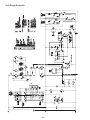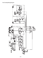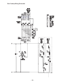
1
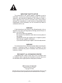
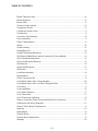
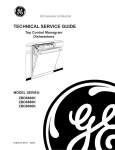
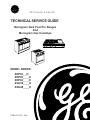
GE Consumer & Industrial
TECHNICAL SERVICE GUIDE
Monogram Dual Fuel Pro Ranges
And
Monogram Gas Cooktops
MODEL SERIES:
ZDP30_ _H
ZDP36_ _ _H
ZDP48_ _ _H
ZGU36_ _ _H
ZGU48_ _ _H
PUB # 31-9119 3/04
IMPORTANT SAFETY NOTICE
The information in this service guide is intended for use by
individuals possessing adequate backgrounds of electrical,
electronic, and mechanical experience. Any attempt to repair a
major appliance may result in personal injury and property
damage. The manufacturer or seller cannot be responsible for the
interpretation of this information, nor can it assume any liability in
connection with its use.
WARNING
If the information in this manual is not followed exactly, a fire or
explosion may result causing property damage, personal injury or
death. If you smell gas:
- Do not try to light any appliance.
- Do not touch any electrical switch; do not use any phone in
the building.
- Immediately call the gas supplier from a neighbor’s phone.
Follow the gas supplier’s instructions.
- If you cannot reach the gas supplier, call the fire department.
WARNING
To avoid personal injury, disconnect power before servicing this
product. If electrical power is required for diagnosis or test
purposes, disconnect the power immediately after performing the
necessary checks.
RECONNECT ALL GROUNDING DEVICES
If grounding wires, screws, straps, clips, nuts, or washers used
to complete a path to ground are removed for service, they must
be returned to their original position and properly fastened.
GE Consumer & Industrial
Technical Service Guide
Copyright © 2004
All rights reserved. This service guide may not be reproduced in whole or in part
in any form without written permission from the General Electric Company.
–2–
TABLE OF CONTENTS
Blower Thermal Cutout .................................................................................................... 16
Burner Alignment ............................................................................................................. 12
Burner Valve ..................................................................................................................... 11
Check for Proper Ignition ................................................................................................. 12
Component Access ........................................................................................................... 8
Component Locator Views ................................................................................................ 6
Components ...................................................................................................................... 8
Convection Fan Assembly ............................................................................................... 18
Door Assemblies ............................................................................................................... 9
Flame Characteristics ..................................................................................................... 11
Grates .............................................................................................................................. 12
Griddle Leveling ............................................................................................................... 15
Griddle Removal .............................................................................................................. 14
Griddle Thermostat Adjustment ....................................................................................... 15
Grill Burner/Griddle Burner Ignition Systems (On Some Models) .................................... 13
Grill or Griddle Air Adjustment .......................................................................................... 15
Grill or Griddle Igniter Removal ........................................................................................ 16
Grill Removal ................................................................................................................... 14
Ignition and Re-ignition ..................................................................................................... 12
Introduction ........................................................................................................................ 4
Lock Motor Assembly ....................................................................................................... 19
Nomenclature .................................................................................................................... 5
Orifice Conversion Kits .................................................................................................... 11
Oven Blower Motor (30-in. Range Models) ...................................................................... 20
Oven Blower Motor (36-in. and 48-in. Range Models) ..................................................... 19
Oven Door ......................................................................................................................... 8
Oven Light Bulbs ............................................................................................................. 10
Oven Select Switches ..................................................................................................... 17
Oven Thermostat ............................................................................................................. 17
Oven Thermostat Calibration ........................................................................................... 16
Relays, Convection Pulser Timers and Main Power Connection ..................................... 17
Schematics and Wiring Diagrams ................................................................................... 21
Simmer Orifice Burner Replacement .............................................................................. 11
Sparking ........................................................................................................................... 12
Spark Module ................................................................................................................... 13
Surface Burner ................................................................................................................ 10
Surface Burner Adjustments ............................................................................................ 11
Warranty .......................................................................................................................... 30
–3–
Introduction
The Monogram Ranges are available in 30-in.
36-in. and 48-in. configurations. The 36-in. can
have 6 burners, no grill or griddle or 4 burners
with grill or griddle. The 30-in. and 36-in. models
have a 27-in. self-cleaning oven and the 48-in.
model has an additional 12-in. standard clean
oven.
The gas cooktop-only models are available in
36-in. and 48-in. configurations with the same
grill and griddle combinations as the cooktop on
the 36-in. and 48-in. range models.
All models are available in either natural gas or
LP gas and must be ordered appropriately from
the dealer at the time of purchase.
36-in. Range Shown with Center Grill
48-in. Range Shown with Grill, Griddle, and 12-in. Oven
–4–
Nomenclature
Model Number
Z D P 4 8 N 4 G H 1 S S
Monogram
Stainless Steel
Eng. Digit
D = Dual Fuel
G = Gas
Model Year
G = Grill and Griddle
R = Grill Only
D = Griddle Only
P = Self Clean
U= Cooktop
4 = Surface Burners
6 = Surface Burners
Width
N = Natural Gas
L = LP Gas
Serial Number
The first two numbers of the serial number
identify the month and year of manufacture.
Example:
AG123456S = January, 2004
Mini-manual
The mini-manual is located behind the bottom
cover.
Nomenclature information is located on the
back of the range.
A - JAN
D - FEB
F - MAR
G - APR
H - MAY
L - JUN
M - JUL
R - AUG
S - SEP
T - OCT
V - NOV
Z - DEC
–5–
2005 - H
2004 - G
2003 - F
2002 - D
2001 - A
2000 - Z
1999 - V
1998 - T
1997 - S
1996 - R
1995 - M
1994 - L
The letter designating
the year repeats every
12 years.
Example:
T - 1974
T - 1986
T - 1998
Component Locator Views
36-in. Range Models
4
1
2
9
3
5
6
7
8
1 - Spark Module
6 - Relays
2 - Oven Select Switches
7 - Clean Timer
3 - Oven Control
8 - Terminal Block
4 - Door Lock High Limit
9 - Transformer
5 - Gas Shut-Off Valve
–6–
48-in. Range Models
4
2
1
2
3
9
5
6
7
8
1 - Spark Module
6 - Relays
2 - Oven Select Switches
7 - Clean Timer and Proof Timer
3 - Oven Control
8 - Terminal Block
4 - Door Lock High Limit
9 - Transformer
5 - Gas Shut-Off Valve
–7–
Components
Component Access
All 36-in. and 48-in. Models
1. Remove the manifold/valve panel:
30-in. Range Models
1. Remove the manifold/valve panel. (See 36-in.
and 48-in. Models.)
2. Remove the landing ledge:
a. Remove the knobs from the control
valves.
a. Remove the 4 Phillips head screws
holding the landing ledge in place, and lift
the ledge off.
b. Remove the 4 Torx screws located at
each corner of the manifold/valve panel.
c. Carefully pull off the panel. (Do not
scratch the panel.)
2. Remove the landing ledge:
a. Slide the right-side drip tray out (models
with a grill or griddle).
b. Remove the 4 Phillips head screws
holding the landing ledge in place, and lift
the ledge off.
48-in. Range Model Shown
Landing Ledge
Oven Door
To remove the door:
1. Fully open the door.
2. Each hinge has a hinge lock. Close the hinge
latches down against the door frame.
3. Firmly grasp the door at the top sides.
4. Close the door to the near-vertical position.
5. Lift the door up and pull straight out.
Hinge Lock
Pull the hinge locks
down to unlock.
–8–
To install the door:
Door Gasket
1. Firmly grasp the door at the top sides. This is
critical.
The gasket is attached to the front frame around
the outer edge of the oven liner. A series of spring
clips mounts the gasket to the front frame. The
ends are tucked into the front frame at the bottom
of the oven liner, leaving approximately 15 inches
of opening across the bottom for air intake on selfclean models. The gasket stops just above the
hinges on the standard oven.
2. Approach the range with the door angled in a
vertical position.
3. Guide the hinges into the slots.
4. Push the door in firmly while opening.
5. Once in position, open the door completely.
Push the hinge locks back in and toward the
front frame.
27-in. Oven
Note: If the door cannot be fully opened, the
hinge is not properly seated.
Window Gasket
Window Pack
Insulation
Door Liner
Insulation
Retainer
Compression
Brackets
Handle
End Cap
Door
Skin
Hinge
Handle
Door Assemblies
12-in. Oven (48-in. Range Models Only)
12-in. Oven Door (48-in. Range Model Only)
The oven door consists of outer and inner
assemblies. The outer assembly consists of the
outer panel and glass along with the handle and
spacers. The inner assembly consists of the
window pack, insulation guard, inner door panel
and hinges.
Door Liner
Window Gasket
Window Pack
Insulation
Insulation
Retainer
27-in. Oven Door (30-in., 36-in. and 48-in.
Range Models)
The oven door consists of an outer and inner
assembly. The outer assembly consists of an
outer panel and glass along with the handle and
spacers. The inner assembly is made up of the
window pack, insulation guard, inner door panel,
hinges and window pack gasket.
Door Hinge
–9–
Door
Skin
Handle
Oven Light Bulbs
Surface Burner
To remove the surface burner:
Socket
1. Lift off the burner cap and burner head.
Receptacle
2. Remove the burner ring locking nut using a
11/16-in. socket wrench, crescent wrench or
channel-lock pliers.
3. Lift off the burner ring. Do not remove the
burner base.
To replace the surface burner:
Bulb
1. Align the locator pins on the burner ring into
the labeled hole in the burnerbase. Seat in
place and push toward the electrode to set
gap properly.
Tab
Glass cover
Caution: Before replacing the oven light bulb,
disconnect the electrical power to the range at the
main fuse or circuit breaker panel.
2. Replace the burner ring locking nut. Tighten
the nut three times to remove small
imperfections in the parts. This will ensure the
nut remains tight over life:
•
•
Note: Allow light cover and bulb to cool
completely.
Hand tighten nut, tighten 1/4 turn with
wrench or pliers, then loosen.
Hand tighten nut a second time, tighten
/4 turn with wrench or pliers, then loosen.
1
•
Replace with a new 130V halogen bulb, not to
exceed 35 watts.
Hand tighten nut and final tighten 1/4 turn
with wrench or pliers.
3. Align the locator pin in the burner head into the
hole in the burner ring. Seat in place.
To remove and replace the oven light bulb:
1. Turn the glass cover counterclockwise 1/4 turn
until the tabs of the glass cover clear the
grooves of the socket.
4. Replace the burner caps.
Burner Cap
Burner Head
(Brass)
2. Using gloves or a dry cloth, remove the bulb
by pulling it straight out.
Locator Pins
3. Using gloves or a dry cloth, remove the new
bulb from its packaging. Do not touch the
bulb with bare fingers.
Burner Ring
(Aluminum)
Burner Ring
Locking Nut
With Chamfer
Side View
Locator Pin
4. Push the bulb straight into the receptacle all
the way. Place the tabs of the glass cover into
the grooves of the socket. Turn the glass
cover clockwise 1/4 turn to engage.
Pin Slot
Electrode
Burner Base
5. For improved lighting inside the oven, clean
the glass cover frequently using a wet cloth.
This should be done when the oven is
completely cool.
Note: Locator Pin Fits
Into Burner Base Pin Slot
6. Reconnect electrical power to the oven.
– 10 –
Flame Characteristics
Burner Valve
The burner valves are attached to the manifold by
two screws and contains an orifice which sets
the flow rate for the simmer flame. This valve
does not have a low flame adjustment, it is
controlled by the orifice size.
Burner flames should be blue and stable with no
yellow tips. (Yellow tipping may be normal for LP
gas.) The flame should not have excessive noise
or lifting of the flame from the burner. If any of
these conditions exist, check the burner ports for
blockage.
Simmer Orifice Burner Replacement
The simmer burner orifice requires a 4mm socket
to remove it. If necessary a 4mm socket is
available under part # WX05x10006.
Main Flame
Simmer Flame
Orifice Conversion Kits
Burner orifice conversion kits are available for:
•
Converting burner orifices from LP to Natural
Gas and from Natural Gas to LP
•
Installation at high altitudes
Natural/LP Conversion Kit - Order part number
WB49X10132
Surface Burner Adjustments
LP/Natural Conversion Kit - Order part number
WB49X10133
Standard adjustments to the air shutter and gas
metering orifices are not possible on sealed
burners.
High Altitude Conversion Kit – Order part number
WB49X10130
ORIFICE/JET SIZES
ORIFICE (mm)
RATE (BTU/HR)
SIMMER ORIFICE CODE
ORIFICE/JET SIZES
MAIN ORIFICE CODE
If burner flames appear to be abnormal, check the
following:
• Check gas pressure available to the burners.
The required operating pressure is 5" W.C.P.
Natural Gas or 10" W.C.P. L.P. (Propane) Gas.
• Check for drafts entering the burner box from
behind the cooktop.
• Check for blockage or partial blockage of the
orifice. Inspect the orifice to be sure it has
been drilled on center and is free of debris or
burrs.
• Check the burner alignment per Burner
Alignment.
• If the cause of the problem cannot be found,
installing an orifice with smaller diameter
openings may solve the problem. In high
altitude (above 6000 ft.) installation, the
orifices will usually have to be downsized.
BURNER
GAS
MAIN SIMMER Valve
HI
LO
SIM
D BURNER
D BURNER
GRILL/GRIDDLE
GRILL/GRIDDLE
NG
LP
NG
LP
1.85
1.18
1.93
1.32
17k
15k
18k
18k
2700
2500
6000
6000
1300 185 P
1200 118 E
–––– 48 –––
–––– 55 –––
0.57 mm
0.34 mm
–––––
–––––
0.57
0.34
0.94
0.47
HIGH ALTITUDE CONVERSION
Recommended Orifice Size for High Altitude Installation
Sea Level 3000 ft. 6000 ft.
BURNER
GAS
D BURNER
D BURNER
GRILL/GRIDDLE
GRILL/GRIDDLE
NG
LP
NG
LP
– 11 –
MAIN Orifice (mm)
1.85
1.18
1.93
1.32
1.78
1.09
1.85
1.32
1.61
1.07
1.70
1.18
Grates
Ignition and Re-ignition
To repair damaged feet on range cooktop grates,
order the repair kit, part # WB2X11095.
The ignition systems consists of 3 major
components.
• Transformer
• Spark Module
• Electrodes and Associated Wiring
Burner Alignment
Burner alignment is very important for proper
operation. Make sure the locator pin on the burner
ring is properly aligned with the hole on the burner
base. Each brass burner head is marked with a
clock face. Replace the burner head with the
arrow pointing to the rear of the cooktop (12
o’clock position).
Features of the cooktop determine whether the
ignition system uses a 4 or 5 wire spark module.
The spark modules are rated at 240v and have an
internal transformer. The internal transformer
serves two functions.
• An isolation device to prevent random
sparking in reverse polarity situations.
• To increase the input voltage from 120v to
240v.
During the ignition process all the electrodes will
spark simultaneously when any burner is
selected. Once the ignition process is complete,
the flame ionizes the surrounding air which
completes the sensing circuit and satisfies the
module that a flame is present.
Sparking
Check For Proper Ignition
All the igniters make clicking sounds and spark
even when only a single burner is being turned
on. Do not touch any of the burners when the
igniters are clicking.
1. Push in one control knob and turn 90° to LITE
position.
•
Input voltage should be 240 VAC and the
ground line should be properly connected to
the range chassis. Voltage should be
measured on one leg of the power supply.
•
Make sure electrical circuit is properly
polarized.
•
If the igniter electrodes continue to spark after
the burners are lit, check that each burner
component is assembled and seated properly
by observing uniform gaps between each
layer. Disassemble and reassemble as
required.
•
If water spills onto the electrode, the burner
will not reignite. The wet electrode will conduct
spark energy to ground, preventing it from
sparking or sensing flame across the spark
gap. The burner will operate normally once the
electrode and wiring connections are dry.
2. The igniter will spark and the burner will light;
the igniter will cease sparking when the
burner is lit.
3. The first test may require some time while air
is flushed out of the gas line.
4. Turn knob to OFF.
5. Repeat the procedure for each burner.
– 12 –
Grill Burner/Griddle Burner Ignition
Systems (On Some Models)
Spark Module
All 36-in. and 48-in. models have a single spark
module located behind the manifold/valve panel.
To remove the module:
1. Remove the manifold/valve panel (see
Component Access).
2. Remove the screws at the upper-right and
lower-left corners of the module.
3. Pull the module up and out.
36-in. Model Shown
The grill burner and griddle burner are ignited by
Norton style glowbar ignition systems. The ignition
circuit consists of the grill switch (grill burner
only), griddle thermostat (griddle burner only), the
igniter and the thermal/safety valve (gas valve).
The components are wired in series for each
cooking function.
Note: The igniter resistance decreases as the
igniter surface temperature increases. The safety
valve operates by current, not by voltage.
From a cold start, the igniter needs 30–60
seconds, with voltage applied, to reduce its
electrical resistance enough to provide a
minimum of 3.2 - 3.6 amps of current flow in the
series circuit. This is the required current flow
needed for the safety valve to open and supply
gas to the burner.
The glowbar should provide a steady current flow
of 3.2 to 3.6 amps flowing in the circuit. At that
point, the igniter temperature is between 1800°F
and 2500°F. The igniter will remain energized at all
times during burner operation. If the igniter glows
red but does not draw at least 3.2 - 3.6 amps, the
fault is usually with the igniter, not the valve.
30-in. Range Models
30-in. range models have a single spark module
located in the center of the burner box.
Spark Module
To remove the module:
1. Remove the burner grates.
2. Lift off the center trim from the burner
maintop.
3. Remove the 2 screws at the front and rear of
the air duct cover, and remove the cover.
4. Remove the 2 screws securing the spark
module to the range.
– 13 –
Grill Removal
Griddle Removal
To remove the grill burner assembly:
To remove the griddle assembly:
1. Remove the grill cover, grill grates and grill
radiant.
1. Remove the griddle cover.
2. Lift off the front trim from the front of the grill.
2. Lift off the front trim from the front of the
griddle.
3. Remove the 2 Phillips head screws at the
front of the grill box that secure the grill box to
the cooktop.
3. Remove the 2 Phillips head screws at the
front of the griddle that secure the griddle to
the cooktop.
4. Carefully lift up the grill box enough to access
the wire nut connecting the igniter to the
neutral, and unscrew the nut. Unplug the wire
going to the valve.
4. Remove the rear cover from the rear of the
griddle.
5. Lift the grill up and off the cooktop.
5. Remove the center shipping screw and
washer, if they have not already been
removed.
Note: Do not remove the 2 outer leveling screws.
Grill Cover
6. Lift the griddle assembly out of the opening
and pull out the thermostat capillary from
beneath the plate.
Leveling
Screws
Grill Grates
Burner
Grill Radiant
Rear
Cover
Igniter
Griddle
Plate
Assembly
Griddle
Cover
Front
Trim
Igniter
Grill Box
Burner
Front
Trim
Griddle Baffle
– 14 –
Grill or Griddle Air Adjustment
Griddle Leveling
1. For the grill, remove the grill cover, grates and
grill radiant. For the griddle, remove the
griddle assembly (see Griddle Removal).
The 2 screws at the rear of the griddle plate
assembly are leveling screws. They can be
turned to level the griddle or to provide a forward
slope to help grease and oils to drain away from
the food being cooked.
2. If adjusting the grill air shutter, remove the 2
Phillips head screws at the rear of the burner
and lift the burner out.
3. Loosen the screw on the burner air shutter
using a flat head screwdriver.
Griddle Thermostat Adjustment
To adjust the griddle thermostat:
1. Pull the griddle control knob off.
2. On the back of the knob, loosen both screws,
but do not completely remove.
3. With the back of the knob facing you, hold the
outer edge of the knob with one hand and turn
the back of the knob with the other hand.
4. To raise the griddle temperature, turn the back
of the knob clockwise. To lower the griddle
temperature, turn the back of the knob
counterclockwise.
4. Using a flat head screwdriver, move the air
shutter in the appropriate direction. If the
flame is too yellow, indicating insufficient air,
adjust the shutter counterclockwise to
increase the airflow. If the flame is too low or
tends to lift away from the burner, indicating
too much air, turn the shutter clockwise to
reduce the airflow.
5. Test and adjust as needed for proper flame
characteristics.
5. After the adjustment is made, retighten
screws so they are snug, and replace knob.
Ð20û
Ð10û
GRIDDLE
HO
T/
Ð24û
LD +24û
CO
+12û Ð12û
OVEN
+20û
+10û
– 15 –
Oven Thermostat Calibration
Grill or Griddle Igniter Removal
1. For the grill, remove the grill cover, grates and
grill radiant. For the griddle, remove the
griddle assembly (see Griddle Removal).
2. Remove the 2 Phillips head screws at the
rear of the burner and lift the burner out.
The AVERAGE center oven temperature should
be 350° ±15°F for baking at the 350°F setting.
Customers may change the average center oven
temperature by ±24°F to satisfy their own
cooking needs.
To adjust the oven thermostat:
3. Remove the 2 flat head screws holding the
igniter to the support bracket on the burner.
1. Pull the oven control knob off.
4. Replace with new igniter and replace all parts.
Note: When aligned properly, the dimple on the
igniter bracket should fit into the notch on the
support bracket on the burner.
2. On the back of the knob, loosen both screws,
but do not completely remove.
3. With the back of the knob facing you, hold the
outer edge of the knob with one hand and turn
the back of the knob with the other hand.
4. To raise the oven temperature, turn the back
of the knob clockwise. To lower the oven
temperature, turn the back of the knob
counterclockwise.
Igniter
5. After the adjustment is made, retighten
screws so they are snug, and replace knob.
Ð20û
Ð10û
GRIDDLE
HO
T/
Ð24û
LD +24û
CO
+12û Ð12û
OVEN
+20û
+10û
Burner
GRILL OR GRIDDLE OHMMETER TEST
COMPONENT
IGNITER
VALVE
SWITCH
OHMS
45–400 OHMS COLD
1.0 to 1.2 OHMS
0 OHMS CLOSED
GRILL
L1
N
HEAT
LIGHT
Blower Thermal Cutout
GRILL
SWITCH
NC
C
VALVE
IGNITER
GRIDDLE
L1
N
The thermal cutout will turn on the blower in any
mode of operation when it detects a temperature
in the control area of approximately 210°F. The
blower will cycle off when temperatures cool
below 120°F.
HEAT
LIGHT
GRIDDLE
SWITCH
NO
C
THERMOSTAT
VALVE
IGNITER
– 16 –
Oven Select Switches
Relays, Convection Pulser Timers and
Main Power Connection
Select switch operation can be checked with
ohmmeter and strip circuits that show what
contacts are closed in each mode of operation.
Electrical relays and timers are located in the
compartment below the oven.
Remove the 2 screws from the top corners of the
bottom panel and pull straight off.
27-in. Oven
32 30 28 26 24 22 20 18 16 14 12 10
31 29 27
19 17
11
9
48-in. Range Models
Convection Broil
Unit Pulsar
K2 Relay
Clean Lockout Relay
Proof Timer
Clean Timer
K1 Relay
K4 Relay
K3 Relay
Terminal Block
12-in. Oven
61 59 57 55 53 51 49
58 56
47 45 43 41
48 46 46
42 40
30-in. and 36-in. Range Models
Convection Broil
Unit Pulsar
Terminal Block
Clean Timer
K3 Relay
K4 Relay
K1 Relay
Oven Thermostat
The operation of the thermostat contacts can be
checked with an ohmmeter and strip circuits.
Contacts 1 and 2 are the cycling contacts, which
are controlled by the expansion and contraction of
the helium in the capillary. Contacts 7 and 8 will
always be in the CLOSED position, except when
in the CLEAN mode of operation. (See above
illustration.)
– 17 –
Convection Fan Assembly
The convection fan assembly is located behind the large oven liner.
To remove the convection fan assembly:
1. Disconnect power and remove the oven door and racks.
2. Loosen the fan cover mounted by 4 screws and spacers. Lift the cover off the keyhole opening.
3. Remove the 4 screws securing the fan assembly to the mounting plate.
4. Carefully pull the fan assembly into the oven.
Note: Fan assembly is heavy.
5. Disconnect the wires to remove the assembly from the oven, and place the assembly on a flat
surface for repair.
36-in. and 48-in. Range Models
Convection Oven Cavity
Fan Cover Back
Spacer (4)
Convection
Fan Cover
Convection
Fan Assembly
Mounting
Screws (4)
5/32 Blade
Mounting Screw
(Allen)
Start/Run
Capacitor
Cover
Mounting
Screws (4)
Convection
Fan Blade
Wiring Compartment
Cover
Motor Cooling
Fan Blade
Convection
Fan Motor
Convection Fan Motor
Mounting Plate
Insulation
5/22 Blade Mounting
Screws (Allen) (2)
Convection Fan
Assembly Mounting Plate
30-in. Range Models
– 18 –
Lock Motor Assembly
LOCKING
L2
The lock motor assembly is located at the center
top of the oven front frame. The assembly
consists of the mounting plate, motor, micro
switches, cam and hook assembly.
L1
120V.
LATCH
"CLOSED"
SW
C
31
LOCK
LIGHT
K3
RELAY
SEL
SW
NC
32
9
6
NO
2
NC
8
K3 RELAY
COIL
K3
RELAY
8
NO
5
A
B
K3
RELAY
To access the assembly:
7
1. Open the oven door.
UNLOCKING
LM
4
NO
L2
L1
120V.
2. Remove the 2 Torx screws securing the
mounting plate to the front frame and pull the
assembly out.
K4 RELAY
COIL
A
LATCH
"OPEN"
SW
C
Door lock motor operation:
NC
K4
RELAY
9
1. When the oven controls are set for CLEAN,
power is applied to the K3 relay coil, which
will energize the lock motor.
2. The lock motor drives the cam that closes
the latch CLOSED switch. As the lock hook
engages, the motor position switch will open,
supplying power to the K1 relay, which turns
the clean timer on.
3. At the end of the clean cycle, when the select
switch is pushed to off or another mode of
operation, the K4 relay will energize the lock
motor to drive the cam to the unlock position.
SEL
SW
29
B
K4
RELAY
T STAT
7
30
4
CLOSED
< 550˚F
6
NO
K3
RELAY
9
LOCK
LIGHT
3
NO
LM
Oven Blower Motor (36-in. and 48-in. Range
Models)
The blower motor assemblies are located on the
back of the range above each oven.
The air switch on the blower motor completes the
circuit to the oven thermostat.
Air Switch
Motor Position
Switch
Fan Assembly
Lock Motor
Mounting Plate
Screws (4)
Blower
Thermostat
Fan
Thermostat
Motor Mounting
Screws (2)
Fan Mounting
Plate
To remove the blower assembly:
Mounting
Plate
1. Remove the cooktop burner assemblies.
2. Remove the 4 screws securing the fan
mounting plate, and pull the plate with
attached blower motor forward.
3. Remove the blower motor from its mounting
plate by loosening the 2 screws on the plate
and sliding the blower to the right.
4. Install in reverse order.
– 19 –
Oven Blower Motor (30-in. Range Models )
The blower motor assembly is located on the
back of the range above the oven. The air switch
on the blower motor completes the circuit to the
oven thermostat and hot wire relay.
To remove the blower assembly:
Reignition
Module Screw
1. Lift off the burner cap.
2. Remove the left-side burner assembly and
disconnect the ignition wires.
7. On the spark module, cut the wire tie securing
the module, and disconnect the spark module
from the wire harness by pulling straight off
the connector.
Spark Module
Connector
3. Remove the screws at the front and back of
the air duct cover to reveal the spark module.
(See Spark Module.)
8. Lift the air duct out (with the wires still
connected to the spark module), and set it
aside.
4. Lower the manifold/valve panel. (See
Component Access).
5. Locate the bracket holding the oven
thermostat in place. Remove the 2 screws
securing the bracket, and pull the thermostat
out of the way to reveal the re-ignition module
bracket.
9. Locate the blower motor cover at the center
rear of the burner box. Remove the 2 screws
securing the blower motor cover, and lift the
blower motor up and into the burner box.
6. Remove the screw from the re-ignition module
bracket.
Screw
Blower
Motor Cover
– 20 –
Screw
Schematics and Wiring Diagrams
WARNING: Disconnect electrical power before servicing.
Caution: Label all wires prior to disconnection. Wiring errors can cause improper and dangerous
operation. Verify operation after servicing.
Oven Circuits
BAKE 27-in Oven
L2
CONVECTION BAKE
L2
L1
L1
240V.
11
11
ON
LIGHT
SEL
SW
19
FAN
T STAT
20
T STAT
T STAT
8
2
7
ON
LIGHT
HEAT
LIGHT
BAKE
UNIT
12.92A
1
4.17A
3100W
BROIL
BROIL
UNIT 1 UNIT 2
2000W
HIGH
TEMP
CUTOUT
SEL
SW
12.92A
10
19
9
16
T STAT
8
2
7
1
3100W
BROIL
BROIL
UNIT 1 UNIT 2
2000W
L1
10
9
50%
4.17A PULSER
SEL
SW
14
2000W
9
• The Convection Fan will turn on as soon as the CONV switch is pressed and
will remain on until the OFF switch is pressed or another mode of operation is
selected.
• Throughout the convection mode, anytime the bake unit cycles on, the broil unit
will be cycled at approximately a 50% rate at 120 volts.
N
CLEAN
L2
ON
LIGHT
HEAT
LIGHT
K1 RELAY
7
FAN
T STAT
1
SEL
SW
50
SEL
SW
51
48
T STAT
49
8
T STAT
7
L1
240V.
42
BAKE
UNIT
11.67A
SEL
SW
11.67A
41 40
2800W
BROIL
BROIL
SEL
UNIT 1 UNIT 2
SW
3.75A
3.75A
41 40
1800W 1800W
HIGH
TEMP
CUTOUT
LATCH
"CLOSED"
SW
C
N
BM
4
NO 27
CLEAN
TIMER
K1 RELAY
COIL
SEL
SW
28
A
B
1
N
2
HEAT
LIGHT
ON
LIGHT
BROIL 27-in Oven
L2
SEL
SW
L1
19
FAN
T STAT K1 RELAY
22
6
T STAT
2
9
19
26
N
BM
1
8
2
11
ON
LIGHT
SEL
SW
FAN
T STAT
SEL
SW
8
22
T STAT
7
2
L2
BROIL
UNIT 1
8.3A
1
8.3A
12
2000W
SEL
SW
17
8.3A
18
BROIL
UNIT 2
HIGH
TEMP
CUTOUT
SEL
SW
17
18
8.3A
12
BROIL
UNIT 2
9
8.3A
2000W
12-in. Oven Only
PROOF
HEAT
LIGHT
SEL
SW
HIGH
TEMP
CUTOUT
SEL
SW
8.3A
2000W
WILL NOT
OPERATE
WHEN SELECT
BUTTON IS SET
FOR CLEAN
GRILL
GRIDDLE
12" OVEN
OVEN LIGHT
K1 RELAY
BROIL
UNIT 1
8.3A
240V.
SEL
SW
19
HIGH
TEMP
CUTOUT
SEL
SW
12.92A
240V.
B
3
BAKE
UNIT
12.92A
9
BAKE 12-in. Oven
K5 RELAY
COIL
A
20
T STAT
4.17A
• During bake operation the broil unit is on 1/4 wattage while bake unit is
energized.
L2
FAN
T STAT
SEL
SW
4.17A
2000W
SEL
SW
HEAT
LIGHT
L1
240V.
58
K5 RELAY
COIL
8.3A
2000W
A
B
CLEAN
TIMER
K2 RELAY
COIL
SEL
SW
9
59
A
1
B
N
2
N
42
ON
LIGHT
HEAT
LIGHT
BROIL 12-in. Oven
L2
L1
FAN
T STAT
240V.
SEL
SW
56
57
3
N
BM
K5 RELAY
COIL
A
N
B
42
ON
LIGHT
FAN
T STAT
3
1
SEL
SW
50
53
SEL
SW
48
49
HEAT
LIGHT
T STAT
T STAT
8
2
7
BROIL
UNIT 1
7.5A
SEL
SW
46
47
7.5A
43
BROIL
UNIT 2
HIGH
TEMP
CUTOUT
SEL
SW
7.5A
1800W
1
40
7.5A
1800W
– 21 –
1
SEL
SW
50
55
7
NO
BROIL
UNIT 1
4
1800W
3.75A
BROIL
UNIT 2
1800W
3.75A
HIGH
TEMP
CUTOUT
SEL
SW
45
40
36-in. Range Wiring Diagram
– 22 –
36-in Range Schematic
– 23 –
48-in. Range Wiring Diagram
– 24 –
48-in Range Schematic
– 25 –
30-in Range Schematic
– 26 –
30-in. Range Wiring Diagram
– 27 –
Gas Cooktop Wiring Diagram
– 28 –
Gas Cooktop Wiring Schematic
– 29 –
Warranty
MONOGRAM RANGE WARRANTY
Proof of original purchase date is needed to obtain service under warranty.
WHAT IS
COVERED
FULL ONE-YEAR WARRANTY
For one year from date of original purchase, we
will provide, free of charge, parts and service
labor in your home to repair or replace any part
of the range that fails because of a
manufacturing defect.
LIMITED FIVE-YEAR WARRANTY
For five years from the date of original purchase,
we will provide, free of charge, replacement gas
surface burners if they fail in normal household
use. (The grill, griddle and oven burners are not
included.) You pay for the service trip to your
home and all service labor charges.
WHAT IS
NOT
COVERED
This warranty is extended to the original
purchaser and any succeeding owner for products
purchased for ordinary home use in the 48
mainland states, Hawaii and Washington, D.C. In
Alaska the warranty is the same except that it is
LIMITED because you must pay to ship the
product to the service shop or for the service
technician’s travel costs to your home.
All warranty service will be provided by our
Factory Service Centers or by our authorized
Customer Care® servicers during normal working
hours.
Should your appliance need service, during
warranty period or beyond, in the U.S.A. call
800.444.1845. In Canada: 888.880.3030.
•
Service trips to your home to teach you how
to use the product.
•
Damage to the product caused by accident,
fire, floods or acts of God.
•
Discoloration of the griddle plate.
•
•
Chipping of porcelain enamel grates.
Failure of the product if it is used for other
than its intended purpose or used
commercially.
•
Replacement of house fuses or resetting of
circuit breakers.
•
•
Incidental or consequential damage caused
by possible defects with this appliance.
•
Damage after delivery.
Improper installation, delivery or maintenance.
If you have an installation problem, contact
your dealer or installer. You are responsible
for providing adequate electrical, gas,
exhausting and other connecting facilities as
described in the Installation Instructions
provided with the product.
Some states do not allow the exclusion or limitation of incidental or consequential damages, so the
above limitation or exclusion may not apply to you. This warranty gives you specific legal rights, and
you may also have other rights which vary from state to state. To know what your legal rights are in
your state, consult your local or state consumer affairs office or your state’s Attorney General.
Warrantor: General Electric Company. If further help is needed concerning
Natural Gas Models
ZDP48N4G
ZDP48N6R
ZDP48N6D
ZDP36N6
ZDP36N4R
ZDP36N4D
ZDP30N4
Liquid Propane Models
ZDP48L4G
ZDP48L6R
ZDP48L6D
ZDP36L6
ZDP36L4R
ZDP36L4
DZDP30L4
– 30 –