1
External Bus Cycles
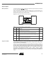
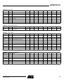
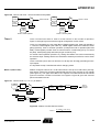
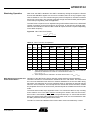
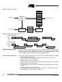
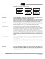
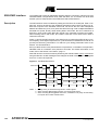
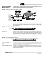
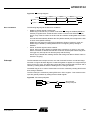
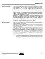
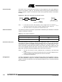
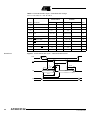
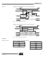
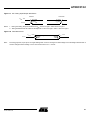
This section describes the bus cycles that AT89C5132 executes to read (see
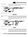
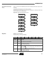
Figure 16), and write data (see Figure 17) in the external data memory.
External memory cycle takes 6 CPU clock periods. This is equivalent to 12 oscillator
clock periods in standard mode or 6 oscillator clock periods in X2 mode. For further
information on X2 mode, refer to the section “X2 Feature”, page 11.
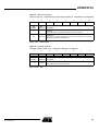
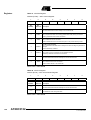
Slow peripherals can be accessed by stretching the read and write cycles. This is done
using the M0 bit in AUXR register. Setting this bit changes the width of the RD and WR
signals from 3 to 15 CPU clock periods.
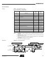
For simplicity, the accompanying figures depict the bus cycle waveforms in idealized
form and do not provide precise timing information. For bus cycle timing parameters
refer to the section “AC Characteristics”.
Figure 16. External Data Read Waveforms
CPU Clock
ALE
RD(1)
P0
P2
Notes:
DPL or Ri
D7:0
DPH or P2(2),(3)
P2
1. RD signal may be stretched using M0 bit in AUXR register.
2. When executing MOVX @Ri instruction, P2 outputs SFR content.
3. When executing MOVX @DPTR instruction, if DPHDIS is set (Page Access Mode),
P2 outputs SFR content instead of DPH.
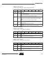
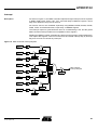
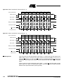
Figure 17. External Data Write Waveforms
CPU Clock
ALE
WR(1)
P0
P2
Notes:
24
DPL or Ri
P2
D7:0
DPH or P2(2),(3)
1. WR signal may be stretched using M0 bit in AUXR register.
2. When executing MOVX @Ri instruction, P2 outputs SFR content.
3. When executing MOVX @DPTR instruction, if DPHDIS is set (Page Access Mode),
P2 outputs SFR content instead of DPH.
AT89C5132
4173C–USB–07/04