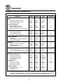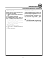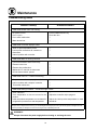
1
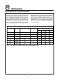
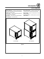
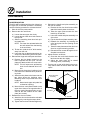
KCOĆ25E
CONVECTION OVEN
INSTALLATION - OPERATION - MAINTENANCE
BLODGETT OVEN COMPANY
www.blodgett.com
44 Lakeside Avenue, Burlington, Vermont 05401 USA Telephone: (802) 658Ć6600 Fax: (802)864Ć0183
PN 32219 Rev E (12/04)
E 2000 - G.S. Blodgett Corporation
IMPORTANT
WARNING: IMPROPER INSTALLATION, ADJUSTMENT,
ALTERATION, SERVICE OR MAINTENANCE CAN CAUSE
PROPERTY DAMAGE, INJURY OR DEATH. READ THE INĆ
STALLATION, OPERATING AND MAINTENANCE INĆ
STRUCTIONS THOROUGHLY BEFORE INSTALLING OR
SERVICING THIS EQUIPMENT
FOR YOUR SAFETY
Do not store or use gasoline or other flammable vapors or
liquids in the vicinity of this or any other appliance.
The information contained in this manual is important for the proper
installation, use, and maintenance of this oven. Adherence to these
procedures and instructions will result in satisfactory baking results
and long, trouble free service. Please read this manual carefully and
retain it for future reference.
Errors: Descriptive, typographic or pictorial errors are subject to correcĆ
tion. Specifications are subject to change without notice.
THE REPUTATION YOU CAN COUNT ON
For over a century and a half, The Blodgett Oven Company has been building
ovens and nothing but ovens. We've set the industry's quality standard for all
kinds of ovens for every foodservice operation regardless of size, application
or budget. In fact, no one offers more models, sizes, and oven applications
than Blodgett; gas and electric, fullĆsize, halfĆsize, countertop and deck, conĆ
vection, Cook'n Hold, CombiĆOvens and the industry's highest quality Pizza
Oven line. For more information on the full line of Blodgett ovens contact your
Blodgett representative.
Model:
Your Service Agency's Address:
Serial Number:
Your oven was installed by:
Your oven's installation was checked by:
Table of Contents
Introduction
Oven Description and Specifications . . . . . . . . . . . . . . . . . . . . . . . . . . . . . . . .
Oven Components . . . . . . . . . . . . . . . . . . . . . . . . . . . . . . . . . . . . . . . . . . . . . . .
2
3
Installation
Delivery and Location . . . . . . . . . . . . . . . . . . . . . . . . . . . . . . . . . . . . . . . . . . . . .
Oven Assembly . . . . . . . . . . . . . . . . . . . . . . . . . . . . . . . . . . . . . . . . . . . . . . . . . .
Leg Attachment . . . . . . . . . . . . . . . . . . . . . . . . . . . . . . . . . . . . . . . . . . . . . . .
Oven Leveling . . . . . . . . . . . . . . . . . . . . . . . . . . . . . . . . . . . . . . . . . . . . . . . .
Double Stacking . . . . . . . . . . . . . . . . . . . . . . . . . . . . . . . . . . . . . . . . . . . . . .
Door Relocation . . . . . . . . . . . . . . . . . . . . . . . . . . . . . . . . . . . . . . . . . . . . . . .
Utility Connections . . . . . . . . . . . . . . . . . . . . . . . . . . . . . . . . . . . . . . . . . . . . . . .
4
5
5
5
5
6
7
Operation
Safety Information and Operating Tips . . . . . . . . . . . . . . . . . . . . . . . . . . . . . .
Solid State Digital Control . . . . . . . . . . . . . . . . . . . . . . . . . . . . . . . . . . . . . . . . .
Suggested Times and Temperatures . . . . . . . . . . . . . . . . . . . . . . . . . . . . . . . .
8
9
12
Maintenance
Cleaning and Preventative Maintenance . . . . . . . . . . . . . . . . . . . . . . . . . . . . .
Troubleshooting Guide . . . . . . . . . . . . . . . . . . . . . . . . . . . . . . . . . . . . . . . . . . . .
13
14
Introduction
Oven Description and Specifications
Cooking in a convection oven differs from cooking
in a conventional deck or range oven since heated
air is constantly recirculated over the product by
a fan in an enclosed chamber. The moving air conĆ
tinually strips away the layer of cool air surroundĆ
ing the product, quickly allowing the heat to peneĆ
trate. The result is a high quality product, cooked
at a lower temperature in a shorter amount of time.
Blodgett convection ovens represent the latest adĆ
vancement in energy efficiency, reliability, and
ease of operation. Heat normally lost, is recircuĆ
lated within the cooking chamber before being
vented from the oven: resulting in substantial reĆ
ductions in energy consumption and enhanced
oven performance.
ELECTRICAL SPECIFICATIONS (per section)
KW
Hz
Volts
Amps
Phase
L1
L2
L3
N
3.0
60
208
1
15
15
-
-
3.0
60/50
240
1
13
13
-
-
3.0
60/50
220
1
14
-
-
14
3.0
60/50
230
1
13
13
-
-
3.0
60/50
200
1
15
-
-
15
3.0
60/50
240
1
13
-
-
13
NOTE: Load ratings are double the above data for double stacked units.
2
Introduction
Oven Components
Heating Elements - located on the back wall of
the oven, the elements provide heat to the baking
chamber on electric ovens.
Blower Wheel Cover - located on the back interiĆ
or wall of the oven. Protects the blower wheel.
Blower Wheel - spins to circulate hot air in the
baking chamber.
Control Panel - contains wiring and components
to control the oven operation.
Convection Motor - provides power to turn the
blower wheel.
Oven Racks - three racks are provided standard.
Rack Supports - hold oven racks.
KCO-25E Single
KCO-25E Double
Figure 1
3
Installation
Delivery and Location
DELIVERY AND INSPECTION
OVEN LOCATION
All Blodgett ovens are shipped in containers to
prevent damage. Upon delivery of your new oven:
The well planned and proper placement of your
oven will result in long term operator convenience
and satisfactory performance.
D
D
Inspect the shipping container for external damĆ
age. Any evidence of damage should be noted
on the delivery receipt which must be signed by
the driver.
Uncrate the oven and check for internal damĆ
age. Carriers will accept claims for concealed
damage if notified within fifteen days of delivery
and the shipping container is retained for inĆ
spection.
D
D
The Blodgett Oven Company cannot assume
responsibility for loss or damage suffered in
transit. The carrier assumed full responsibility
for delivery in good order when the shipment
was accepted. We are, however, prepared to
assist you if filing a claim is necessary.
Place the oven in an area which is accessible for
proper operation and servicing.
It is also essential that ventilation air not be obĆ
structed in any way if proper operation is to be
assured. Tripping of the blower motor thermal
overload protective device is caused by excesĆ
sive ambient temperature in the motor compartĆ
ment resulting from insufficient ventilation.
Such a condition must be corrected immediateĆ
ly if permanent damage to the oven is to be
avoided.
Before making any utility connections to this oven,
check the rating plate attached to the back of the
oven to be sure the oven specifications are comĆ
patible with the electrical services supplied for the
oven.
4
Installation
Oven Assembly
DOUBLE STACKING
1. Mount the lower section on legs as directed.
2. Set the upper section on the lower section.
3. Remove the two stacking straps from the botĆ
tom unit.
4. Remove the bottom left and right screws from
the upper section.
5. ReĆattach the two stacking straps with the
screws removed in Steps 3 and 4.
LEG ATTACHMENT
NOTE: Before operating the KCOĆ25E, the unit
must be mounted on the legs provided.
1. Tilt the oven onto its back.
2. Screw 4" legs into four holes located near
oven corners.
3. Use a tool to tighten the hex nut at the top of
each leg.
4. Lift oven forward onto legs.
Figure 2
OVEN LEVELING
After the oven is mounted on the legs it should be
leveled by screwing the adjustable leg feet in or
out as necessary. Check with a spirit level placed
on the top of the oven.
Stacking
Straps
Figure 3
5
Installation
Oven Assembly
DOOR RELOCATION
The KCOĆ25E is shipped with the door hinged on
the right side. If left hand operation is necessary
use the following procedure to relocate the door.
5. Relocate the handle and plate assembly on
the door as follows:
a.) Remove the four hex head screws which
attach the handle plates to the door.
b.) Twist the upper plate around the door
handle by at least 90_.
c.) Lower the handle and plate assembly out
of the door.
d.) Flip the handle and plate assembly 180_.
e.) Reattach the assembly by inserting the
roller latch plate into the opening at the
door top.
f.) Twist the lower plate around the door hanĆ
dle to its original mounting position.
g.) Reinstall the four screws through the hanĆ
dle plate into the door.
6. Adjust the door as follows:
a.) Close the door and check that the roller
latch secures the door tightly.
b.) Adjust the catch plate (by its slotted
mounting holes) if necessary.
7. Turn the unit on and verify that the door proxĆ
imity switch shuts off the fan when the door
opens.
1. Shut off the oven power switch.
2. Remove the door as follows:
a.) Loosen the two upper door bolts.
b.) Loosen the two lower door bolts. Remove
the top bolt.
c.) Slide the remaining lower door bolt up in
its slotted hole.
NOTE: The lower door pin attached to the
bolt will release from the bushing
in the unit frame.
d.) Tilt the door (with the 5/16" thick washer)
away from the unit.
e.) Lower the door so that the upper door pin
drops out of the bushing in the unit frame.
3. Relocate the hinge and catch parts as follows:
a.) Remove the trim plates located on the
frame opposite the door pins. The two
plates are attached with one screw each.
NOTE: This will expose the pin/bushing
holes for the alternate door locaĆ
tion.
b.) Move the two brass door bushings in the
unit frame to the alternate door pin/bushĆ
ing holes.
c.) Attach the trim plates to the frame over the
two holes where the bushings were.
Mounting holes are provided at the new
locations.
NOTE: Note that the upper trim plate has
a slotted air opening.
d.) Move the door catch plate located on the
upper door frame to the opposite side of
the oven cavity. Mounting holes are proĆ
vided at the new location for the catch
plate (two screws).
4. Reattach the door as follows:
a.) Attach the door to the unit at the relocated
bushings by reversing the steps above.
b.) Tighten the four door bolts hand tight only.
Door Catch
Under Overhand
Handle & Plate
Assembly
Door Bolt
Trim Plate
Figure 4
6
Installation
Utility Connections
ELECTRICAL CONNECTION
THE INSTALLATION INSTRUCTIONS CONĆ
TAINED HEREIN ARE FOR THE USE OF QUALIĆ
FIED INSTALLATION AND SERVICE PERSONNEL
ONLY. INSTALLATION OR SERVICE BY OTHER
THAN QUALIFIED PERSONNEL MAY RESULT IN
DAMAGE TO THE OVEN AND/OR INJURY TO
THE OPERATOR.
U.S and Canadian installations
This unit is supplied with a power cord and 6Ć20P
NEMA plug (3 prong grounding 250 volt). It is inĆ
tended for use with a 6Ć20R NEMA receptacle.
Qualified installation personnel are individuals, a
firm, a corporation, or a company which either in
person or through a representative are engaged
in, and responsible for:
D
WARNING!!
This appliance is equipped with three
prong grounding type plug for your
protection against shock hazard and
should be plugged directly into a properly
grounded three prong receptacle. DO
NOT cut or remove the grounding prong
from this plug.
the installation of electrical wiring from the elecĆ
tric meter, main control box or service outlet to
the electric appliance.
Qualified installation personnel must be experiĆ
enced in such work, familiar with all precautions
required, and have complied with all requirements
of state or local authorities having jurisdiction.
General export installations
Before making any utility connections to this oven,
check the rating plate attached to the back of the
oven to be sure the voltage, phase and KW rating
are compatible with the electrical services supĆ
plied for the oven. See the table on page 2 for elecĆ
trical specifications.
U.S. and Canadian installations
All ovens, when installed, must be electrically
grounded in accordance with local codes, or in the
absence of local codes, with the National Electrical
Code, ANSI/NFPA 70-Latest Edition and/or CanaĆ
dian National Electric Code C22.2 as applicable.
THE BLODGETT OVEN COMPANY CANNOT ASĆ
SUME RESPONSIBILITY FOR LOSS OR DAMAGE
SUFFERED AS A RESULT OF IMPROPER INSTALĆ
LATION.
The ventilation of this oven should be in accorĆ
dance with local codes. In the absence of local
codes, refer to the National ventilation code titled,
Standard for the Installation of Equipment for the
Removal of Smoke and Grease Laden Vapors from
Commercial Cooking Equipment", NFPAĆ96ĆLatest
Edition.
General export installations
Installation must conform with Local and National
installation standards. Local installation codes
and/or requirements may vary. If you have any
questions regarding the proper installation and/or
operation of your Blodgett oven, please contact
your local distributor. If you do not have a local disĆ
tributor, please call the Blodgett Oven Company at
0011Ć802Ć860Ć3700.
7
Operation
Safety Information and Operating Tips
THE INFORMATION CONTAINED IN THIS SECĆ
TION IS PROVIDED FOR THE USE OF QUALIFIED
OPERATING PERSONNEL. QUALIFIED OPERATĆ
ING PERSONNEL ARE THOSE WHO HAVE
CAREFULLY READ THE INFORMATION CONĆ
TAINED IN THIS MANUAL, ARE FAMILIAR WITH
THE FUNCTIONS OF THE OVEN AND/OR HAVE
HAD PREVIOUS EXPERIENCE WITH THE OPĆ
ERATION OF THE EQUIPMENT DESCRIBED. ADĆ
HERENCE TO THE PROCEDURES RECOMĆ
MENDED
HEREIN WILL ASSURE THE
ACHIEVEMENT OF OPTIMUM PERFORMANCE
AND LONG, TROUBLEĆFREE SERVICE.
OPERATING TIPS
Please take the time to read the following safety
and operating instructions. They are the key to the
successful operation of your Blodgett conveyor
oven.
Never place a pan or aluminum foil on the bottom
of the oven. This obstructs the flow of air and reĆ
sults in uneven baking and roasting.
Oven Temperature
Follow the Time and Temperature recommendaĆ
tions provided for the product to be prepared in
the oven. Cooking at higher temperatures will not
reduce cooking time, it will produce unsatisfactory
results.
Pans and Racks
Product or pan height determines how many
racks are used. The oven holds up to three 9" x 13"
racks.
Baking
Weigh the product to ensure equal distribution in
each pan. Varying amounts of product will cause
uneven baking results.
SAFETY TIPS
For your safety read before operating
D
DO NOT remove the control panel cover unless
the oven is unplugged.
8
Operation
Solid State Digital Control
OVEN CONTROLS
Indicates the oven temperature is too low
for the selected product recipe. Wait until
is displayed.
1. POWER ON/OFF Ć controls the operation of
the oven. When lit the power to the unit is on.
If the switch is not lit, the power to the unit is
off.
2. DISPLAY - displays time, temperature and
other information related to oven function.
Time is displayed in minutes and seconds and
counts down.
3. START/STOP KEY - starts or stops the seĆ
lected product key program.
4. PRODUCT KEYS (1Ć6) - associates a time
and temperature with a specific product for
each key.
5. PROGRAM KEY - accesses the program
mode to set or change the time or temperature
of a product key.
6. HEAT LIGHT - indicates that the elements are
operating.
Indicates the oven has reached the seĆ
lected recipe temperature. Ready for prodĆ
uct load.
Indicates the number of pans of the same
product in one load.
Indicates the timer has counted down to
00:00 and the product is done.
Indicates the control is ready to accept the
code and enter the program mode.
Indicates the control has entered the proĆ
gram mode.
Indicates the cook temperature for a prodĆ
uct key can be programmed.
Indicates the cook time for a single pan can
be programmed.
DISPLAY MESSAGES
Indicates the cook time for two pans can be
programmed.
Indicates the oven is heating to, or cycling
at the idle temperature. (Temperature the
oven maintains when not in use).
Indicates the cook time for three pans can
be programmed.
Indicates the oven temperature is too high
for the selected product recipe. Wait until
is displayed.
1
Indicates an open or shorted probe.
3
2
4
Figure 5
9
5
6
Operation
Solid State Digital Control
OVEN OPERATION
PRODUCT PROGRAMMING
NOTE: The display examples given below are for
product 1.
NOTE: The example given below is for Product 1.
1. Toggle the POWER SWITCH (1) to the ON
position. The display reads
as the oven
heats to, or cycles at the programmed idle
temperature.
2. Select one of the six (6) programmed PRODĆ
UCT KEYS (4). Press the key once if one pan
of the product is to be loaded. The display
reads
. Press twice if two pans of the
product are to be loaded. The display reads
. Press three times if three pans of the
product are to be loaded. The display reads
.
The display flashes
and
if the curĆ
rent oven temperature is greater than the proĆ
grammed temperature for the selected prodĆ
uct key. The display flashes
and
if
the current oven temperature is lower than the
programmed temperature for the selected
product key. When the display flashes
and
the unit is at the programmed temĆ
perature.
3. If the wrong product is selected repeat Step 2
using the correct PRODUCT KEY (4). If the
product choice is correct but the number of
pans is wrong; press the appropriate PRODĆ
UCT KEY (4) until the display reads the correct
number of pans.
4. When both the product selection and number
of pans are correct, and the display flashes
and
; load the product into the
oven. Close the door.
5. Press the START/STOP key (3) to begin the
product countdown. The display flashes as
the time counts down.
6. The display flashes
and the buzzer
sounds when the product has timed out.
7. Press the START/STOP key (3) to turn off the
buzzer.
8. Remove the product.
10
To enter the Program Mode:
1. Press and hold the PROGRAM key (5) for 3
seconds. The buzzer sounds and the display
.
reads
NOTE: If the program key is pressed and NOT
held the controller displays the current
oven temperature and the program
mode will not be accessed.
2. When the display reads
use the PRODĆ
UCT KEYS (4) to enter the program mode acĆ
cess code. The access code is: 1 1 1 1
3. Press the PROGRAM key (5). The display
reads
.
To program a selected Product Key:
1. Press the desired PRODUCT key (4). The conĆ
trol flashes
(number of selected product
key) then displays the current cook temperaĆ
ture.
The new cook temperature may now be enĆ
tered.
To enter numeric data use product key 5 to inĆ
crease the value and product key 6 to deĆ
crease the value. If the key is pushed quickly
the units will increase/decrease by one. If the
key is held, the units will increase/decrease by
one to the nearest ten. The units will then inĆ
crease/decrease by ten.
When the desired temperature is reached
press the PROGRAM key (5) to save the new
temperature.
2. The control flashes
then displays the curĆ
rent time for a single pan of product. The new
cook time may now be entered in minutes and
seconds. When the desired time is reached
press the PROGRAM key (5) to save the new
time.
3. The control flashes
then displays the curĆ
rent time for two pans of product. The new
cook time may now be entered in minutes and
seconds. When the desired time is reached
press the PROGRAM key (5) to save the new
time.
Operation
Solid State Digital Control
4. The control flashes
then displays the curĆ
rent time for three pans of product. The new
cook time may now be entered in minutes and
seconds. When the desired time is reached
press the PROGRAM key (5) to save the new
time.
5. All items for the selected product key have
now been programmed. The display reads
.
NOTE: Another product key may be proĆ
grammed at this time by repeating
Steps 1Ć4.
To exit the Program Mode:
1. After the last product key has been proĆ
grammed, press the PROGRAM key (5) to exit
.
the program mode. The display reads
11
PRESET PROGRAMMING
The product keys have been preprogrammed at
the factory as follows:
Recipe
Temp.
Time
1
300_F
10:00
2
325_F
10:00
3
350_F
10:00
4
375_F
10:00
5
400_F
10:00
6
425_F
10:00
Operation
Suggested Times and Temperatures
PRODUCT
FAHRN.
CELCIUS
400_F
450_F
300_F
205_C
235_C
150_C
8Ć10 mins.
7Ć8 mins.
2 hrs
3
3
1
375_F
400_F
400_F
190_C
205_C
205_C
25Ć30 mins.
7Ć8 mins.
5Ć7 mins.
2
3
3
POULTRY
Chicken Breast & Thigh
Chicken Back & Wing
Chicken (1/2 lbs. quartered)
350_F
350_F
350_F
175_C
175_C
175_C
40 mins.
35 mins.
30 mins.
3
3
2
FISH & SEAFOOD
Fish Sticks
Halibut Steaks, Cod Fish (frozen 5 oz)
Lobster Tails (frozen)
335_F
350_F
425_F
170_C
175_C
220_C
16Ć18 mins.
20 mins.
9 mins.
3
3
2
CHEESE
Macaroni & Cheese Casserole
Lasagna (Frozen)
Melted Cheese Sandwiches
350_F
300_F
400_F
175_C
150_C
205_C
30 mins.
21/2 hrs
8 mins.
3
2
3
POTATOES
Idaho Potatoes (120 ct.)
Oven Roasted Potatoes (sliced or diced)
400_F
325_F
205_C
165_C
50 mins.
10 mins.
3
3
325_F
325_F
350_F
300_F
165_C
165_C
175_C
150_C
35 mins.
45Ć50 mins.
25Ć30 mins.
30Ć50 mins.
3
3
3
3
325_F
375_F
350_F
165_C
190_C
175_C
30 mins.
15Ć20 mins.
15 mins.
2 loaves
3
3
325_F
325_F
325_F
165_C
165_C
165_C
16Ć18 mins.
20 mins.
15 mins.
3
3
3
MEATS
Beef
Hamburger Patties (5 per lb)
Banquet Shell Steaks (10 oz.)
Top Sirloin (6Ć7 lbs.)
Pork, Lamb & Bacon
Baked Stuffed Pork Chops
Lamb Chops (small loin)
Bacon (on racks in 1/4 size sheet pans)
BAKED GOODS
Fruit Pies & Turnovers
Fruit Berry Pies (22 oz)
Frozen Fruit Pies (46 oz.)
Fresh Apple Pie (30 oz.)
Pumpkin Pies
Bread & Rolls
Bread (1 lb. loaves)
Southern Corn Bread
Brown & Serve Rolls
Cakes & Cookies
Sheet Cakes (11/4 - 11/2)
Chocolate Cake
Brownies
TIME
# SHELVES
NOTE: Actual times and temperatures may vary considerably from those shown above. They are affected
by weight of load, temperature of the product, recipe, type of pan and calibration of thermostat.
Should your recipe vary, write in your proven time and temperature for ready reference.
12
Maintenance
Cleaning and Preventative Maintenance
CLEANING THE OVEN
PREVENTATIVE MAINTENANCE
Stainless steel ovens may be kept clean and in
good condition with a light oil.
The best preventative maintenance measures are,
the proper installation of the equipment and a proĆ
gram for routinely cleaning the ovens.
1. Saturate a cloth, and wipe the oven when it is
cold.
2. Dry the oven with a clean cloth.
On the stainless front or interiors, deposits of
baked on splatter may be removed with any nonĆ
toxic industrial stainless steel cleaner. Heat tint
and heavy discoloration may be removed with any
nonĆtoxic commercial oven cleaner.
1. Apply cleaners when the oven is cold. Always
rub with the grain of the metal.
Cleaning interior parts
1. Remove the racks from the oven.
2. Soak the racks in a solution of ammonia and
water.
3. Reinstall after cleaning.
13
If maintenance or repairs are required, contact
your local Blodgett service company, a factory
representative or the Blodgett Oven company.
WARNING!!
Always disconnect the appliance from the
power supply before servicing or cleaning.
Maintenance
Troubleshooting Guide
POSSIBLE CAUSE(S)
SUGGESTED REMEDY
SYMPTOM: Blower motor not running
S
S
S
S
S
S
S
S
No power to oven
Door is open
Door switch malfunction
Motor burned out
Press POWER ON/OFF key
Close the door
*
*
SYMPTOM: Controller displays PROB
S Short or open temperature probe
S Loose probe connections at controller or
S *
S *
S Internal problem with controller
S *
thermostat
SYMPTOM: Motor is running: No Heat
S
S
S
S
S
S
S
S
S
S
Loose wire between element and relay
Element burned out
Element relay malfunction
Malfunction in controller or thermostat
Hi limit thermal switch opened
*
*
*
*
*
SYMPTOM: Oven on - Control not working
S Computer controller not properly installed
S Internal problem with computer controller
S Thermostat malfunction
S Reinstall
S *
S *
SYMPTOM: Baking Problems - Product too light or dark
S Oven calibration
S *
S Cook temperature or time not correct for the S Adjust the controller recipe program
product
S Initial raw product temperature not consistent for S Adjust the initial product temperature to meet
programmed product time and temperature
standards
*Denotes remedy is a difficult operation and should be performed by qualified personnel only. It is recommended, however, that
All repairs and/or adjustments be done by your local Blodgett service agency and not by the owner/operator. Blodgett cannot asĆ
sume responsibility for damage as a result of servicing done by unqualified personnel.
WARNING!!
Always disconnect the power supply before cleaning or servicing the oven.
14
CUSTOMER
INSERT
WIRING DIAGRAM
HERE